service CHEVROLET CAMARO 1967 1.G Chassis Workshop Manual
[x] Cancel search | Manufacturer: CHEVROLET, Model Year: 1967, Model line: CAMARO, Model: CHEVROLET CAMARO 1967 1.GPages: 659, PDF Size: 114.24 MB
Page 565 of 659

ELECTRICAL-BODY AND CHASSIS 12-53
13
10 11
Fig.
84- Drive Gear Mechanism Assembly
1.
Drive Gear Shaft
2.
Drive Pawl
3. Lock Pawl
4.
Coil Spring
5. Drive Gear
6. Relay Assembly
7. Spacer
8. Shield
9. Seal
10.
Washer
11.
Snap Ring
12.
Crank Arm
13.
Nut
10.
1
NOTE:
VIEW SHOWS RELAY SWITCH ASSEMBLY
AND TERMINAL BOARD REMOVED.
GEAR MAY BE REMOVED WITHOUT
DISTURBING RELAY SWITCH
OR TERMINAL BOARD. f* ;<^ / t
\ MAINTAIN GEAR
J ASSEMBLY IN
V POSITION
^^ SHOWN
FT"
DURING
* & REASSEMBLY
WM IN HOUSING
f
INNER SPACER
J WASHER
ft
as possible the case and field assembly with the
housing.
Maintaining the armature in its assembled position
in the case, start the armature worm shaft through
the field and housing bearing until it starts to mesh
with the worm gear. At the same time carefully pull
the excess black and black with pink stripe leads
thru the housing grommet.
DRIVE
PAWL
DRIVE SHAFT AND
PLATE ASSEMBLY
LOCK
PAWL
Fig.
85 - Removing Gear Assembly
Fig.
86 - Lock and Drive Pawl Assembly
CHEVROLET CHASSIS SERVICE MANUAL
Page 566 of 659

ELECTRICAL-BODY AND CHASSIS 12-54
INNER
SPACER
WASHER
LOCK
PAWL
COIL
SPRING
DRIVE,
PAWL
DRIVE
SHAFT
AND
PLATE
ASSEMBLY
DRIVE
AND
LOCK
PAWL
GUIDE
PINS
IN
GEAR
POCKETS
7
DURING
NORMAL
OPERATION
RELAY
LATCH
ARM
IS
HELD
OUT OF
PATH
OF
GEAR
BY
RELAY
MAGNET
11.
12.
Fig. 87 - Drive Gear and Shaft Assembly
CAUTION: It may be necessary at this point to
rotate armature slightly before the armature
worm will engage with worm gear teeth.
Rotate the case as required to align the bolt holes in
the case with those in the housing.
Secure the case to the housing with the two tie bolts.
GEAR BOX SECTION
Fig. 88 - Drive and Lock Pawl Guide Pins in Pockets
(drive pawl away from latch arm, fig. 81), proceed
to Step 3.
Remove relay-switch attaching screw (fig. 80) and
carefully lift the relay-switch assembly out of the
gear box. Unsolder leads from switch terminals as
required. Refer to Figure when resoldering leads.
To remove terminal board assembly simply slide it
out of housing and unsolder leads as required.
The gear box section is subdivided into two areas, (A)
the relay control and latching mechanism and (B) the
drive gear mechanism.
A—Relay Switch and Latch Assembly-
Terminal Board Removal
1.
Remove screws retaining washer pump assembly to
wiper unit.
2.
If wiper pawl is in full park position (drive pawl lo-
cated in magnetic switch assembly slot, fig. 79), it
becomes necessary to remove gear assembly first
(see Gear Assembly Removal).
If wiper gear mechanism is not in park position
VALVE
ASSEMBLY—j
RATCHET ->Mmk
LATC
SPR
HOUT
ING
RELAY COIL
/PAWL SPRING
/ /'
^L / PAWL
|j^»i It
RATCHET
WHEEL
Fig. 89 - Washer Pump Assembly
CHEVROLET CHASSIS SERVICE MANUAL
Page 567 of 659

ELECTRICAL-BODY
AND
CHASSIS
12-55
COVER RELAY COIL
ASSEMBLY
PAWL SPRING
a=-
VALVE ASSEMBLY
RATCHET DOG AND _/_ f1
LATCHOUT SPRING ^—-»*
PAWL
RATCHET WHEEL
J
Fig.
SO
-
Exploded View
of
Pump
Relay Switch—Latch and Terminal Board Assembly
1.
Resolder leads
to
wiper terminal board as required
(fig. 82).
2.
Slide terminal board into wiper housing being careful
to position the terminal board resistor lead as shown
in Figure 83.
3.
Resolder leads
to
relay switch assembly
as
required
(fig. 82).
4.
Position relay-switch assembly
in
housing.
CAUTION:
Be
very careful
to
route leads
in
such
a
manner
as to
avoid having them pinched
between relay and wiper housing.
5. Install relay-switch mounting screw.
6. Assemble gear box cover and washer pump assembly
to wiper being careful that the ground strap
is
prop-
erly connected. Refer
to
Figure 75 for assembly
of
washer pump
to
gear housing.
B-Drive Gear Disassembly (Fig.
84)
1.
Remove washer pump assembly.
2.
Remove crank
arm
retaining nut, crank arm, rubber
seal
cap,
retaining ring, shim washers, shield
and
spacer washer in the order indicated.
3.
Slide gear assembly out
of
housing (fig. 85).
4.
Slide drive plate and shaft out
of
gear and remove the
drive pawl, lock pawl
and
coil spring
as
required.
Drive Gear—Assembly
1.
Position drive pawl
on
drive plate
as
shown
in
Fig.
ure 86.
2.
Assemble lock pawl over drive pawl
as
shown
in
Figure
86.
3.
Slide gear
and
tube over
the
drive shaft (fig. 87).
(Move drive and lock pawls
as
required to allow their
respective pins
to fit in the
gear guide channel,
fig.
88).
4.
Holding
the
gear, manually rotate
the
drive plate
until
the
drive
and
lock pawl guide pins snap into
their respective pockets in the gear (fig. 88).
5. Reinstall coil spring between lock
and
drive pawls
(fig. 88).
IMPORTANT: Be very careful
to
maintain lock
and drive pawl guide pins
in
their respective
pockets during Step
6.
6. Assemble inner spacer washer over gear shaft
and
assemble gear mechanism
in
housing
so
that
it is
positioned with respect to the housing in the approxi-
mate location shown
in
Figure 85.
7. Reassemble
the
outer spacer washer, shield, shim
washers
as
required
to
obtain .005"
max.
end play,
snap ring and rubber seal cap in the order indicated.
Refer to Figure 84.
8. Operate wiper
to
"park"
or
"off" position and install
crank arm.
9. Reassemble washer pump
to
wiper (fig. 75).
WASHER PUMP UNIT
The washer pump and/or valve assembly
may be re-
moved from the wiper assembly
as a
unit; therefore,
it is
not necessary
to
remove
the
wiper assembly irom
the
vehicle
if
only
the
washer pump and/or valve assembly
required service.
When
the
pump
is
removed from
the
wiper assembly,
all working parts
are
readily accessible and may easily
be serviced
as
necessary
(fig. 89).
An exploded view
of
the washer pump
is
shown in Figure 90.
Removal and Installation
1.
Raise vehicle hood.
2.
Disconnect washer hoses
and
electrical connections
from assembly.
3.
Remove
3
screws securing washer pump
and
cover
to wiper assembly. Remove pump from wiper gear
box.
4.
Position pump
and
cover assembly
to
the wiper and
install retaining screws.
5. Connect washer hoses
to
valve assembly and wiring
leads
to
pump and wiper terminals.
6. Check operation
of
unit.
CHEVROLET CHASSIS SERVICE MANUAL
Page 568 of 659
ELECTRICAL-BODY
AND
CHASSIS
12-56
DEPRESSED PARK 2-SPEED WIPER
AND
WASHER
CORVETTE
GENERAL DESCRIPTION
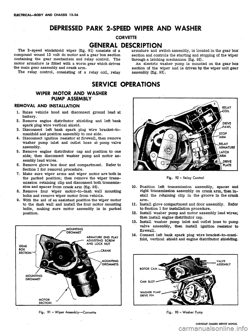
The 2-speed windshield wiper
(fig. 91)
consists
of a
compound wound
12
volt dc motor and
a
gear box section
containing
the
gear mechanism
and
relay control.
The
motor armature
is
fitted with
a
worm gear which drives
the main gear assembly and crank arm.
The relay control, consisting
of a
relay coil, relay
armature
and
switch assembly,
is
located in the gear
box"
section and controls the starting and stopping of the wiper
through
a
latching mechanism (fig. 92).
An electric .washer pump
is
mounted
on the
gear box
section
of the
wiper
and is
driven by the wiper unit gear
assembly (fig. 93).
SERVICE OPERATIONS
WIPER MOTOR
AND
WASHER
PUMP ASSEMBLY
REMOVAL AND INSTALLATION
1.
Raise vehicle hood
and
disconnect, ground lead
at
battery.
2.
Remove engine distributor shielding
and
left bank
spark plug wire vertical shield.
3.
Disconnect left bank spark plug wire bracket-to-
manifold and position assembly to one side.
4.
Disconnect ignition resistor at firewall, then remove
washer pump inlet
and
outlet hose
at
pump valve
assembly.
5.
Remove engine distributor
cap
and position
to one
side;
then disconnect washer pump
and
motor
as-
sembly lead wires.
6. Remove glove
box
door
and
compartment. Refer
to
Section
1
for
removal procedure.
7.
Make sure wiper arms
and
wiper motor are both
in
the parked position; then remove
the
wiper trans-
mission retaining clip and disconnect both transmis-
sion and spacer from crank arm (fig. 93).
8. Remove four wiper motor-to-dash wall mounting
bolts and remove wiper motor from vehicle.
9. With
the aid of
an assistant position the wiper motor
to
the
dash wall
and
install the four motor mounting
bolts,
making sure motor assembly
is in
parked
position.
GEAR
BOX
SECTION
—<
MOUNTING
^*^
GROMMET
MOTOR
_/
SECTION
MOUNTING
/"""GROMMET
ARMATURE
END
PLAY
ADJUSTING SCREW
AND LOCK
NUT
P
^
CRANK
^_ /GROMMETS
RELAY
Fig.
92 -
Relay Control
10.
Position left transmission assembly, spacer
and
right transmission assembly
on
crank arm, then in-
stall
the
retaining clip
in the
groove
in
the crank
arm.
11.
Install glove compartment and door assembly. Refer
to Section
1
for
installation procedure.
12.
Install washer pump and motor assembly lead wires;
then install engine-distributor cap.
13.
Install washer pump inlet
and
outlet hose
to
pump
valve assembly, then install ignition resistor
to
firewall.
14.
Connect left bank spark plug wire bracket-to-mani-
fold, vertical shield and engine distributor shielding.
ROTOR
CAM. ^
CAM SLOT-~-*"'-*
WASHER PUMP^.
DRIVE
PIN
m
M
VALVE
— ASSEMBLY
i
Fig.
91 - Wiper Assembly—Corvette
Fig.
93 - Washer Pump
CHEVROLET CHASSIS SERVICE MANUAL
Page 569 of 659
ELECTRICAL-BODY AND CHASSIS 12-57
15.
Connect positive lead to battery terminal, lower hood
and test wiper and washer assembly for proper
operation.
WIPER TRANSMISSION
REMOVAL AND INSTALLATION
1.
Remove wiper block and arm assembly from trans-
mission.
2.
Remove glove box door and compartment assembly.
Refer to Section 1 for removal procedures.
3.
Remove three transmission-td-cowl retaining
screws.
4.
Remove wiper transmission retaining clip and re-
move transmission from crank arm. Then remove
transmission through the glove box opening.
5.
Reverse removal procedure to install wiper trans-
mission.
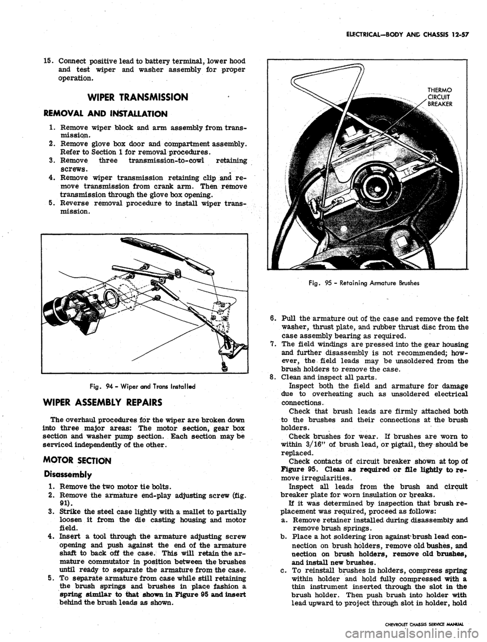
Fig.
94 - Wiper and Trans Installed
WIPER ASSEMBLY REPAIRS
The overhaul procedures for the wiper are broken down
into three major areas: The motor section, gear box
section and washer pump section. Each section may be
serviced independently of the other.
MOTOR SECTION
Disassembly
1.
Remove the two motor tie bolts.
2.
Remove the armature end-play adjusting screw (fig.
91).
3.
Strike the steel case lightly with a mallet to partiaUy
loosen it from the die casting housing and motor
field.
4.
Insert a tool through the armature adjusting screw
opening and push against the end of the armature
shaft to back off the case. This will retain the ar-
mature commutator in position between the brushes
until ready to separate the armature from the case.
5.
To separate armature from case while still retaining
the brush springs and brushes in place fashion a
spring similar to that shown in Figure 95 and insert
behind the brush leads as shown.
Fig.
95 - Retaining Armature Brushes
6. Pull the armature out of the case and remove the felt
washer, thrust plate, and rubber thrust disc from the
case assembly bearing as required.
7.
The field windings are pressed into the gear housing
and further disassembly is not recommended; how-
ever, the field leads may be unsoldered from the
brush holders to remove the case.
8. Clean and inspect all parts.
Inspect both the field and armature for damage
due to overheating such as unsoldered electrical
connections.
Check that brush leads are firmly attached both
to the brushes and their connections at the brush
holders.
Check brushes for wear. If brushes are worn to
within 3/16" of brush lead, or pigtail, they should be
replaced.
Check contacts of circuit breaker shown at top of
Figure 95. Clean as required or file lightly to re-
move irregularities.
Inspect all leads from the brush and circuit
breaker plate for worn insulation or tjreaks.
If it was determined by inspection that brush re-
placement was required, proceed as follows:
a. Remove retainer installed during disassembly and
remove brush springs.
b.
Place a hot soldering iron against*brush lead con-
nection on brush holders, remove old bushes, and
nection on brush holders, remove old brushes,
and install new brushes.
c. To reinstall brushes in holders, compress spring
within holder and hold fully compressed with a
thin instrument inserted through the slot in the
brush holder. Then push brush into holder with
lead upward to project through slot in holder, hold
CHEVROLET CHASSIS SERVICE MANUAL
Page 570 of 659
ELECTRICAL-BODY AND CHASSIS 12-58
RETAINER NUT
.SEAL CAP
THROUGH
BOLT,
CASE
CRANK
ARM
THRUST
BALL
FELT
WASHER
STEEL THRUST PLATE
RUBBER THRUST PLATE
SPACER WASHER
HOUSING
ARMATURE END PLAY
ADJUSTING SCREW
PAWL SPRING'
DRIVE
PAWL'
DRIVE PLATE
WASHER
ASSEMBLY
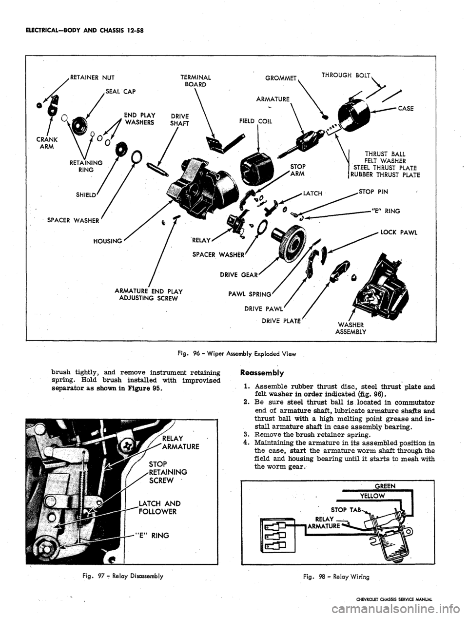
Fig.
96 - Wiper Assembly Exploded View
brush tightly, and remove instrument retaining
spring. Hold brush installed with improvised
separator as shown in Figure 95.
STOP
RETAINING
SCREW
LATCH AND
FOLLOWER
Reassembly
1.
Assemble rubber thrust disc, steel thrust plate and
felt washer in order indicated (fig. 96).
2.
Be sure steel thrust ball is located in commutator
end of armature shaft, lubricate armature shafts and
thrust ball with a high melting point grease and in-
stall armature shaft in case assembly bearing.
3.
Remove the brush retainer spring.
4.
Maintaining the armature in its assembled position in
the case, start the armature worm shaft through the
field and housing bearing until it starts to mesh with
the worm gear.
GREEN
YELLOW
STOP
TAB
RELAY
ARMATURE
Fig.
97 - Relay Disassembly
Fig. 98 - Relay Wiring
CHEVROLET CHASSIS SERVICE MANUAL
Page 572 of 659
ELECTRICAL-BODY AND CHASSIS 12-60
....
£
VALVE ASSEMBLY
mm
BROWN
*yr
RED '
WATER
INTAKE
PORT
|f|i
Wjjm WATER
|HP DISCHARGE
W PORTS
WASHER
PUMP
ASSEMBLY
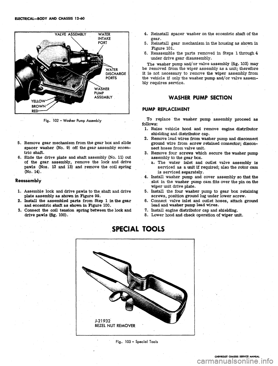
Fig.
102 - Washer Pump Assembly
5. Remove gear mechanism from the gear box and slide
spacer washer (No. 9) off the gear assembly eccen-
tric shaft.
6. Slide the drive plate and shaft assembly (No.. 11) out
of the gear, assembly, remove the lock and drive
pawls (Nos. 12 and 13) and remove the coil spring
(No.
14).
Reassembly
1.
Assemble lock and drive pawls to the shaft and drive
plate assembly as shown in Figure 99.
2.
Install the assembled parts from Step 1 in the gear
and eccentric shaft as shown in Figure 100.
3.
Connect the coil tension spring between the lock and
drive pawls (fig. 100).
4.
Reinstall spacer washer on the eccentric shaft of the
gear.
5. Reinstall gear mechanism in the housing as shown in
Figure 101.
6. Reassemble the parts removed in Steps 1 through 4
under drive gear disassembly.
The washer pump and/or valve assembly (fig. 102) may
be removed from the wiper assembly as a unit; therefore
it is- not necessary to remove the. wiper assembly from
the vehicle if only the washer pump and/or valve assem-
bly requires service.
WASHER PUMP SECTION
PUMP REPLACEMENT
. To replace the washer pump assembly proceed as
follows:
1.
Raise vehicle hood and remove engine distributor
shielding and distributor cap.
2.
Remove lead wires from washer pump and disconnect
ground wire from screw retained connector; discon-
nect hoses from valve unit.
3.
Remove four screws which secure the washer pump
assembly to the gear box.
a* The water inlet and outlet valve assembly is
serviced as a unit if required; also the rotor cam
is serviced separately.
4.
Install washer pump and cover assembly so that the
slot in the washer pump cam fits over the pin on the
wiper unit drive plate.
5. Install the four washer pump to gear box retaining
screws, position ground lug under lower screw.
6. Connect valve inlet and outlet hoses, attach ground
lead and washer pump lead wires.
7. Install engine distributor cap and shielding.
8. Lower hood and check operation of wiper unit.
SPECIAL TOOLS
J-21932
BEZEL NUT REMOVER
Fig.
103 - Special Tools
CHEVROLET CHASSIS SERVICE MANUAL
Page 573 of 659
ELECTRICAL-BODY
AND
CHASSIS
12-61
R.H. FENDER
LAMP (1.6600)
R.H. PARK &
DIR.
S1G. LAMP.
L.H. PARK &
DIR.
SIG. LAMP
L.H. FENDER
LAMP (16600)
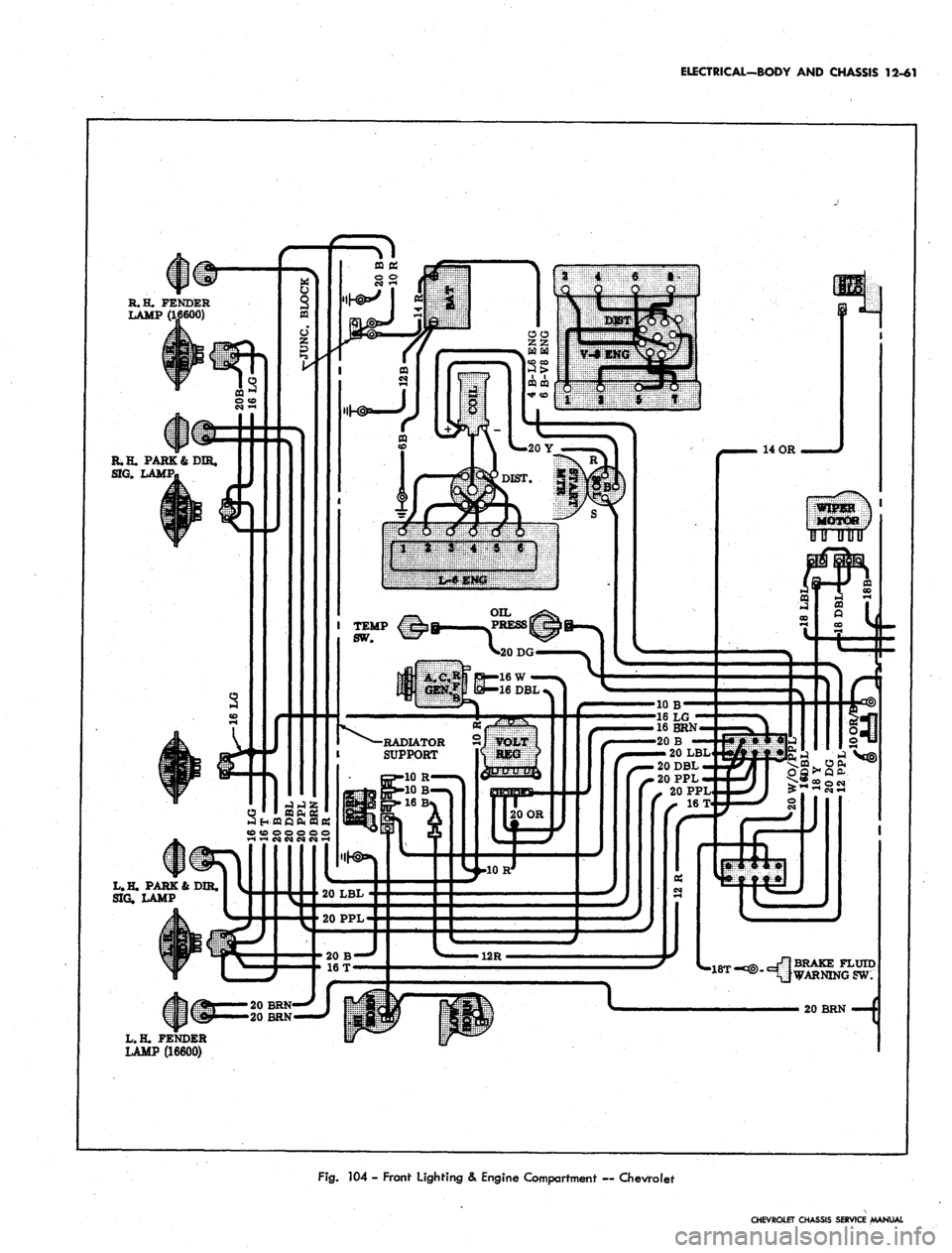
Fig.
104 - Front Lighting & Engine Compartment — Chevrolet
CHEVROLET CHASSIS SERVICE MANUAL
Page 574 of 659
ELECTRICAL-BODY
AND
CHASSIS
12-62
BULKHEAD-
CONNECTOR
HEATER
RESISTOR
PANEL ASM.
12 BRN
20
Y
12 BRN
»-67 MOD ONLY
*45 MOD ONLY
14 PPL
DIRSIG.
FLASHER
20 BRN
'20 LBL
20
P
16 BRN
>20
LG
• 20 PPL
•
14 LBL
• 20
T
.20 OR
-20 DG
20
Y
20
LG
—
20DBL/W.
20
DG
—16 BRN
20 DG
10
OR
TAPE BACK
'10 OR
10 OR/B
18
P
20 BRN
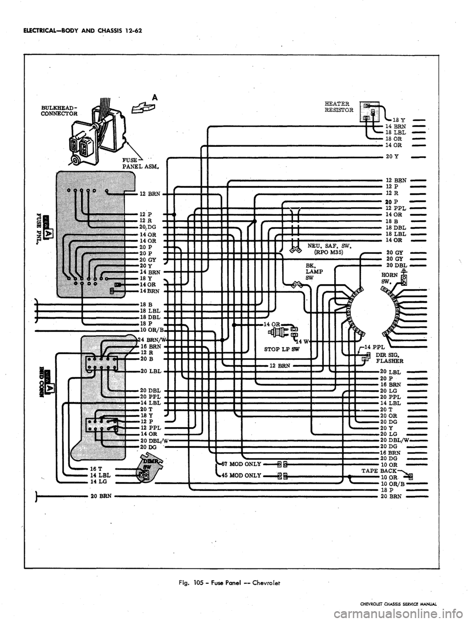
Fig.
105 -
Fuse Panel
—
Chevrolet
CHEVROLET CHASSIS SERVICE MANUAL
Page 575 of 659
ELECTRICAL-BODY AND CHASSIS 12-63
R.H. COURTESY
LP,
(67 MODELS &
16600 ONLY)
•18Y
R. H. DOOR JAMB
SW
(ALL EXCEPT 15300-400)
BK.
NEU.
LP.SW.SAF.SW.
(RJ»JD^
20 OR
20 OR
COMPT
(U*INST. PANEL COMP. LAMP
R-i3r
(ALL EXCEPT 15300-400)
14BRN
18
LBL
18 OR
14 OR
HEATER
CONTROL
LP.
RADIO CONN.
CIG.
LGT
20
P —
4
PPL
20
LG'
14 PPL—
NSOLE
CONN.
(16700-800
ONLY)
CONSOLE
CONN.
(16700-800
ONLY)
12
PPL
14 OR
12 PPL/W
20
GY/B
20 OR
14 OR
20 OR
14 OR
20 OR
20DBL
20 OR
20
GY
INSTRUMENT
CLUSTER
-ILLUM
-ILLUM
-R.H.
S
-GEN
-OILP
-ILLUM
-ILLUM
20 GY
20 GY
20DBI
20DBL/W
18
W
16BRN
-CLOCK-—:(i??T0°)
-ILLUM
^™LY
18
B
18
DBL
18
LBL
-HIGH BEAM—(11
-ILLUM
-
FUEL-GAGE —{30
-ILLUM
-ILLUM-^
-PARK BRAKE
ALARM & BRAKE
WARN. LIGHT
-ENG TEMP.—(35),
(39
-L.H.
SIG.
LAMP—(14
-ILLUM
-
TRAFFIC
HAZARD
SW.
20
LBL
20
P
16BRN
20
LG
20
PPL
14
LBL
20
T
20 OR
20 DG
20 OR
20
t
20 DG
20
Y
20
LG
20
BRN
12
PPL
PARK BRAKE
SW.
20 DBL/W
20 DG
12R
20 DG
10 OR
12
GY
20 OR
18
W
18
W
14
LBL
14T/W
14
B
SW.
67
MOD ONLY
L.H. COURT
LP.
(67 MODELS
&
16600 ONLY)
18 W-'
T/G WINDOW
SW.
(45 MOD ONLY)
DOOR JAMB
SW.
(ALL EXCEPT 15300-400)
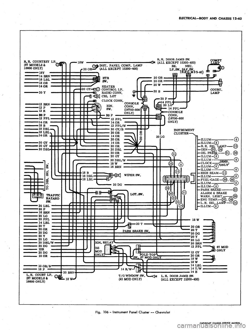
Fig.
106 - Instrument Panel Cluster ~ Chevrolet
CHEVROLET CHASSIS SERVICE MANUAL