phone CHEVROLET DYNASTY 1993 Service Manual
[x] Cancel search | Manufacturer: CHEVROLET, Model Year: 1993, Model line: DYNASTY, Model: CHEVROLET DYNASTY 1993Pages: 2438, PDF Size: 74.98 MB
Page 787 of 2438
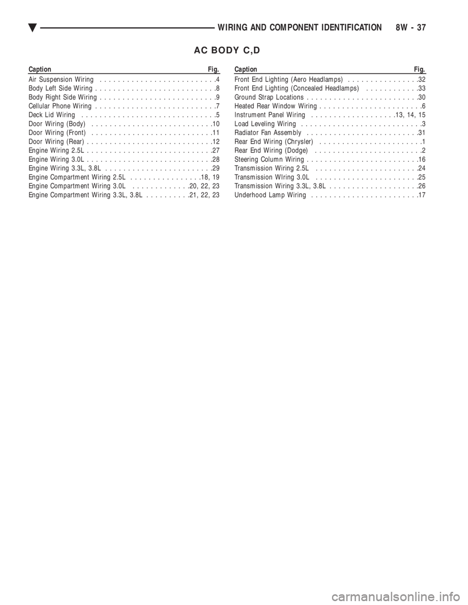
AC BODY C,D
Caption Fig.
Air Suspension Wiring ..........................4
Body Left Side Wiring ...........................8
Body Right Side Wiring ..........................9
Cellular Phone Wiring ...........................7
Deck Lid Wiring ..............................5
Door Wiring (Body) ...........................10
Door Wiring (Front) ...........................11
Door Wiring (Rear) ............................12
Engine Wiring 2.5L ............................27
Engine Wiring 3.0L ............................28
Engine Wiring 3.3L, 3.8L ........................29
Engine Compartment Wiring 2.5L ................18, 19
Engine Compartment Wiring 3.0L .............20, 22, 23
Engine Compartment Wiring 3.3L, 3.8L ..........21, 22, 23Caption Fig.
Front End Lighting (Aero Headlamps) ................32
Front End Lighting (Concealed Headlamps) ............33
Ground Strap Locations .........................30
Heated Rear Window Wiring .......................6
Instrument Panel Wiring .................. .13, 14, 15
Load Leveling Wiring ...........................3
Radiator Fan Assembly .........................31
Rear End Wiring (Chrysler) .......................1
Rear End Wiring (Dodge) ........................2
Steering Column Wiring .........................16
Transmission Wiring 2.5L .......................24
Transmission WIring 3.0L .......................25
Transmission Wiring 3.3L, 3.8L ....................26
Underhood Lamp Wiring ........................17
Ä WIRING AND COMPONENT IDENTIFICATION 8W - 37
Page 791 of 2438
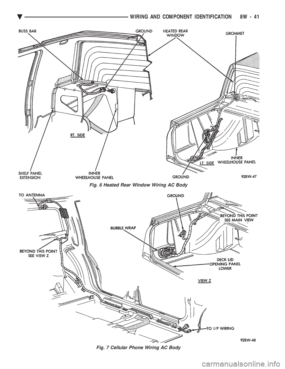
Fig. 6 Heated Rear Window Wiring AC Body
Fig. 7 Cellular Phone Wiring AC Body
Ä WIRING AND COMPONENT IDENTIFICATION 8W - 41
Page 861 of 2438
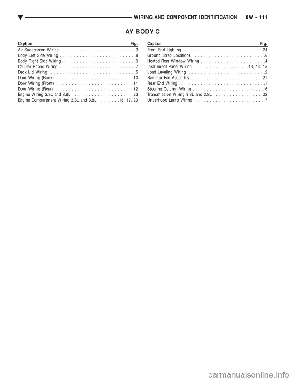
AY BODY-C
Caption Fig.
Air Suspension Wiring ..........................3
Body Left Side Wiring ...........................8
Body Right Side Wiring ..........................9
Cellular Phone Wiring ...........................7
Deck Lid Wiring ..............................5
Door Wiring (Body) ...........................10
Door Wiring (Front) ...........................11
Door Wiring (Rear) ............................12
Engine Wiring 3.3L and 3.8L .....................23
Engine Compartment Wiring 3.3L and 3.8L .......18, 19, 20Caption Fig.
Front End Lighting ............................24
Ground Strap Locations .........................6
Heated Rear Window Wiring .......................4
Instrument Panel Wiring .................. .13, 14, 15
Load Leveling Wiring ...........................2
Radiator Fan Assembly .........................21
Rear End Wiring ..............................1
Steering Column Wiring .........................16
Transmission Wiring 3.3L and 3.8L .................22
Underhood Lamp Wiring ........................17
Ä WIRING AND COMPONENT IDENTIFICATION 8W - 111
Page 865 of 2438
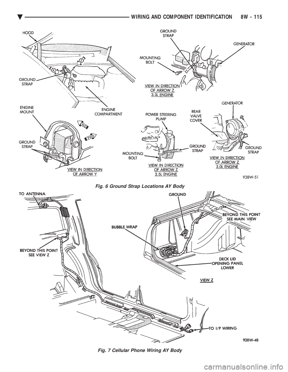
Fig. 6 Ground Strap Locations AY Body
Fig. 7 Cellular Phone Wiring AY Body
Ä WIRING AND COMPONENT IDENTIFICATION 8W - 115
Page 1064 of 2438
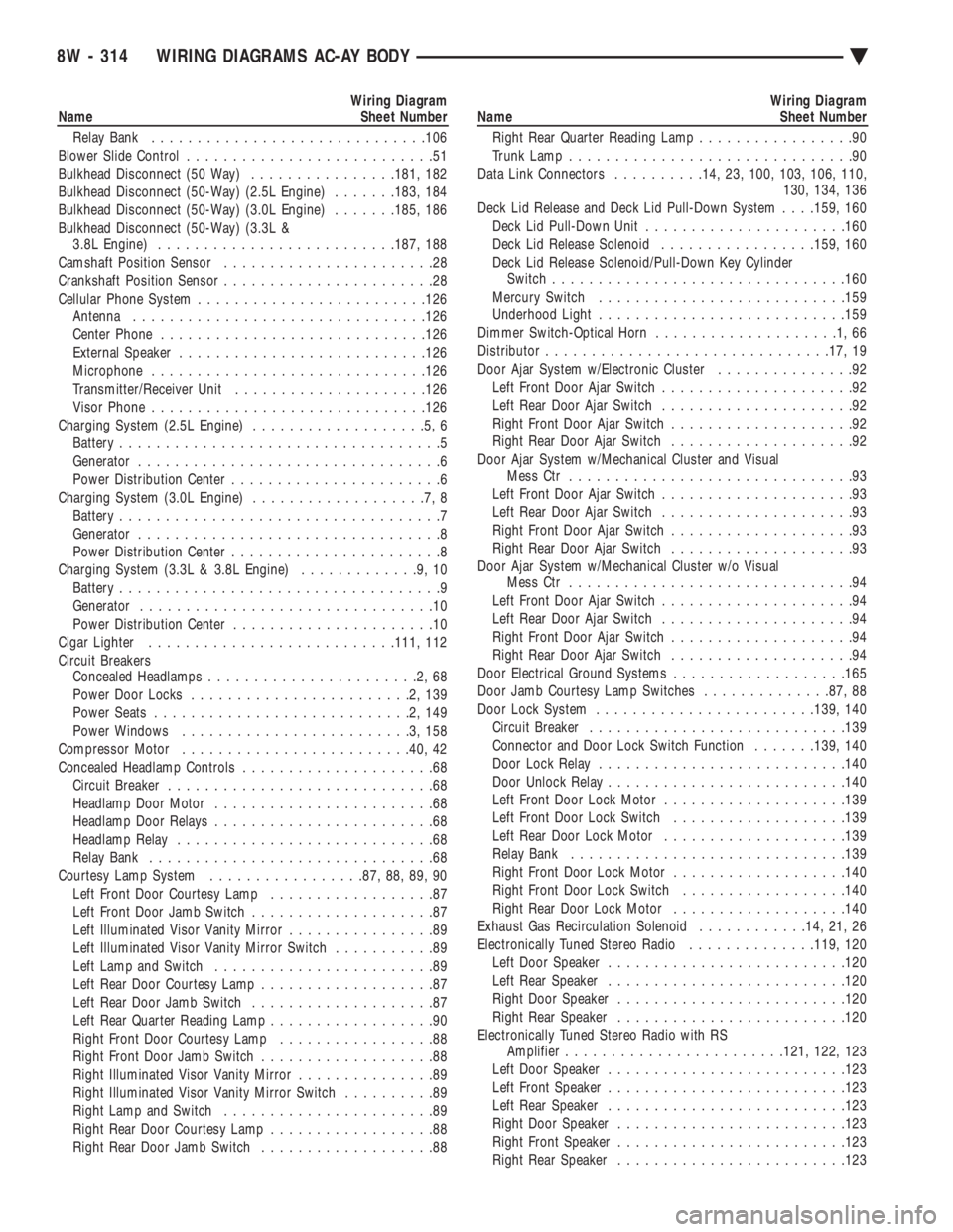
Wiring Diagram
Name Sheet Number
Relay Bank ............................. .106
Blower Slide Control ...........................51
Bulkhead Disconnect (50 Way) ................181, 182
Bulkhead Disconnect (50-Way) (2.5L Engine) .......183, 184
Bulkhead Disconnect (50-Way) (3.0L Engine) .......185, 186
Bulkhead Disconnect (50-Way) (3.3L & 3.8L Engine) ......................... .187, 188
Camshaft Position Sensor .......................28
Crankshaft Position Sensor .......................28
Cellular Phone System ........................ .126
Antenna ............................... .126
Center Phone ............................ .126
External Speaker .......................... .126
Microphone ............................. .126
Transmitter/Receiver Unit .................... .126
Visor Phone ............................. .126
Charging System (2.5L Engine) ...................5,6
Battery ...................................5
Generator .................................6
Power Distribution Center .......................6
Charging System (3.0L Engine) ...................7,8
Battery ...................................7
Generator .................................8
Power Distribution Center .......................8
Charging System (3.3L & 3.8L Engine) .............9,10
Battery ...................................9
Generator ................................10
Power Distribution Center ......................10
Cigar Lighter .......................... .111, 112
Circuit Breakers Concealed Headlamps .......................2,68
Power Door Locks ........................2,139
Power Seats ............................2,149
Power Windows .........................3,158
Compressor Motor ........................ .40, 42
Concealed Headlamp Controls .....................68
Circuit Breaker .............................68
Headlamp Door Motor ........................68
Headlamp Door Relays ........................68
Headlamp Relay ............................68
Relay Bank ...............................68
Courtesy Lamp System .................87, 88, 89, 90
Left Front Door Courtesy Lamp ..................87
Left Front Door Jamb Switch ....................87
Left Illuminated Visor Vanity Mirror ................89
Left Illuminated Visor Vanity Mirror Switch ...........89
Left Lamp and Switch ........................89
Left Rear Door Courtesy Lamp ...................87
Left Rear Door Jamb Switch ....................87
Left Rear Quarter Reading Lamp ..................90
Right Front Door Courtesy Lamp .................88
Right Front Door Jamb Switch ...................88
Right Illuminated Visor Vanity Mirror ...............89
Right Illuminated Visor Vanity Mirror Switch ..........89
Right Lamp and Switch .......................89
Right Rear Door Courtesy Lamp ..................88
Right Rear Door Jamb Switch ...................88Wiring Diagram
Name Sheet Number
Right Rear Quarter Reading Lamp .................90
Trunk Lamp ...............................90
Data Link Connectors ..........14, 23, 100, 103, 106, 110,
130, 134, 136
Deck Lid Release and Deck Lid Pull-Down System . . . .159, 160
Deck Lid Pull-Down Unit ..................... .160
Deck Lid Release Solenoid .................159, 160
Deck Lid Release Solenoid/Pull-Down Key Cylinder Switch ............................... .160
Mercury Switch .......................... .159
Underhood Light .......................... .159
Dimmer Switch-Optical Horn ....................1,66
Distributor .............................. .17, 19
Door Ajar System w/Electronic Cluster ...............92
Left Front Door Ajar Switch .....................92
Left Rear Door Ajar Switch .....................92
Right Front Door Ajar Switch ....................92
Right Rear Door Ajar Switch ....................92
Door Ajar System w/Mechanical Cluster and Visual Mess Ctr ...............................93
Left Front Door Ajar Switch .....................93
Left Rear Door Ajar Switch .....................93
Right Front Door Ajar Switch ....................93
Right Rear Door Ajar Switch ....................93
Door Ajar System w/Mechanical Cluster w/o Visual Mess Ctr ...............................94
Left Front Door Ajar Switch .....................94
Left Rear Door Ajar Switch .....................94
Right Front Door Ajar Switch ....................94
Right Rear Door Ajar Switch ....................94
Door Electrical Ground Systems ...................165
Door Jamb Courtesy Lamp Switches ..............87, 88
Door Lock System ....................... .139, 140
Circuit Breaker ........................... .139
Connector and Door Lock Switch Function .......139, 140
Door Lock Relay .......................... .140
Door Unlock Relay ......................... .140
Left Front Door Lock Motor ................... .139
Left Front Door Lock Switch ...................139
Left Rear Door Lock Motor ................... .139
Relay Bank ............................. .139
Right Front Door Lock Motor ...................140
Right Front Door Lock Switch ..................140
Right Rear Door Lock Motor ...................140
Exhaust Gas Recirculation Solenoid ............14, 21, 26
Electronically Tuned Stereo Radio ..............119, 120
Left Door Speaker ......................... .120
Left Rear Speaker ......................... .120
Right Door Speaker ........................ .120
Right Rear Speaker ........................ .120
Electronically Tuned Stereo Radio with RS Amplifier ....................... .121, 122, 123
Left Door Speaker ......................... .123
Left Front Speaker ......................... .123
Left Rear Speaker ......................... .123
Right Door Speaker ........................ .123
Right Front Speaker ........................ .123
Right Rear Speaker ........................ .123
8W - 314 WIRING DIAGRAMS AC-AY BODY Ä
Page 1072 of 2438
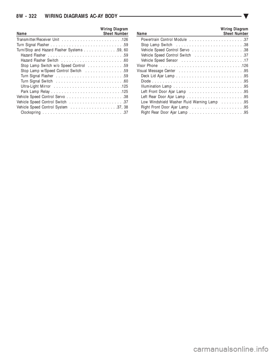
Wiring Diagram
Name Sheet Number
Transmitter/Receiver Unit ...................... .126
Turn Signal Flasher ............................59
Turn/Stop and Hazard Flasher Systems .............59, 60
Hazard Flasher .............................59
Hazard Flasher Switch ........................60
Stop Lamp Switch w/o Speed Control ..............59
Stop Lamp w/Speed Control Switch ...............59
Turn Signal Flasher ..........................59
Turn Signal Switch ..........................60
Ultra-Light Mirror ......................... .125
Park Lamp Relay .......................... .125
Vehicle Speed Control Servo ......................38
Vehicle Speed Control Switch .....................37
Vehicle Speed Control System ..................37, 38
Clockspring ...............................37Wiring Diagram
Name Sheet Number
Powertrain Control Module .....................37
Stop Lamp Switch ..........................38
Vehicle Speed Control Servo ....................38
Vehicle Speed Control Switch ...................37
Vehicle Speed Sensor ........................17
Visor Phone .............................. .126
Visual Message Center .........................95
Deck Lid Ajar Lamp ..........................95
Diode ...................................95
Illumination Lamp ...........................95
Left Front Door Ajar Lamp .....................95
Left Rear Door Ajar Lamp ......................95
Low Windshield Washer Fluid Warning Lamp .........95
Right Front Door Ajar Lamp ....................95
Right Rear Door Ajar Lamp .....................95
8W - 322 WIRING DIAGRAMS AC-AY BODY Ä
Page 2426 of 2438
UNITED STATES
The special service tools referred to herein are required for certain service operations. These special service tools
or their equivalent, if not obtainable through a local source, are available through the following outlet.
28635 Mound Road, Warren, Michigan 48092, U.S.A.
MILLER SPECIAL TOOLS
OTC Division, SPX Corporation
Telephone 1-800-801-5420 FAX 1-800-578-7375
CANADA
The special service tools referred to herein are required for certain service operations. These special service tools
or their equivalent, if not obtainable through a local source, are available through the following outlet.
C & D Riley Enterprises Ltd., P.O. Box 243, Amherstburg, Ontario N9V 2Z4
Telephone (519) 736-4600 FAX (519) 736-8433
INTERNATIONAL
The special service tools referred to herein are required for certain service operations. These special service tools
or their equivalent, if not obtainable through a local source, are available through the following outlet.
28635 Mound Road, Warren, Michigan 48092, U.S.A.
MILLER SPECIAL TOOLS
OTC Division, SPX Corporation
Telephone 1-800-801-5420 FAX 1-800-578-7375
NEXT PAGE ©
Page 2427 of 2438
CAUTION
ALL SERVICE AND REBUILDING INSTRUCTIONS CONTAINED HEREIN
ARE APPLICABLE TO, AND FOR THE CONVENIENCE OF, THE AUTOMOTIVE
TRADE ONLY. All test and repair procedures on components or assemblies in
non-automotive applications should be repaired in accordance with instructions
supplied by the manufacturer of the total product.
Proper service and repair is important to the safe, reliable, operation of all motor
vehicles. The service procedures recommended and described in this publication were
developed for professional service personnel and are effective methods for performing
vehicle repair. Following these procedures will help assure efficient economical vehicle
performance and service reliability. Some of these service procedures require the use
of special tools designed for specific procedures. These special tools should be used
when recommended throughout this publication.
Special attention should be exercised when working with spring or tension loaded
fasteners and devices such as E-Clips, Circlips, Snap rings, etc., as careless removal
may cause personal injury. Always wear safety goggles whenever working on vehicles
or vehicle components.
It is important to note that this publication contains various CautionsandWarnings.
These should be carefully read in order to minimize the risk of personal injury, or the
possibility that improper service methods may damage the vehicle or render it unsafe.
It is important to note that these CautionsandWarnings cover only the situations
and procedures DaimlerChrysler Corporation has encountered and recommended.
DaimlerChrysler Corporation could not possibly know, evaluate, and advise the
service trade of all conceivable ways that service may be performed, or of the possible
hazards of each. Consequently, DaimlerChrysler Corporation has not undertaken any
such broad service review. Accordingly, anyone who uses a service procedure, or tool,
that is not recommended in this publication must assure oneself thoroughly that
neither personal safety, nor vehicle safety, be jeopardized by the service methods they
select.
SERVICE AND OWNER MANUALS
Available for Chrysler, Plymouth, Dodge, Dodge Truck, and Jeep
Tvehicles.
Telephone orders may be placed at the number below.
Credit cards are accepted (no CODs). Please have your
order information available at time of call.
CALL: (800) 890-4038 OR FAX: (440) 572-0815
FOR A FREE CATALOG OR TO PLACE AN ORDER.
NEXT PAGE ©
llllllllllll