turn signal bulb CHRYSLER CARAVAN 2003 Service Manual
[x] Cancel search | Manufacturer: CHRYSLER, Model Year: 2003, Model line: CARAVAN, Model: CHRYSLER CARAVAN 2003Pages: 2177, PDF Size: 59.81 MB
Page 330 of 2177
OPERATION - SENSOR RETURN - PCM INPUT
The sensor return circuit provides a low electrical
noise ground reference for all of the systems sensors.
The sensor return circuit connects to internal ground
circuits within the Powertrain Control Module
(PCM).
OPERATION - DATA BUS COMMUNICATION
RECEIVE - PCM INPUT
The PCM uses the SCI communication bus to pre-
form engine diagnostics and flash operations. The
transmission side of the PCM uses the SCI commu-
nication bus to flash new software. However, diagnos-
tics is performed via the vehicles J1850 bus for the
transmission side of the PCM.
OPERATION - IGNITION SENSE - PCM INPUT
The ignition sense input informs the Powertrain
Control Module (PCM) that the ignition switch is in
the crank or run position.
OPERATION - PCM GROUND
Ground is provided through multiple pins of the
PCM connector. Depending on the vehicle there may
be as many as two different ground pins. There are
power grounds and sensor grounds.
The power grounds are used to control the ground
side relays, solenoids, ignition coil or injectors. The
signal ground is used for any input that uses sensor
return for ground, and the ground side of any inter-
nal processing component.
The PCM case is shielded to prevent RFI and EMI.
The PCM case is grounded and must be firmly
attached to a good, clean body ground.
Internally all grounds are connected together, how-
ever there is noise suppression on the sensor ground.
For EMI and RFI protection the housing and cover
are also grounded separately from the ground pins.
OPERATION
OPERATION - 8-VOLT SUPPLY - PCM OUTPUT
- SBEC CONTROLLER
The PCM supplies 8 volts to the crankshaft posi-
tion sensor, camshaft position sensor.
OPERATION - 5 VOLT SUPPLY - PCM OUTPUT
The PCM supplies 5 volts to the following sensors:
²A/C pressure transducer
²Ambient Temperature sensor
²Battery temperature
²Camshaft Position Sensor (NGC)
²Crankshaft Position Sensor (NGC)
²Electronic Throttle Control (1.6L)²Engine coolant temperature sensor
²Inlet Air Temperature Sensor
²Knock sensor
²Linear EGR solenoid (if equipped)
²Manifold absolute pressure sensor
²Oil Pressure Switch
²Pedal Position Sensor (1.6L)
²Throttle position sensor
²Vehicle Speed Sensor
STANDARD PROCEDURE
STANDARD PROCEDURE - OBTAINING
DIAGNOSTIC TROUBLE CODES
BULB CHECK
Key on: Bulb illuminated until vehicle starts, as
long as all once per trip (readiness) monitors com-
pleted. If monitors havenotbeen completed, then:
Key on: bulb check for about 5 to 8 seconds, lamp
then flashes if once per trip (readiness) monitors
havenotbeen completed until vehicle is started,
then MIL is extinguished.
OBTAINING DTC'S USING DRB SCAN TOOL
(1) Connect the DRB scan tool to the data link
(diagnostic) connector. This connector is located in
the passenger compartment; at the lower edge of
instrument panel; near the steering column.
(2) Turn the ignition switch on and access the
ªRead Faultº screen.
(3) Record all the DTC's and ªfreeze frameº infor-
mation shown on the DRB scan tool.
(4) To erase DTC's, use the ªErase Trouble Codeº
data screen on the DRB scan tool.Do not erase any
DTC's until problems have been investigated
and repairs have been performed.
STANDARD PROCEDURE - PINION FACTOR
SETTING
NOTE: This procedure must be performed if the
PCM/TCM has been replaced with a NEW or
replacement unit. Failure to perform this procedure
will result in an inoperative or improperly calibrated
speedometer.
The vehicle speed readings for the speedometer are
taken from the output speed sensor. The PCM/TCM
must be calibrated to the different combinations of
equipment (final drive and tires) available. Pinion
Factor allows the technician to set the Powertrain/
Transmission Control Module initial setting so that
the speedometer readings will be correct. To properly
RSELECTRONIC CONTROL MODULES8E-15
POWERTRAIN CONTROL MODULE (Continued)
ProCarManuals.com
Page 406 of 2177
INSTRUMENT CLUSTER
TABLE OF CONTENTS
page page
INSTRUMENT CLUSTER
DESCRIPTION..........................1
OPERATION............................1
DIAGNOSIS AND TESTING
DIAGNOSIS AND TESTING - SELF-
DIAGNOSTICS.........................2
DIAGNOSIS AND TESTING - CLUSTER
DIAGNOSIS...........................2REMOVAL.............................10
INSTALLATION.........................10
CLUSTER LENS
REMOVAL.............................10
INSTALLATION.........................10
INSTRUMENT CLUSTER
DESCRIPTION
The instrumentation gauges are contained in a
subdial assembly within the instrument cluster. The
individual gauges are not serviceable. If one of the
cluster gauges becomes faulty, the entire cluster
would require replacement.
The Mechanical Instrument Cluster (MIC) with a
tachometer is equipped with a electronic vacuum flu-
orescent transmission range indicator (PRND3L),
odometer, and trip odometer display.
The MIC without a tachometer is equipped with a
Light Emitting Diode (LED) transmission range indi-
cator (PRND3L) and a vacuum fluorescent odometer
display.
The MIC is equipped with the following warning
lamps.
²Lift Gate Ajar
²Low Fuel Level
²Low Windshield Washer Fluid Level
²Cruise
²Battery Voltage
²Fasten Seat Belt
²Door Ajar
²Coolant Temperature
²Anti-Lock Brake
²Brake
²Oil Pressure
²MIL (Malfunction Indicator Lamp)
²VTSS/SKIS Indicator
²Airbag
²Traction Control
²Autostick
The MIC without a tachometer also has the follow-
ing warning lamps:
²Turns Signals
²High Beam
WATER IN FUEL LAMP - EXPORT
The Water In Fuel Lamp is located in the message
center. When moisture is found within the fuel sys-
tem, the sensor sends a message via the PCI data
bus to the instrument cluster. The MIC illuminates
the bulb in the message center, The sensor is located
underneath the vehicle, directly above the rear axle.
The sensor is housed within the fuel filter/water sep-
arator assembly cover. The sensor is not serviced sep-
arately. If found defective, the entire assembly cover
must be replaced.
OPERATION
Refer to the vehicle Owner's Manual for operation
instructions and conditions for the Instrument Clus-
ter Gauges.
WATER IN FUEL LAMP - EXPORT
The Water In Fuel Sensor is a resistive type
switch. It is calibrated to sense the different resis-
tance between diesel fuel and water. When water
enters the fuel system, it is caught in the bottom of
the fuel filter/water separator assembly, where the
sensor is located. Water has less resistance than die-
sel fuel. The sensor then sends a PCI data bus mes-
sage to the instrument cluster to illuminate the
lamp.
If the lamp is inoperative, perform the self diag-
nostic test on the instrument cluster to check the
lamp operation before continuing diagnosis.
RSINSTRUMENT CLUSTER8J-1
ProCarManuals.com
Page 417 of 2177
MULTI-FUNCTION SWITCH
DESCRIPTION - TURN SIGNAL SYSTEM.....21
OPERATION - TURN SIGNAL SYSTEM.......21
DIAGNOSIS AND TESTING - MULTI-
FUNCTION SWITCH...................21
REMOVAL.............................21
INSTALLATION.........................21
PARK/TURN SIGNAL LAMP
REMOVAL.............................21
INSTALLATION.........................21
PARK/TURN SIGNAL LAMP - EXPORT
REMOVAL.............................22
INSTALLATION.........................22
REAR FOG LAMP - EXPORT
DESCRIPTION.........................22REPEATER LAMP - EXPORT
REMOVAL.............................22
INSTALLATION.........................22
TAIL LAMP
REMOVAL.............................22
INSTALLATION.........................22
TAIL LAMP - EXPORT
REMOVAL.............................23
INSTALLATION.........................23
TAIL LAMP UNIT
REMOVAL.............................23
INSTALLATION.........................23
LAMPS/LIGHTING - EXTERIOR
DESCRIPTION
LAMP SYSTEMS
Lighting circuits are protected by fuses. Lighting
circuits require an overload protected power and high
side drivers source, ON/OFF device, lamps and body
grounds to operate properly. Plastic lamps require a
wire in the harness to supply body ground to the
lamp socket. Replace sockets and bulbs that are cor-
roded.
Some of the interior and exterior lighting functions
are governed by the Body Control Module (BCM).
The headlamp, dome, and the door ajar switches pro-
vide signals to the BCM. The BCM in turn sends a
Programmable Communication Interface (PCI) bus
message to the Front Control Module (FCM) to
enable the necessary drivers to set the required illu-
mination configuration.
Wire connectors can make intermittent contact or
become corroded. Before coupling wire connectors,
inspect the terminals inside the connector. Male ter-
minals should not be bent or disengaged from the
insulator. Female terminals should not be sprung
open or disengaged from the insulator. Bent and
sprung terminals can be repaired using needle nose
pliers and pick tool. Corroded terminals appear
chalky or green. Corroded terminals should be
replaced to avoid recurrence of the problem symp-
toms.
Begin electrical system failure diagnosis by testing
related fuses in the fuse block and intelligent power
module. Verify that bulbs are in good condition and
test continuity of the circuit ground. Refer to the
appropriate wiring information.
AUTOMATIC HEADLAMP SYSTEM
The Automatic Headlamp system turns the instru-
mentation and exterior illumination lamps ON when
the ambient light levels are Night and the engine
RPM is 450 or above, and OFF when light levels are
Day.
DAYTIME RUNNING LAMPS
Operating the high-beam headlamps at reduced
power provides daytime running lamps, which are
required on all new Canadian vehicles.
HEADLAMPS ON WITH WINDSHIELD WIPERS
For vehicles equipped with the Automatic Head-
lamp System, the instrumentation and exterior illu-
mination lamps will be turned ON when the
headlamp switch is in the AUTO position, RPM >
450 and the windshield wipers have been in the
intermittent, low or high mode of operation for more
than ten seconds. When the windshield wipers are
turned OFF the Body Control Module will determine
if the instrumentation and exterior illumination
lamps should remain ON base upon the current
ambient light level.
HEADLAMP SYSTEM
The configuration of the headlamp system of head-
lamps, park lamps and fog lamps is determined by
the BCM. The BCM determines the lighting configu-
ration as a result of the inputs from the ignition
switch, headlamp switch and multi-function switch. A
PCI bus is transmitted from the BCM to the FCM to
enable the necessary drivers to set the illumination
configuration. Four wires are connected between the
headlamp switch and the BCM. The first wire con-
tains information regarding the position of the head-
lamp switch (Off, Automatic Headlamps, Automatic
Headlamp switch fog, Park with Fog, Head, or Head
with Fog Lamps). The second wire contains informa-
tion regarding the position of the dimmer switch
8L - 2 LAMPS/LIGHTING - EXTERIORRS
ProCarManuals.com
Page 419 of 2177
WARNING
WARNING: EYE PROTECTION SHOULD BE USED
WHEN SERVICING GLASS COMPONENTS. PER-
SONAL INJURY CAN RESULT.
CAUTION: Do not touch the glass of halogen bulbs
with fingers or other possibly oily surface, reduced
bulb life will result. Do not use bulbs other than
those indicated in the Bulb Application table. Dam-
age to lamp and/or Daytime Running Lamp Module
can result. Do not use fuses, circuit breakers or
relays having greater amperage value than indi-
cated on the fuse panel or in the Owners Manual.
CAUTION: Do not use bulbs other than those listed
in the Bulb Application Table. Damage to lamp can
result. Do not touch halogen bulbs with fingers or
other oily surfaces. Bulb life will be reduced.
SPECIFICATIONS
EXTERIOR LAMPS
BULB APPLICATION TABLE
LAMP BULB
BACK-UP 3057
CHMSL 921
FRONT SIDE MARKER/PARK/
TURN3157A
FRONT FOG 9040
HEADLAMP 9007
LICENSE 168
TAIL, STOP 3057
TURN SIGNAL 3057
BULB APPLICATION TABLE - EXPORT
LAMP BULB
HEADLAMP LOW/HIGH BEAM H7
FRONT FOG H3
FRONT POSITION W5W
FRONT TURN SIGNAL PY21W
SIDE REPEATER T4W
LICENSE PLATE W5W/168
REAR TAIL AND STOP P21/5W
REAR TURN SIGNAL PY21W
BACK-UP P21W
REAR FOG P21W
CHMSL W16W/921
BRAKE LAMP SWITCH
DESCRIPTION
The brake lamp switch is located under the instru-
ment panel, at the brake pedal arm (Fig. 3). It has
three internal switches controlling various functions
of the vehicle. It's main function is to control opera-
tion of the vehicle's brake lamps. Other functions
include speed control deactivation, brake sense for
the antilock brake system and brake sense for the
brake transmission shift interlock.
CAUTION: The switch can only be adjusted once.
That is during initial installation of the switch. If the
switch is not adjusted properly or has been
removed for some service, a new switch must be
installed and adjusted.
OPERATION
When the brake pedal is pressed, the plunger on
the outside of the brake lamp switch extends out-
ward. This action opens or closes the contacts of the
three switches inside the brake lamp switch.
With the brake pedal pressed down (plunger
extended), the switch for terminals 1 and 2 is closed
completing the circuit. The switch for terminals 3
and 4 is open and so is the switch for terminals 5
and 6.
When the brake pedal is released (plunger pushed
in), the three switches assume the opposite positions.
The switch for terminals 1 and 2 is now open while
the other two switches are now closed, completing
their circuits.
A lever on the back of the switch is used to set the
switch into the ªadjustedº position. A non-adjusted
switch will have the lever set to the diagonal position
in relation to the switch housing. The plunger can be
moved in and out, but the states of the internal
switches will not change.
CAUTION: Never move the adjustment lever of the
new brake lamp switch without it being properly
installed in the vehicle first. Such action will render
the switch unusable and the switch must be dis-
carded.
Once installed in the vehicle as described in the
brake lamp switch installation procedure (Refer to 8 -
ELECTRICAL/LAMPS/LIGHTING - EXTERIOR/
BRAKE LAMP SWITCH - INSTALLATION), the new
switch's adjustment lever is rotated to the adjusted
position as indicated (Fig. 4). This action locks the
plunger to the internal switches.Once in this posi-
tion the switch is permanently adjusted (or
8L - 4 LAMPS/LIGHTING - EXTERIORRS
LAMPS/LIGHTING - EXTERIOR (Continued)
ProCarManuals.com
Page 426 of 2177
HEADLAMP
DIAGNOSIS AND TESTING - HEADLAMP
When a vehicle experiences problems with the
headlamp system, verify the condition of the battery
connections, fuses, charging system, headlamp bulbs,
wire connectors, relay, high beam switch, dimmer
switch, and headlamp switch. Refer to the appropri-
ate wiring information.
Each vehicle is equipped with various lamp assem-
blies. A good ground is necessary for proper lighting
operation. Grounding is provided by the lamp socket
when it comes in contact with the metal body, or
through a separate ground wire.
When changing lamp bulbs check the socket for
corrosion. If corrosion is present, clean it with a wire
brush.
When it is necessary to remove components to ser-
vice another, it should not be necessary to apply
excessive force or bend a component to remove it.
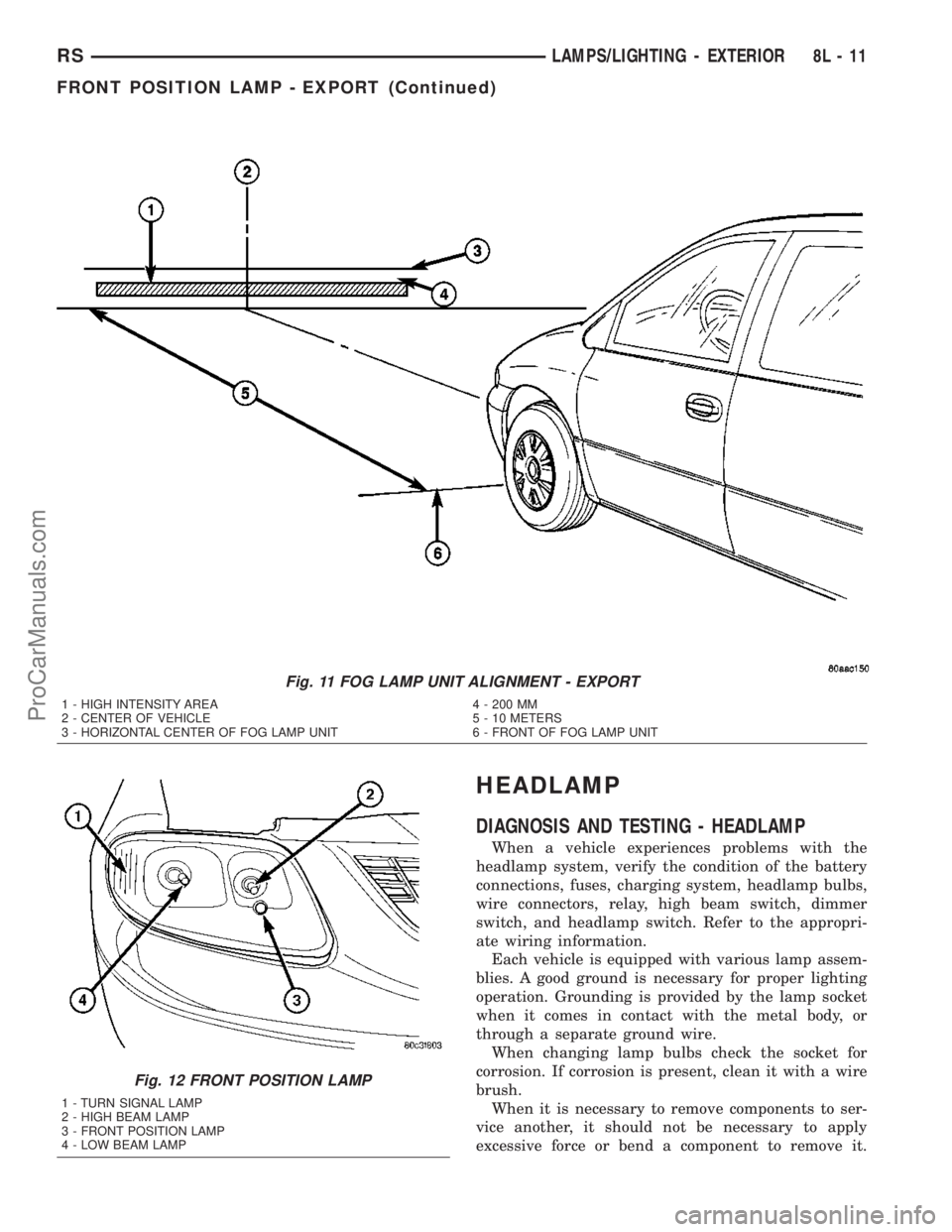
Fig. 11 FOG LAMP UNIT ALIGNMENT - EXPORT
1 - HIGH INTENSITY AREA 4 - 200 MM
2 - CENTER OF VEHICLE 5 - 10 METERS
3 - HORIZONTAL CENTER OF FOG LAMP UNIT 6 - FRONT OF FOG LAMP UNIT
Fig. 12 FRONT POSITION LAMP
1 - TURN SIGNAL LAMP
2 - HIGH BEAM LAMP
3 - FRONT POSITION LAMP
4 - LOW BEAM LAMP
RSLAMPS/LIGHTING - EXTERIOR8L-11
FRONT POSITION LAMP - EXPORT (Continued)
ProCarManuals.com
Page 435 of 2177

(2) Remove the three retaining screws (Fig. 23).
(3) Disconnect the wiring harness from the bulbs
(Fig. 24).
(4) Remove wire harness retainer from back of
headlamp unit.
(5) Remove the headlamp unit.
INSTALLATION
(1) Reconnect wire harness to the bulbs.
(2) Install wire harness retainer to headlamp unit.
(3) Install the three retaining screws.
(4) Reconnect the battery negative cable.
HEADLAMP UNIT - EXPORT
REMOVAL
(1) Disconnect and isolate the battery negative
cable.
(2) Remove the three retaining screws.
(3) Disconnect the central wiring harness connec-
tor from the headlamp unit.
(4) Remove the headlamp unit from vehicle.
INSTALLATION
(1) Connect the wiring harness to the headlamp
unit's central connector.
(2) Place headlamp unit into headlamp unit pocket
in front end.
(3) Install the three retaining screws.
(4) Connect the battery negative cable.
(5) Verify vehicle and system operation.
LICENSE LAMP
REMOVAL
(1) Disconnect and isolate the battery negative
cable.
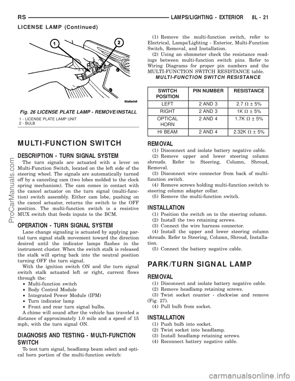
(2) Remove two screws (Fig. 25).
(3) Twist bulb socket and remove (Fig. 26).
(4) Pull bulb from socket.
INSTALLATION
(1) Push bulb into socket.
(2) Install socket into lamp.
(3) Install two screws.
(4) Reconnect the battery negative cable.
Fig. 23 HEADLAMP UNIT FASTENERS
1 - HEADLAMP UNIT RETAINING SCREW
2 - HEADLAMP UNIT
Fig. 24 HEADLAMP UNIT
1 - HEADLAMP UNIT
2 - HEADLAMP
3 - PARK/TURN SIGNAL LAMP
4 - WIRE HARNESS RETAINER
Fig. 25 LICENSE PLATE LAMP UNITS
1 - SCREW
2 - LICENSE PLATE LAMP
8L - 20 LAMPS/LIGHTING - EXTERIORRS
HEADLAMP UNIT (Continued)
ProCarManuals.com
Page 436 of 2177
MULTI-FUNCTION SWITCH
DESCRIPTION - TURN SIGNAL SYSTEM
The turn signals are actuated with a lever on
Multi-Function Switch, located on the left side of the
steering wheel. The signals are automatically turned
off by a canceling cam (two lobes molded to the clock
spring mechanism). The cam comes in contact with
the cancel actuator on the turn signal (multi-func-
tion) switch assembly. Either cam lobe, pushing on
the cancel actuator, returns the switch to the OFF
position. The multi-function switch is a resistive
MUX switch that feeds inputs to the BCM.
OPERATION - TURN SIGNAL SYSTEM
Lane change signaling is actuated by applying par-
tial turn signal stalk movement toward the direction
desired until the indicator lamps flashes in the
instrument cluster. When the switch stalk is released
the stalk will spring back into the neutral position
turning OFF the turn signal.
With the ignition switch ON and the turn signal
switch stalk actuated left or right, current flows
through the:
²Multi-function switch
²Body Control Module
²Integrated Power Module (IPM)
²Turn indicator lamp
²Front and rear turn signal bulbs.
A chime will sound after the vehicle has traveled a
distance of approximately 1.0 mile and a speed of 15
mph, with the turn signal ON.
DIAGNOSIS AND TESTING - MULTI-FUNCTION
SWITCH
To test turn signal, headlamp beam select and opti-
cal horn portion of the multi-function switch:(1) Remove the multi-function switch, refer to
Electrical, Lamps/Lighting - Exterior, Multi-Function
Switch, Removal, and Installation.
(2) Using an ohmmeter check the resistance read-
ings between multi-function switch pins. Refer to
Wiring Diagrams for proper pin numbers and the
MULTI-FUNCTION SWITCH RESISTANCE table.
MULTI-FUNCTION SWITCH RESISTANCE
SWITCH
POSITIONPIN NUMBER RESISTANCE
LEFT 2 AND 3 2.7V 5%
RIGHT 2 AND 3 1KV 5%
OPTICAL
HORN2 AND 4 1.7KV 5%
HI BEAM 2 AND 4 2.32KV 5%
REMOVAL
(1) Disconnect and isolate battery negative cable.
(2) Remove upper and lower steering column
shrouds. Refer to Steering, Column, Shroud,
Removal.
(3) Disconnect wire connector from back of multi-
function switch.
(4) Remove screws holding multi-function switch to
steering column adapter collar.
(5) Remove the multi-function switch.
INSTALLATION
(1) Position the switch on to the steering column.
(2) Install the two retaining screws.
(3) Connect the wire harness connector.
(4) Install the upper and lower steering column
shrouds. Refer to Steering, Column, Shroud, Installa-
tion.
(5) Connect the battery negative cable.
PARK/TURN SIGNAL LAMP
REMOVAL
(1) Disconnect and isolate battery negative cable.
(2) Remove headlamp retaining screws.
(3) Twist socket counter - clockwise and remove
(Fig. 27).
(4) Pull bulb from socket.
INSTALLATION
(1) Push bulb into socket.
(2) Twist socket into headlamp.
(3) Install headlamp retaining screws.
(4) Reconnect battery negative cable.
Fig. 26 LICENSE PLATE LAMP - REMOVE/INSTALL
1 - LICENSE PLATE LAMP UNIT
2 - BULB
RSLAMPS/LIGHTING - EXTERIOR8L-21
LICENSE LAMP (Continued)
ProCarManuals.com
Page 437 of 2177
PARK/TURN SIGNAL LAMP -
EXPORT
REMOVAL
(1) Disconnect and isolate the battery negative
cable.
(2) Remove the headlamp unit (Refer to 8 - ELEC-
TRICAL/LAMPS/LIGHTING - EXTERIOR/HEAD-
LAMP UNIT - EXPORT - REMOVAL).
(3) Remove the rubber boot cover.
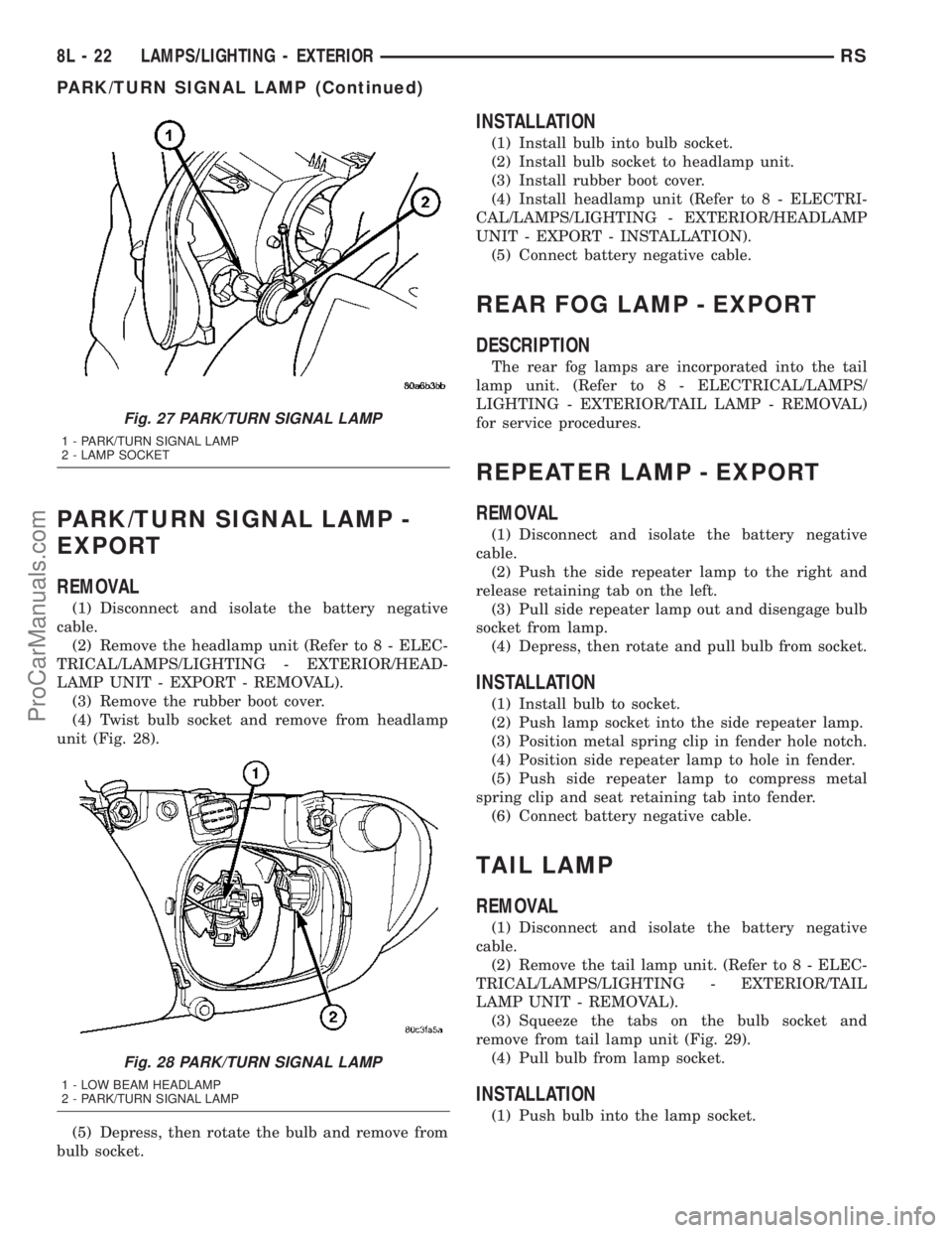
(4) Twist bulb socket and remove from headlamp
unit (Fig. 28).
(5) Depress, then rotate the bulb and remove from
bulb socket.
INSTALLATION
(1) Install bulb into bulb socket.
(2) Install bulb socket to headlamp unit.
(3) Install rubber boot cover.
(4) Install headlamp unit (Refer to 8 - ELECTRI-
CAL/LAMPS/LIGHTING - EXTERIOR/HEADLAMP
UNIT - EXPORT - INSTALLATION).
(5) Connect battery negative cable.
REAR FOG LAMP - EXPORT
DESCRIPTION
The rear fog lamps are incorporated into the tail
lamp unit. (Refer to 8 - ELECTRICAL/LAMPS/
LIGHTING - EXTERIOR/TAIL LAMP - REMOVAL)
for service procedures.
REPEATER LAMP - EXPORT
REMOVAL
(1) Disconnect and isolate the battery negative
cable.
(2) Push the side repeater lamp to the right and
release retaining tab on the left.
(3) Pull side repeater lamp out and disengage bulb
socket from lamp.
(4) Depress, then rotate and pull bulb from socket.
INSTALLATION
(1) Install bulb to socket.
(2) Push lamp socket into the side repeater lamp.
(3) Position metal spring clip in fender hole notch.
(4) Position side repeater lamp to hole in fender.
(5) Push side repeater lamp to compress metal
spring clip and seat retaining tab into fender.
(6) Connect battery negative cable.
TAIL LAMP
REMOVAL
(1) Disconnect and isolate the battery negative
cable.
(2) Remove the tail lamp unit. (Refer to 8 - ELEC-
TRICAL/LAMPS/LIGHTING - EXTERIOR/TAIL
LAMP UNIT - REMOVAL).
(3) Squeeze the tabs on the bulb socket and
remove from tail lamp unit (Fig. 29).
(4) Pull bulb from lamp socket.
INSTALLATION
(1) Push bulb into the lamp socket.
Fig. 27 PARK/TURN SIGNAL LAMP
1 - PARK/TURN SIGNAL LAMP
2 - LAMP SOCKET
Fig. 28 PARK/TURN SIGNAL LAMP
1 - LOW BEAM HEADLAMP
2 - PARK/TURN SIGNAL LAMP
8L - 22 LAMPS/LIGHTING - EXTERIORRS
PARK/TURN SIGNAL LAMP (Continued)
ProCarManuals.com
Page 438 of 2177
(2) Install bulb socket into the tail lamp unit.
Ensure that both retaining tabs engage with an audi-
ble click.
(3) Install the tail lamp unit. (Refer to 8 - ELEC-
TRICAL/LAMPS/LIGHTING - EXTERIOR/TAIL
LAMP UNIT - INSTALLATION).
(4) Reconnect the battery negative cable.
TAIL LAMP - EXPORT
REMOVAL
(1) Disconnect and isolate the battery negative
cable.
(2) Remove the tail lamp unit (Refer to 8 - ELEC-
TRICAL/LAMPS/LIGHTING - EXTERIOR/TAIL
LAMP UNIT - REMOVAL).
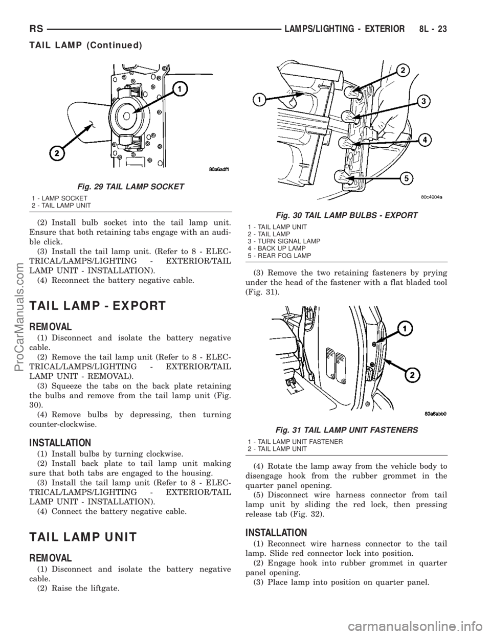
(3) Squeeze the tabs on the back plate retaining
the bulbs and remove from the tail lamp unit (Fig.
30).
(4) Remove bulbs by depressing, then turning
counter-clockwise.
INSTALLATION
(1) Install bulbs by turning clockwise.
(2) Install back plate to tail lamp unit making
sure that both tabs are engaged to the housing.
(3) Install the tail lamp unit (Refer to 8 - ELEC-
TRICAL/LAMPS/LIGHTING - EXTERIOR/TAIL
LAMP UNIT - INSTALLATION).
(4) Connect the battery negative cable.
TAIL LAMP UNIT
REMOVAL
(1) Disconnect and isolate the battery negative
cable.
(2) Raise the liftgate.(3) Remove the two retaining fasteners by prying
under the head of the fastener with a flat bladed tool
(Fig. 31).
(4) Rotate the lamp away from the vehicle body to
disengage hook from the rubber grommet in the
quarter panel opening.
(5) Disconnect wire harness connector from tail
lamp unit by sliding the red lock, then pressing
release tab (Fig. 32).
INSTALLATION
(1) Reconnect wire harness connector to the tail
lamp. Slide red connector lock into position.
(2) Engage hook into rubber grommet in quarter
panel opening.
(3) Place lamp into position on quarter panel.
Fig. 29 TAIL LAMP SOCKET
1 - LAMP SOCKET
2 - TAIL LAMP UNIT
Fig. 30 TAIL LAMP BULBS - EXPORT
1 - TAIL LAMP UNIT
2 - TAIL LAMP
3 - TURN SIGNAL LAMP
4 - BACK UP LAMP
5 - REAR FOG LAMP
Fig. 31 TAIL LAMP UNIT FASTENERS
1 - TAIL LAMP UNIT FASTENER
2 - TAIL LAMP UNIT
RSLAMPS/LIGHTING - EXTERIOR8L-23
TAIL LAMP (Continued)
ProCarManuals.com
Page 440 of 2177

LAMPS/LIGHTING - INTERIOR
TABLE OF CONTENTS
page page
LAMPS/LIGHTING - INTERIOR
SPECIFICATIONS
INTERIOR LAMPS.....................25
CENTER CONSOLE LAMP SWITCH
REMOVAL.............................26
INSTALLATION.........................26
CLUSTER ILLUMINATION LAMPS
REMOVAL.............................26
INSTALLATION.........................26
COURTESY LAMP
REMOVAL.............................26
INSTALLATION.........................26
DOME/CARGO LAMP
REMOVAL.............................26INSTALLATION.........................26
GLOVE BOX LAMP SWITCH
REMOVAL.............................26
INSTALLATION.........................26
LIFTGATE LAMP
REMOVAL.............................27
INSTALLATION.........................27
READING LAMP
REMOVAL.............................27
INSTALLATION.........................28
VANITY LAMP
REMOVAL.............................28
INSTALLATION.........................28
LAMPS/LIGHTING - INTERIOR
SPECIFICATIONS
INTERIOR LAMPS
BULB APPLICATION TABLE
LAMP BULB
ABS LED
AIRBAG LED
ALARM SET PC74
AUTOSTICK VFD*
BRAKE SYSTEM
WARNINGLED
CONSOLE 194
CRUISE INDICATOR VFD*
DOME/RAIL LAMPS 578
DOOR AJAR INDICATOR LED
DOOR COURTESY
LAMP578
FRONT DOOR
COURTESY567
GLOVE BOX 194
HIGH BEAM INDICATOR
(BASE CLUSTER)LED
HIGH BEAM INDICATOR PC74
LAMP BULB
CLUSTER
ILLUMINATIONPC74
LIFTGATE 578
LIFTGATE AJAR LED
LOW FUEL INDICATOR LED
LOW WASHER FLUID
INDICATORLED
MIL (BASE CLUSTER) LED
MIL PC74
OIL INDICATOR (BASE
CLUSTER)LED
OIL INDICATOR PC74
OVERHEAD CONSOLE
READINGPC579
OVERDRIVE OFF
INDICATORVFD*
READING 578
SEAT BELT INDICATOR LED
TEMPERATURE
INDICATORLED
TRAC OFF INDICATOR VFD*
TURN SIGNAL
INDICATOR (BASE
CLUSTER)LED
TURN SIGNAL
INDICATORPC74
VISOR VANITY 6501966
RSLAMPS/LIGHTING - INTERIOR8L-25
ProCarManuals.com