wheel alignment CHRYSLER CARAVAN 2003 Service Manual
[x] Cancel search | Manufacturer: CHRYSLER, Model Year: 2003, Model line: CARAVAN, Model: CHRYSLER CARAVAN 2003Pages: 2177, PDF Size: 59.81 MB
Page 44 of 2177
SUSPENSION
TABLE OF CONTENTS
page page
FRONT SUSPENSION.....................1
REAR SUSPENSION......................26WHEEL ALIGNMENT.....................46
FRONT SUSPENSION
TABLE OF CONTENTS
page page
FRONT SUSPENSION
DESCRIPTION - FRONT SUSPENSION.......2
OPERATION - FRONT SUSPENSION.........2
STANDARD PROCEDURE - LUBRICATION....2
SPECIFICATIONS
FRONT SUSPENSION FASTENER TORQUE . . 3
SPECIAL TOOLS
FRONT SUSPENSION...................3
BUSHINGS
REMOVAL - STABILIZER BAR CUSHION......4
INSTALLATION - STABILIZER BAR CUSHION . . . 4
HUB / BEARING
DESCRIPTION..........................5
OPERATION............................5
DIAGNOSIS AND TESTING - HUB AND
BEARING............................5
REMOVAL.............................5
INSTALLATION..........................5
KNUCKLE
DESCRIPTION..........................6
OPERATION............................7
REMOVAL - STEERING KNUCKLE...........7
INSPECTION - STEERING KNUCKLE.........9
INSTALLATION - STEERING KNUCKLE.......9
LOWER BALL JOINT
DESCRIPTION.........................10
OPERATION...........................10
DIAGNOSIS AND TESTING - LOWER BALL
JOINT..............................10
LOWER BALL JOINT SEAL BOOT
DESCRIPTION - EXPORT.................10
REMOVAL
REMOVAL - BALL JOINT SEAL BOOT......11
REMOVAL - EXPORT...................11INSTALLATION
INSTALLATION - BALL JOINT SEAL BOOT . . 11
INSTALLATION - EXPORT...............12
LOWER CONTROL ARM
DESCRIPTION.........................12
OPERATION...........................12
REMOVAL - LOWER CONTROL ARM........12
DISASSEMBLY
DISASSEMBLY - LOWER CONTROL ARM
(REAR BUSHING - STANDARD)..........13
DISASSEMBLY - LOWER CONTROL ARM
(REAR BUSHING - HYDRO).............14
INSPECTION - LOWER CONTROL ARM......14
ASSEMBLY
ASSEMBLY - LOWER CONTROL ARM
(REAR BUSHING - STANDARD)..........14
ASSEMBLY - LOWER CONTROL ARM
(REAR BUSHING - HYDRO).............14
INSTALLATION - LOWER CONTROL ARM....15
STABILIZER BAR
DESCRIPTION.........................16
OPERATION...........................16
REMOVAL.............................17
INSPECTION..........................17
INSTALLATION.........................17
STRUT
DESCRIPTION - STRUT ASSEMBLY.........19
OPERATION - STRUT ASSEMBLY..........19
DIAGNOSIS AND TESTING - STRUT
ASSEMBLY..........................20
REMOVAL - STRUT ASSEMBLY............20
DISASSEMBLY - STRUT ASSEMBLY........21
ASSEMBLY - STRUT ASSEMBLY...........23
INSTALLATION - STRUT ASSEMBLY........25
RSSUSPENSION2-1
ProCarManuals.com
Page 49 of 2177
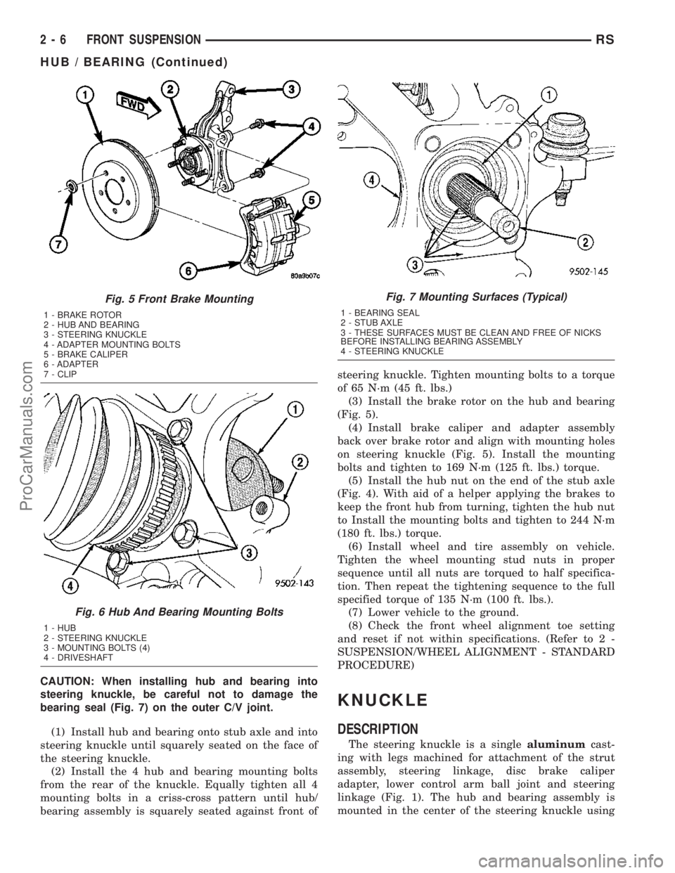
CAUTION: When installing hub and bearing into
steering knuckle, be careful not to damage the
bearing seal (Fig. 7) on the outer C/V joint.
(1) Install hub and bearing onto stub axle and into
steering knuckle until squarely seated on the face of
the steering knuckle.
(2) Install the 4 hub and bearing mounting bolts
from the rear of the knuckle. Equally tighten all 4
mounting bolts in a criss-cross pattern until hub/
bearing assembly is squarely seated against front ofsteering knuckle. Tighten mounting bolts to a torque
of 65 N´m (45 ft. lbs.)
(3) Install the brake rotor on the hub and bearing
(Fig. 5).
(4) Install brake caliper and adapter assembly
back over brake rotor and align with mounting holes
on steering knuckle (Fig. 5). Install the mounting
bolts and tighten to 169 N´m (125 ft. lbs.) torque.
(5) Install the hub nut on the end of the stub axle
(Fig. 4). With aid of a helper applying the brakes to
keep the front hub from turning, tighten the hub nut
to Install the mounting bolts and tighten to 244 N´m
(180 ft. lbs.) torque.
(6) Install wheel and tire assembly on vehicle.
Tighten the wheel mounting stud nuts in proper
sequence until all nuts are torqued to half specifica-
tion. Then repeat the tightening sequence to the full
specified torque of 135 N´m (100 ft. lbs.).
(7) Lower vehicle to the ground.
(8) Check the front wheel alignment toe setting
and reset if not within specifications. (Refer to 2 -
SUSPENSION/WHEEL ALIGNMENT - STANDARD
PROCEDURE)
KNUCKLE
DESCRIPTION
The steering knuckle is a singlealuminumcast-
ing with legs machined for attachment of the strut
assembly, steering linkage, disc brake caliper
adapter, lower control arm ball joint and steering
linkage (Fig. 1). The hub and bearing assembly is
mounted in the center of the steering knuckle using
Fig. 5 Front Brake Mounting
1 - BRAKE ROTOR
2 - HUB AND BEARING
3 - STEERING KNUCKLE
4 - ADAPTER MOUNTING BOLTS
5 - BRAKE CALIPER
6 - ADAPTER
7 - CLIP
Fig. 6 Hub And Bearing Mounting Bolts
1 - HUB
2 - STEERING KNUCKLE
3 - MOUNTING BOLTS (4)
4 - DRIVESHAFT
Fig. 7 Mounting Surfaces (Typical)
1 - BEARING SEAL
2 - STUB AXLE
3 - THESE SURFACES MUST BE CLEAN AND FREE OF NICKS
BEFORE INSTALLING BEARING ASSEMBLY
4 - STEERING KNUCKLE
2 - 6 FRONT SUSPENSIONRS
HUB / BEARING (Continued)
ProCarManuals.com
Page 53 of 2177
(6) Install tie rod end into knuckle steering arm.
Start nut onto stud of tie rod end. While holding stud
of tie rod end stationary using a socket (Fig. 11),
tighten tie rod end to steering knuckle attaching nut.
Tighten the tie rod end nut to a torque of 75 N´m (55
ft. lbs.).
(7) If equipped with antilock brakes, install wheel
speed sensor and mounting bolt on steering knuckle
(Fig. 13). Tighten the speed sensor bolt to a torque of
7 N´m (60 in. lbs.).
(8) Install brake rotor on hub and bearing (Fig. 9).
(9) Install disc brake caliper and adapter assembly
on steering knuckle. Install adapter amounting bolts
and tighten to 169 N´m (125 ft. lbs.).
(10) Clean any debris from the threads of the
outer C/V joint stub axle.
(11) Install the washer and hub nut on stub axle.
(12) Have a helper apply the vehicle's brakes to
keep hub from turning, then tighten hub nut to a
torque of 244 N´m (180 ft. lbs.).
(13) Install the spring wave washer on the end of
the stub axle.
(14) Install the hub nut lock, and anewcotter pin
(Fig. 8). Wrap cotter pin prongs tightly around the
hub nut lock.
(15) Install wheel and tire assembly. Install and
tighten the wheel mounting nuts in proper sequence
until all nuts are torqued to half the required speci-
fication. Then repeat the tightening sequence to the
full specified torque of 135 N´m (100 ft. lbs.).
(16) Lower vehicle.
(17) Set front wheel alignment camber and toe as
necessary. (Refer to 2 - SUSPENSION/WHEEL
ALIGNMENT - STANDARD PROCEDURE)
LOWER BALL JOINT
DESCRIPTION
The ball joint is an integral part of the lower con-
trol arm (Fig. 1). The ball joint has a tapered stud
that is pressed into the aluminum knuckle. The ball
joint stud is threaded on the end for a retainer nut.
The ball joint has a non-vented seal boot. The seal
boot has an integrated heat shield.
The ball joint used in the lower control arm of this
vehicle is a sealed-for-life ball joint and requires no
maintenance lubrication. The ball joint has been
lubricated-for-life during the manufacturing process.
A special fitting cap is installed on the fill port. This
cap must not be removed and replaced with a com-
mon zirc fitting. The special cap is there to eliminate
the possibility of lubrication latter during the ball
joints life, thus damaging the non-vented seal boot.
NOTE: The ball joint does not require any type of
additional lubrication for the life of the vehicle. No
attempt should be made to ever add any lubrication
to the lower ball joint.
OPERATION
The ball joint is a pivotal joint on the lower control
arm that allows the knuckle to move up and down,
and turn with ease.
DIAGNOSIS AND TESTING - LOWER BALL
JOINT
With the weight of the vehicle resting on the road
wheels, grasp the special fitting cap on the bottom of
the ball joint and with no mechanical assistance or
added force, attempt to rotate the grease fitting.
If the ball joint is worn, the grease fitting will
rotate easily. If movement is noted, replacement of
the control arm is recommended.
LOWER BALL JOINT SEAL
BOOT
DESCRIPTION - EXPORT
The lower ball joint seal boot is a two piece unit. It
consists of the seal boot, plus a separate shield that
is located in a groove at the top of the seal boot.
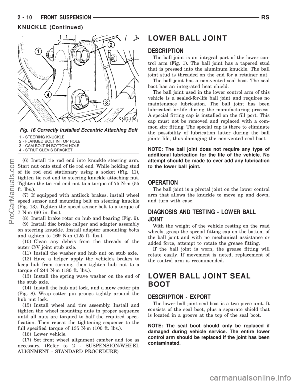
NOTE: The seal boot should only be replaced if
damaged during vehicle service. The entire lower
control arm should be replaced if the joint has been
contaminated.
Fig. 16 Correctly Installed Eccentric Attaching Bolt
1 - STEERING KNUCKLE
2 - FLANGED BOLT IN TOP HOLE
3 - CAM BOLT IN BOTTOM HOLE
4 - STRUT CLEVIS BRACKET
2 - 10 FRONT SUSPENSIONRS
KNUCKLE (Continued)
ProCarManuals.com
Page 59 of 2177

153 N´m (113 ft. lbs.). Tighten the M-12 size bolts to
a torque of 106 N´m (78 ft. lbs.).
(4) Install the lower control arm rear bushing
retainer bolts through reinforcement on each side of
each lower control arm rear bushing. Tighten these
M-10 size bolts to a torque of 61 N´m (45 ft. lbs.).
(5) Install the two bolts and bushings attaching
the reinforcement and rear of cradle crossmember to
body of vehicle (Fig. 22). Tighten bolts to a torque of
163 N´m (120 ft. lbs.).
(6) Install the power steering cooler (Fig. 21).
Tighten bolts to a torque of 11 N´m (100 in. lbs.).
(7) Reinstall steering knuckle, brake rotor and cal-
iper. (Refer to 2 - SUSPENSION/FRONT/KNUCKLE
- INSTALLATION)
CAUTION: When locating jack stands under lower
control arms, do not place the jack stands under
the ball joints (Fig. 30).
(8) Position jack stands under the lower control
arms as close to the ball joints as possible (Fig. 30).
Lower the vehicle onto the jack stands until the jack
stands are supporting the total weight of the vehicle.
(9) Tighten front lower control arm pivot bolt to a
torque of 183 N´m (135 ft. lbs.).
(10) Install the wheel and tire assembly. Install
and tighten the wheel mounting stud nuts in proper
sequence until all nuts are torqued to half specifica-
tion. Then repeat the tightening sequence to the full
specified torque of 135 N´m (100 ft. lbs.).
(11) Raise vehicle, remove jack stands and lower
vehicle to the ground.(12) Perform front wheel alignment as necessary.
(Refer to 2 - SUSPENSION/WHEEL ALIGNMENT -
STANDARD PROCEDURE)
STABILIZER BAR
DESCRIPTION
The stabilizer bar interconnects both front struts of
the vehicle and is attached to the front crossmember
(Fig. 1).
Attachment of the stabilizer bar to the front cross-
member is through 2 rubber-isolator cushion bush-
ings and retainers. A double ball jointed stabilizer
bar link is used to attach each end of the stabilizer
bar to the front strut assemblies. All parts of the sta-
bilizer bar are replaceable as individual components.
The stabilizer bar to front crossmember cushion
bushings are split for easy removal and installation.
The split in the bushings should be positioned toward
the rear of the vehicle, with the square corner facing
down, when the stabilizer bar is installed.
OPERATION
Jounce and rebound movements affecting one
wheel are partially transmitted to the opposite wheel
of the vehicle through the stabilizer bar. This helps
to minimize the body roll of the vehicle during sus-
pension movement.
Connecting the stabilizer bar links to the strut
assemblies helps reduce the fore-and-aft rate of the
stabilizer bar from the rest of the front suspension.
Fig. 29 Lower Control Arm Bushing Pivot Bolt
Correctly Installed
1 - PIVOT BOLT
2 - LOWER CONTROL ARM
3 - FRONT SUSPENSION CRADLE CROSSMEMBER
Fig. 30 Jack Stands Supporting Vehicle Weight
1 - LOWER CONTROL ARMS
2 - BALL JOINT
3 - JACK STANDS
4 - BALL JOINT
2 - 16 FRONT SUSPENSIONRS
LOWER CONTROL ARM (Continued)
ProCarManuals.com
Page 89 of 2177
WHEEL ALIGNMENT
TABLE OF CONTENTS
page page
WHEEL ALIGNMENT
DESCRIPTION - WHEEL ALIGNMENT.......46
DIAGNOSIS AND TESTING - SUSPENSION
AND STEERING......................49
STANDARD PROCEDURE
STANDARD PROCEDURE - WHEEL
ALIGNMENT.........................51STANDARD PROCEDURE - CURB HEIGHT
MEASUREMENT......................54
SPECIFICATIONS
WHEEL ALIGNMENT...................55
WHEEL ALIGNMENT
DESCRIPTION - WHEEL ALIGNMENT
Vehicle wheel alignment is the positioning of all
interrelated front and rear suspension angles. These
angles affect the handling and steering of the vehicle
when it is in motion. Proper wheel alignment is
essential for efficient steering, good directional stabil-
ity, and proper tire wear.
The method of checking a vehicle's front and rear
wheel alignment varies depending on the manufac-
turer and type of equipment used. The manufactur-
er's instructions should always be followed to ensure
accuracy of the alignment, except when
DaimlerChrysler Corporation's wheel alignment spec-
ifications differ.
On this vehicle, the suspension angles that can be
adjusted are as follows:
²Front Camber (with camber bolt package and
standard procedure)
²Front Toe
Check the wheel alignment and make all wheel
alignment adjustments with the vehicle standing at
its proper curb height specification. Curb height is
the normal riding height of the vehicle. It is mea-
sured from a certain point on the vehicle to the
ground or a designated area while the vehicle is sit-
ting on a flat, level surface. Refer to Curb Height
Measurement in this section for additional informa-
tion.
Typical wheel alignment angles and measurements
are described in the following paragraphs.
CAMBER
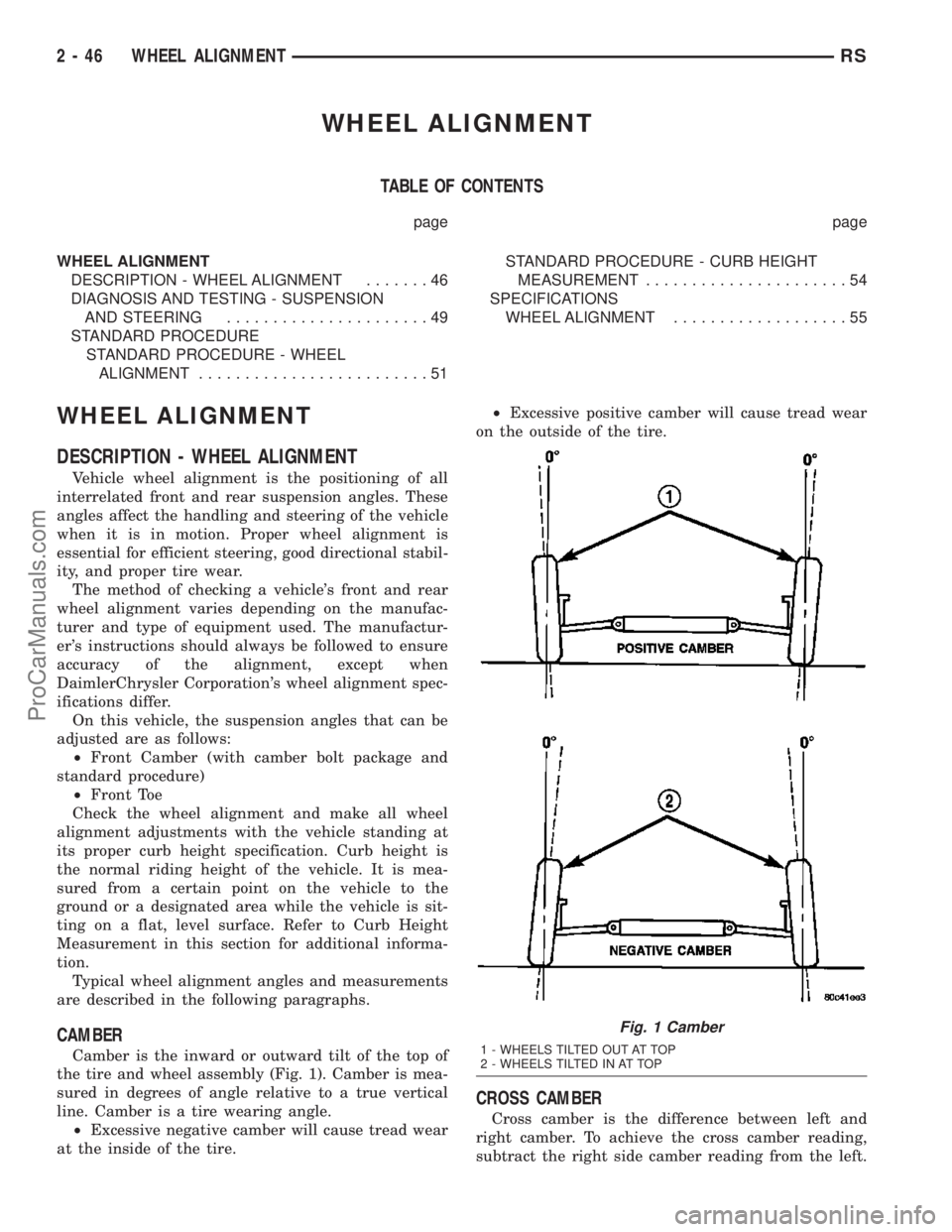
Camber is the inward or outward tilt of the top of
the tire and wheel assembly (Fig. 1). Camber is mea-
sured in degrees of angle relative to a true vertical
line. Camber is a tire wearing angle.
²Excessive negative camber will cause tread wear
at the inside of the tire.²Excessive positive camber will cause tread wear
on the outside of the tire.
CROSS CAMBER
Cross camber is the difference between left and
right camber. To achieve the cross camber reading,
subtract the right side camber reading from the left.
Fig. 1 Camber
1 - WHEELS TILTED OUT AT TOP
2 - WHEELS TILTED IN AT TOP
2 - 46 WHEEL ALIGNMENTRS
ProCarManuals.com
Page 90 of 2177
For example, if the left camber is +0.3É and the right
camber is 0.0É, the cross camber would be +0.3É.
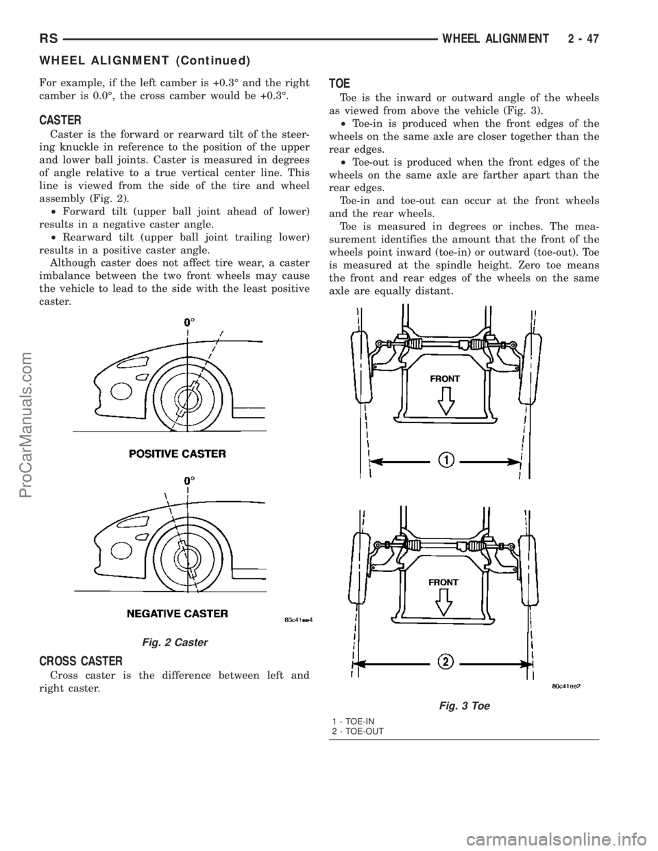
CASTER
Caster is the forward or rearward tilt of the steer-
ing knuckle in reference to the position of the upper
and lower ball joints. Caster is measured in degrees
of angle relative to a true vertical center line. This
line is viewed from the side of the tire and wheel
assembly (Fig. 2).
²Forward tilt (upper ball joint ahead of lower)
results in a negative caster angle.
²Rearward tilt (upper ball joint trailing lower)
results in a positive caster angle.
Although caster does not affect tire wear, a caster
imbalance between the two front wheels may cause
the vehicle to lead to the side with the least positive
caster.
CROSS CASTER
Cross caster is the difference between left and
right caster.
TOE
Toe is the inward or outward angle of the wheels
as viewed from above the vehicle (Fig. 3).
²Toe-in is produced when the front edges of the
wheels on the same axle are closer together than the
rear edges.
²Toe-out is produced when the front edges of the
wheels on the same axle are farther apart than the
rear edges.
Toe-in and toe-out can occur at the front wheels
and the rear wheels.
Toe is measured in degrees or inches. The mea-
surement identifies the amount that the front of the
wheels point inward (toe-in) or outward (toe-out). Toe
is measured at the spindle height. Zero toe means
the front and rear edges of the wheels on the same
axle are equally distant.
Fig. 2 Caster
Fig. 3 Toe
1 - TOE-IN
2 - TOE-OUT
RSWHEEL ALIGNMENT2-47
WHEEL ALIGNMENT (Continued)
ProCarManuals.com
Page 91 of 2177

TOE-OUT ON TURNS
Toe-out on turns is the relative positioning of the
front wheels while steering through a turn (Fig. 4).
This compensates for each front wheel's turning
radius. As the vehicle encounters a turn, the out-
board wheel must travel in a larger radius circle
than the inboard wheel. The steering system is
designed to make each wheel follow its particular
radius circle. To accomplish this, the front wheels
must progressively toe outward as the steering is
turned from center. This eliminates tire scrubbing
and undue tire wear when steering a vehicle through
a turn.
DYNAMIC TOE PATTERN
Dynamic toe pattern is the inward and outward toe
movement of the front and rear tires through the
suspension's jounce and rebound travel. As the vehi-
cle's suspension moves up and down, the toe pattern
varies. Toe pattern is critical in controlling the direc-
tional stability of the vehicle while in motion. Front
and rear dynamic toe pattern is preset by the factory
at the time the vehicle is assembled.
It is not necessary to check or adjust front or rear
dynamic toe pattern when doing a normal wheel
alignment. The only time dynamic toe pattern needs
to be checked or adjusted is if the frame of the vehi-
cle has been damaged.
STEERING AXIS INCLINATION (S. A. I.)
Steering axis inclination is the angle between a
true vertical line starting at the center of the tire at
the road contact point and a line drawn through the
center of the upper ball joint (or strut) and the lower
ball joint (Fig. 5). S.A.I. is built into the vehicle and
is not an adjustable angle. If S.A.I. is not within
specifications, a bent or damaged suspension compo-
nent may be the cause.
INCLUDED ANGLE (I. A.)
Included angle is the sum of the S.A.I. angle plus
or minus the camber angle, depending on whether or
not the wheel has positive or negative camber (Fig.
5). If camber is positive, add the camber angle to the
S.A.I. angle. If camber is negative, subtract the cam-
ber angle from the S.A.I. angle. Included angle is not
adjustable, but can be used to diagnose a frame mis-
alignment or bent suspension component (spindle,
strut).
Fig. 4 Toe-Out On Turns
1 - TOE-OUT ON TURNS
Fig. 5 S.A.I. and I.A.
1 - S.A.I.
2 - CAMBER
3 - I.A.
2 - 48 WHEEL ALIGNMENTRS
WHEEL ALIGNMENT (Continued)
ProCarManuals.com
Page 92 of 2177

THRUST ANGLE
Thrust angle is the averaged direction the rear
wheels are pointing in relation to the vehicle's center
line (Fig. 6). The presence of negative or positive
thrust angle causes the rear tires to track improperly
to the left or right of the front tires (dog tracking).
²Negative thrust angle means the rear tires are
tracking to the left of the front tires.
²Positive thrust angle means the rear tires are
tracking to the right of the front tires.
Improper tracking can cause undue tire wear, a
lead or pull and a crooked steering wheel. Excessive
thrust angle can usually be corrected by adjusting
the rear wheel toe so that each wheel has one-half of
the total toe measurement.
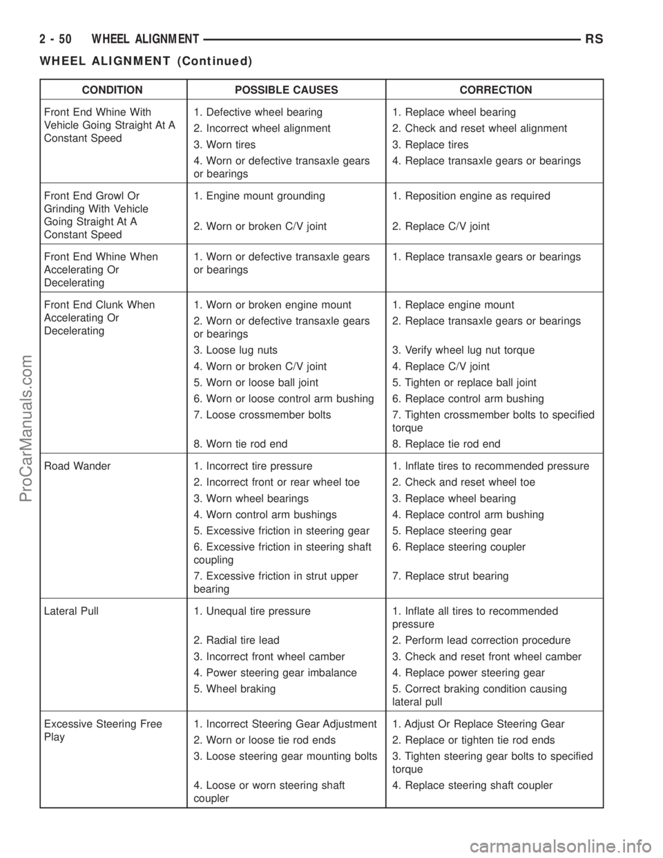
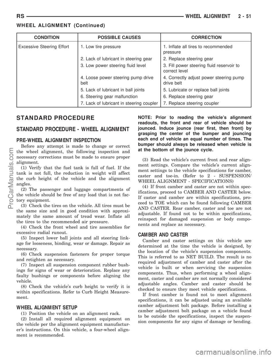
DIAGNOSIS AND TESTING - SUSPENSION AND STEERING
CONDITION POSSIBLE CAUSES CORRECTION
Front End Whine On Turns 1. Defective wheel bearing 1. Replace wheel bearing
2. Incorrect wheel alignment 2. Check and reset wheel alignment
3. Worn tires 3. Replace tires
Front End Growl Or
Grinding On Turns1. Defective wheel bearing 1. Replace wheel bearing
2. Engine mount grounding 2. Check for motor mount hitting frame rail
and reposition engine as required
3. Worn or broken C/V joint 3. Replace C/V joint
4. Loose wheel lug nuts 4. Verify wheel lug nut torque
5. Incorrect wheel alignment 5. Check and reset wheel alignment
6. Worn tires 6. Replace tires
7. Front strut pin in upper strut mount 7. Replace the front strut upper mount and
bearing
Front End Clunk Or Snap
On Turns1. Loose lug nuts 1. Verify wheel lug nut torque
2. Worn or broken C/V joint 2. Replace C/V joint
3. Worn or loose tie rod 3. Tighten or replace tie rod end
4. Worn or loose ball joint 4. Tighten or replace ball joint
5. Worn/loose control arm bushing 5. Replace control arm bushing
6. Loose stabilizer bar. 6. Tighten stabilizer bar to specified torque
7. Loose strut mount to body
attachment7. Tighten strut attachment to specified
torque
8. Loose crossmember bolts 8. Tighten crossmember bolts to specified
torque
Fig. 6 Thrust Angle
RSWHEEL ALIGNMENT2-49
WHEEL ALIGNMENT (Continued)
ProCarManuals.com
Page 93 of 2177
CONDITION POSSIBLE CAUSES CORRECTION
Front End Whine With
Vehicle Going Straight At A
Constant Speed1. Defective wheel bearing 1. Replace wheel bearing
2. Incorrect wheel alignment 2. Check and reset wheel alignment
3. Worn tires 3. Replace tires
4. Worn or defective transaxle gears
or bearings4. Replace transaxle gears or bearings
Front End Growl Or
Grinding With Vehicle
Going Straight At A
Constant Speed1. Engine mount grounding 1. Reposition engine as required
2. Worn or broken C/V joint 2. Replace C/V joint
Front End Whine When
Accelerating Or
Decelerating1. Worn or defective transaxle gears
or bearings1. Replace transaxle gears or bearings
Front End Clunk When
Accelerating Or
Decelerating1. Worn or broken engine mount 1. Replace engine mount
2. Worn or defective transaxle gears
or bearings2. Replace transaxle gears or bearings
3. Loose lug nuts 3. Verify wheel lug nut torque
4. Worn or broken C/V joint 4. Replace C/V joint
5. Worn or loose ball joint 5. Tighten or replace ball joint
6. Worn or loose control arm bushing 6. Replace control arm bushing
7. Loose crossmember bolts 7. Tighten crossmember bolts to specified
torque
8. Worn tie rod end 8. Replace tie rod end
Road Wander 1. Incorrect tire pressure 1. Inflate tires to recommended pressure
2. Incorrect front or rear wheel toe 2. Check and reset wheel toe
3. Worn wheel bearings 3. Replace wheel bearing
4. Worn control arm bushings 4. Replace control arm bushing
5. Excessive friction in steering gear 5. Replace steering gear
6. Excessive friction in steering shaft
coupling6. Replace steering coupler
7. Excessive friction in strut upper
bearing7. Replace strut bearing
Lateral Pull 1. Unequal tire pressure 1. Inflate all tires to recommended
pressure
2. Radial tire lead 2. Perform lead correction procedure
3. Incorrect front wheel camber 3. Check and reset front wheel camber
4. Power steering gear imbalance 4. Replace power steering gear
5. Wheel braking 5. Correct braking condition causing
lateral pull
Excessive Steering Free
Play1. Incorrect Steering Gear Adjustment 1. Adjust Or Replace Steering Gear
2. Worn or loose tie rod ends 2. Replace or tighten tie rod ends
3. Loose steering gear mounting bolts 3. Tighten steering gear bolts to specified
torque
4. Loose or worn steering shaft
coupler4. Replace steering shaft coupler
2 - 50 WHEEL ALIGNMENTRS
WHEEL ALIGNMENT (Continued)
ProCarManuals.com
Page 94 of 2177
CONDITION POSSIBLE CAUSES CORRECTION
Excessive Steering Effort 1. Low tire pressure 1. Inflate all tires to recommended
pressure
2. Lack of lubricant in steering gear 2. Replace steering gear
3. Low power steering fluid level 3. Fill power steering fluid reservoir to
correct level
4. Loose power steering pump drive
belt4. Correctly adjust power steering pump
drive belt
5. Lack of lubricant in ball joints 5. Lubricate or replace ball joints
6. Steering gear malfunction 6. Replace steering gear
7. Lack of lubricant in steering coupler 7. Replace steering coupler
STANDARD PROCEDURE
STANDARD PROCEDURE - WHEEL ALIGNMENT
PRE-WHEEL ALIGNMENT INSPECTION
Before any attempt is made to change or correct
the wheel alignment, the following inspection and
necessary corrections must be made to ensure proper
alignment.
(1) Verify that the fuel tank is full of fuel. If the
tank is not full, the reduction in weight will affect
the curb height of the vehicle and the alignment
angles.
(2) The passenger and luggage compartments of
the vehicle should be free of any load that is not fac-
tory equipment.
(3) Check the tires on the vehicle. All tires must be
the same size and in good condition with approxi-
mately the same amount of tread wear. Inflate all
the tires to the recommended air pressure.
(4) Check the front wheel and tire assemblies for
excessive radial runout.
(5) Inspect lower ball joints and all steering link-
age for looseness, binding, wear or damage. Repair as
necessary.
(6) Check suspension fasteners for proper torque
and retighten as necessary.
(7) Inspect all suspension component rubber bush-
ings for signs of wear or deterioration. Replace any
faulty bushings or components before aligning the
vehicle.
(8) Check the vehicle's curb height to verify it is
within specifications. Refer to Curb Height Measure-
ment.
WHEEL ALIGNMENT SETUP
(1) Position the vehicle on an alignment rack.
(2) Install all required alignment equipment on
the vehicle per the alignment equipment manufactur-
er's instructions. On this vehicle, a four-wheel align-
ment is recommended.NOTE: Prior to reading the vehicle's alignment
readouts, the front and rear of vehicle should be
jounced. Induce jounce (rear first, then front) by
grasping the center of the bumper and jouncing
each end of vehicle an equal number of times. The
bumper should always be released when vehicle is
at the bottom of the jounce cycle.
(3) Read the vehicle's current front and rear align-
ment settings. Compare the vehicle's current align-
ment settings to the vehicle specifications for camber,
caster and toe-in. (Refer to 2 - SUSPENSION/
WHEEL ALIGNMENT - SPECIFICATIONS)
(4) If front camber and caster are not within spec-
ifications, proceed to CAMBER AND CASTER below.
If caster and camber are within specifications, pro-
ceed to TOE which can be found following CAMBER
AND CASTER. Rear camber, caster and toe are not
adjustable. If found not to be within specifications,
reinspect for damaged suspension or body compo-
nents and replace as necessary.
CAMBER AND CASTER
Camber and caster settings on this vehicle are
determined at the time the vehicle is designed, by
the location of the vehicle's suspension components.
This is referred to as NET BUILD. The result is no
required adjustment of camber and caster after the
vehicle is built or when servicing the suspension
components. Thus, when performing a wheel align-
ment, caster and camber are not normally considered
adjustable angles. Camber and caster should be
checked to ensure they meet vehicle specifications.
If front camber is found not to meet alignment
specifications, it can be adjusted using an available
camber adjustment bolt package. Before installing a
camber adjustment bolt package on a vehicle found
to be outside the specifications, inspect the suspen-
sion components for any signs of damage or bending.
RSWHEEL ALIGNMENT2-51
WHEEL ALIGNMENT (Continued)
ProCarManuals.com