turn signal CHRYSLER PACIFICA HYBRID 2022 User Guide
[x] Cancel search | Manufacturer: CHRYSLER, Model Year: 2022, Model line: PACIFICA HYBRID, Model: CHRYSLER PACIFICA HYBRID 2022Pages: 384, PDF Size: 23.92 MB
Page 68 of 384
66GETTING TO KNOW YOUR VEHICLE
From the O (off) position, rotate the headlight switch
clockwise to the first detent for parking light and
instrument panel light operation. Rotate the
headlight switch to the second detent for headlight,
parking light and instrument panel operation.
NOTE:For vehicles sold in Canada, rotate the headlight
switch clockwise from the parking light and
instrument panel light position to the first detent to
turn on the headlights also. Rotate to the second
detent, AUTO position, to turn on automatic head -
lights, parking lights, and instrument panel lights.
DAYTIME RUNNING LIGHTS (DRLS) —
I
F EQUIPPED
The headlights or LED light bars on your vehicle will
illuminate when the engine is started. This
provides a constant lights on condition until the
ignition is placed in the OFF position. If the parking
brake is applied, the Daytime Running Lights
(DRLs) will turn off.
NOTE:
For vehicles sold in Canada, the Daytime
Running Lights will automatically deactivate
when the front fog lights are turned on.
If allowed by law in the country in which the
vehicle was purchased, the Daytime Running
Lights can be turned on and off using the Ucon -
nect system Ú page 188.
On some vehicles, the Daytime Running Lights
may deactivate, or reduce intensity, on one side
of the vehicle (when a turn signal is activated on
that side), or on both sides of the vehicle (when
the hazard warning lights are activated).
HIGH/LOW BEAM SWITCH
Push the multifunction lever toward the instrument
panel to switch the headlights to high beams.
Pulling the multifunction lever back will turn the
low beams on.
AUTOMATIC HIGH BEAM — IF EQUIPPED
The Automatic High Beam system provides
increased forward lighting at night by automatically
controlling the high beams through the use of a
camera mounted on the windshield. This camera
detects vehicle specific light and automatically
switches from high beams to low beams until the
approaching vehicle is out of view.
NOTE:Broken, muddy, or obstructed headlights and tail -
lights of vehicles in the field of view will cause
headlights to remain on longer (closer to the
vehicle). Also, dirt, film and other obstructions on
the windshield or camera lens will cause the
system to function improperly.
To Activate
1. Select “Auto Dim High Beams” through the Uconnect system to enable the feature
Ú
page 188.
2. Rotate the headlight switch clockwise to the AUTO position.
3. Push the multifunction lever away from you to switch the headlights to the high beam
position. Refer to “Multifunction Lever” in this
section for further information.
NOTE:This system will not activate until the vehicle is at,
or above 16 mph (25 km/h).
To Deactivate
Perform either of the following steps to deactivate
the Automatic High Beam system.
1. Deselect “Auto Dim High Beams” through the Uconnect system
Ú
page 188.
2. Pull the multifunction lever toward you to switch the headlights from the high beam to
the low beam position.
3. Rotate the headlight switch counterclockwise from the AUTO to the on position.
NOTE:Once active, the Automatic High Beam system will
stop functioning below 12 mph (20 km/h).
22_RUP_OM_EN_USC_t.book Page 66
Page 69 of 384
GETTING TO KNOW YOUR VEHICLE67
FLASH-TO-PASS
You can signal another vehicle with your headlights
by lightly pulling the multifunction lever toward you.
This will cause the high beam headlights to turn on,
and remain on, until the lever is released.
AUTOMATIC HEADLIGHTS — IF EQUIPPED
This system automatically turns your headlights on
or off based on ambient light levels. To turn the
system on, turn the headlight switch to the extreme
clockwise position aligning the indicator with the
AUTO on the headlight switch. When the system is
on, the Headlight Time Delay feature is also on.
This means your headlights will stay on for up to
90 seconds after the ignition is placed in the OFF
position. To turn the automatic system off, move
the headlight switch out of the AUTO position.
NOTE:The engine must be running before the headlights
will come on in the Automatic mode.
HEADLIGHTS ON WITH WIPERS —
I
F EQUIPPED
When your headlights are in the AUTO mode and
the engine is running, the headlights will
automatically turn on when the wiper system is
also turned on. Headlights on when windshield
wipers are on may be found on vehicles equipped
with an automatic headlight system.
NOTE:The Headlights with Wipers feature can be turned
on or off through the Uconnect system
Ú page 188.
HEADLIGHT TIME DELAY — IF EQUIPPED
This feature provides the safety of headlight
illumination for up to 90 seconds after exiting your
vehicle.
To activate the delay feature, place the ignition in
the OFF position while the headlights are still on.
The 90 second delay interval begins when
headlight switch is turned off. If the headlights or
parking lights are turned back on or the ignition is
placed in the ON position, the delay will be
cancelled. When exiting the vehicle the driver can choose to
have the headlights remain on for 30, 60, or
90 seconds or not remain on. You can change
the timer setting through the Uconnect system
Ú
page 188.
If the headlights are turned off before the ignition,
they will turn off in the normal manner.
NOTE:The headlights must be turned off within
45 seconds of placing the ignition in the OFF
position to activate this feature.
LIGHTS-ON REMINDER
If the headlights or the parking lights are left on
after the ignition is placed in the OFF position, the
vehicle will chime when the driver's door is opened.
2
22_RUP_OM_EN_USC_t.book Page 67
Page 70 of 384
68GETTING TO KNOW YOUR VEHICLE
FRONT FOG LIGHTS — IF EQUIPPED
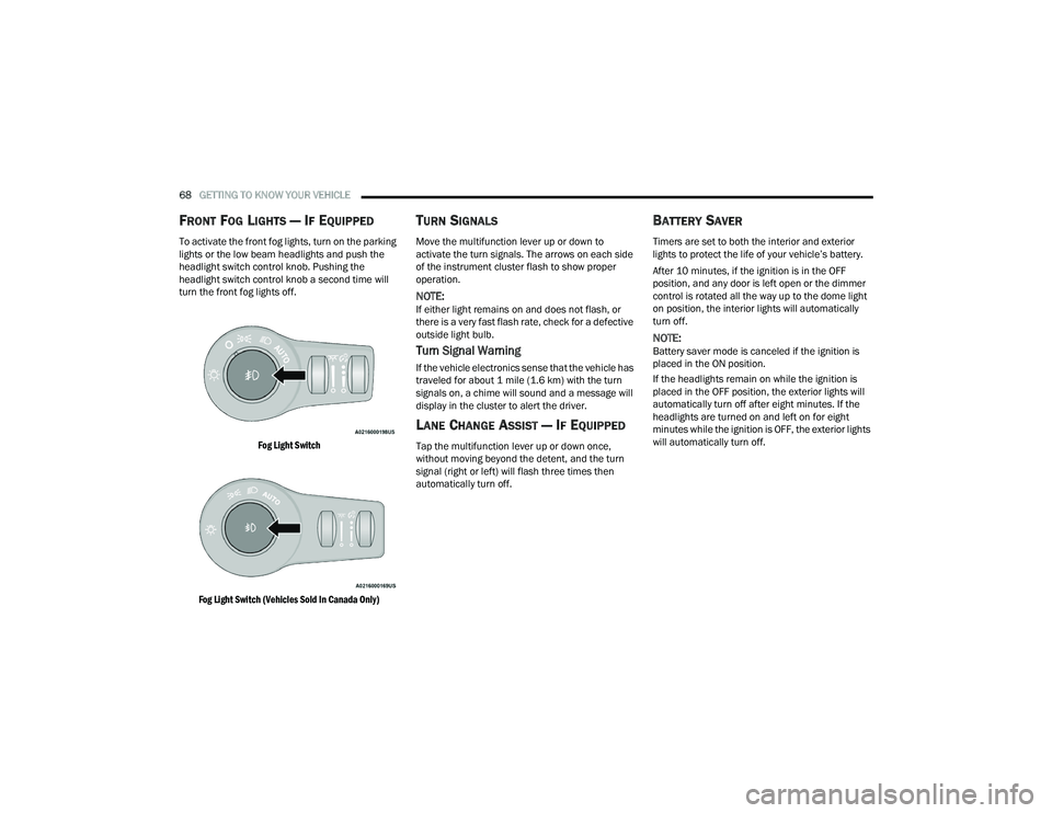
To activate the front fog lights, turn on the parking
lights or the low beam headlights and push the
headlight switch control knob. Pushing the
headlight switch control knob a second time will
turn the front fog lights off.
Fog Light Switch
Fog Light Switch (Vehicles Sold In Canada Only)
TURN SIGNALS
Move the multifunction lever up or down to
activate the turn signals. The arrows on each side
of the instrument cluster flash to show proper
operation.
NOTE:If either light remains on and does not flash, or
there is a very fast flash rate, check for a defective
outside light bulb.
Turn Signal Warning
If the vehicle electronics sense that the vehicle has
traveled for about 1 mile (1.6 km) with the turn signals on, a chime will sound and a message will
display in the cluster to alert the driver.
LANE CHANGE ASSIST — IF EQUIPPED
Tap the multifunction lever up or down once,
without moving beyond the detent, and the turn
signal (right or left) will flash three times then
automatically turn off.
BATTERY SAVER
Timers are set to both the interior and exterior
lights to protect the life of your vehicle’s battery.
After 10 minutes, if the ignition is in the OFF
position, and any door is left open or the dimmer
control is rotated all the way up to the dome light
on position, the interior lights will automatically
turn off.
NOTE:Battery saver mode is canceled if the ignition is
placed in the ON position.
If the headlights remain on while the ignition is
placed in the OFF position, the exterior lights will
automatically turn off after eight minutes. If the
headlights are turned on and left on for eight
minutes while the ignition is OFF, the exterior lights
will automatically turn off.
22_RUP_OM_EN_USC_t.book Page 68
Page 100 of 384
98GETTING TO KNOW YOUR VEHICLE
Using the above ways to open or close the liftgate:
When the liftgate is fully closed, the liftgate will
open
When the liftgate is fully open, the liftgate will
close
When the liftgate is moving, the liftgate will
reverse
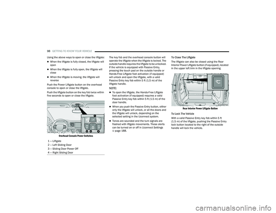
Push the Power Liftgate button on the overhead
console to open or close the liftgate.
Push the liftgate button on the key fob twice within
five seconds to open or close the liftgate.
Overhead Console Power Switches
The key fob and the overhead console button will
operate the liftgate when the liftgate is locked. The
outside handle requires the liftgate to be unlocked.
If the vehicle is equipped with Passive Entry,
pressing the touch pad on the outside handle or
Hands-Free Liftgate foot activation (if equipped)
will unlock and open the liftgate, with a valid
Passive Entry key fob within 5 ft (1.5 m) of the
liftgate handle.
NOTE:
To open the liftgate, the Hands-Free Liftgate
foot activation (if equipped) requires a valid
Passive Entry key fob within 5 ft (1.5 m) of the
door handle.
When you push the Passive Entry button, either
only the liftgate will unlock, or all the doors and
the liftgate will unlock, depending on the
selected setting in the Uconnect system.
Tones are sounded and the turn signals are
flashed with liftgate movements. These alerts
can be turned on or off in Uconnect Settings
Ú page 188. To Close The Liftgate
The liftgate can also be closed using the Rear
Interior Power Liftgate button (if equipped), located
in the upper left trim in the liftgate opening.
Rear Interior Power Liftgate Button
To Lock The Vehicle
With a valid Passive Entry key fob within 5 ft
(1.5 m) of the liftgate, pushing the Passive Entry
lock button located to the right of the outside
handle will lock the vehicle.
1 — Liftgate
2 — Left Sliding Door
3 — Sliding Door Power Off
4 — Right Sliding Door
22_RUP_OM_EN_USC_t.book Page 98
Page 123 of 384
GETTING TO KNOW YOUR INSTRUMENT PANEL121
TRIP COMPUTER
The Trip Computer is located in the instrument
cluster display. Push and release the up or
down arrow button until “Trip Info” is
highlighted in the instrument cluster display.
Navigate between Trip A or Trip B by using the
right and left arrow buttons.
For each trip the following information will be
displayed:
Trip A
Shows the total distance traveled for Trip A
since the last reset.
Shows the Average MPG for Trip A since the last
reset.
Shows the elapsed time traveled for Trip A since
the last reset. Elapsed time will increment when
the ignition switch is in the ON or START position.
Trip B
Shows the total distance traveled for Trip B
since the last reset.
Shows the Average MPG for Trip B since the last
reset.
Shows the elapsed time traveled for Trip B since
the last reset. Elapsed time will increment when
the ignition switch is in the ON or START position.
To Reset A Trip Function
Push and hold the OK button to reset the currently
displayed trip.
WARNING LIGHTS AND MESSAGES
The warning/indicator lights will illuminate in the
instrument panel together with a dedicated
message and/or acoustic signal when applicable.
These indications are indicative and precautionary
and as such must not be considered as exhaustive
and/or alternative to the information contained in
the Owner’s Manual, which you are advised to read
carefully in all cases. Always refer to the
information in this chapter in the event of a failure
indication. All active telltales will display first if
applicable. The system check menu may appear
different based upon equipment options and
current vehicle status. Some telltales are optional
and may not appear.
RED WARNING LIGHTS
Air Bag Warning Light
This warning light will illuminate to
indicate a fault with the air bag, and will
turn on for four to eight seconds as a bulb
check when the ignition is placed in the
ON/RUN or ACC/ON/RUN position. This light will
illuminate with a single chime when a fault with the
air bag has been detected, it will stay on until the
fault is cleared. If the light is either not on during
startup, stays on, or turns on while driving, have
the system inspected at an authorized dealer as
soon as possible.
Battery Charge Warning Light
This warning light will illuminate when
the battery is not charging properly. If it
stays on while the engine is running,
there may be a malfunction with the
charging system. Contact an authorized dealer as
soon as possible.
This indicates a possible problem with the
electrical system or a related component.
3
22_RUP_OM_EN_USC_t.book Page 121
Page 130 of 384

128GETTING TO KNOW YOUR INSTRUMENT PANEL
KeySense Indicator Light —
If Equipped
The KeySense indicator is illuminated
when a KeySense key is detected upon
startup of the vehicle. The indicator will
remain lit for the entire key cycle as a
reminder that the KeySense key is in use. While
the KeySense key is in use, the vehicle will respond
to settings associated with the KeySense profile
Ú page 14.
LaneSense Indicator Light — If Equipped
The LaneSense indicator light illuminates
solid green when both lane markings
have been detected and the system is
“armed” and ready to provide visual and
torque warnings if an unintentional lane departure
occurs Ú page 166.
Parking/Headlights On Indicator Light
This indicator light will illuminate when
the parking lights or headlights are
turned on.
Stop/Start Active Indicator Light —
If Equipped
This indicator light will illuminate when
the Stop/Start function is in “Autostop”
mode Úpage 143.
Turn Signal Indicator Lights
When the left or right turn signal is
activated, the turn signal indicator will
flash independently and the
corresponding exterior turn signal lamps
will flash. Turn signals can be activated when the
multifunction lever is moved down (left) or
up (right).
NOTE:
A continuous chime will sound if the vehicle is
driven more than 1 mile (1.6 km) with either
turn signal on.
Check for an inoperative outside light bulb if
either indicator flashes at a rapid rate.
WHITE INDICATOR LIGHTS
Adaptive Cruise Control (ACC) Ready
Light — If Equipped
This indicator light will illuminate when
the vehicle equipped with ACC has been
turned on but not set Ú page 147.
Cruise Control Ready Indicator Light
This indicator light will illuminate when
the cruise control is ready, but not set
Úpage 146.
LaneSense Indicator Light — If Equipped
When the LaneSense system is ON, but
not armed, the LaneSense indicator light
illuminates solid white. This occurs when
only left, right, or neither lane line has
been detected. If a single lane line is detected, the
system is ready to provide only visual warnings if
an unintentional lane departure occurs on the
detected lane line Ú page 166.
Speed Warning Indicator Light
The white indicator will illuminate along
with a pop-up message (Speed Warning
Set to XX followed by unit), once the
feature is enabled. When the set speed is
exceeded, a continuous chime (up to 10 seconds
or until the speed is no longer exceeded) will sound
along with a Speed Warning Exceeded pop-up
message and the indicator light will turn yellow and
flash.
NOTE:The number “31” is only an example of a speed
that can be selected.
Set Speed Display
The Set Speed Display indicator light
indicates the set speed for the Cruise
Control and Adaptive Cruise Control
(ACC) settings.
22_RUP_OM_EN_USC_t.book Page 128
Page 155 of 384
STARTING AND OPERATING153
NOTE:The “BRAKE!” screen in the instrument cluster
display is a warning for the driver to take action
and does not necessarily mean that the Forward
Collision Warning system is applying the brakes
autonomously.
Overtake Aid
When driving with Adaptive Cruise Control (ACC)
engaged and following a vehicle, the system will
provide an additional acceleration up to the ACC
set speed to assist in passing the vehicle. This
additional acceleration is triggered when the driver
utilizes the left turn signal and will only be active
when passing on the left hand side.
ACC Operation At Stop
In the event that the ACC system brings your
vehicle to a standstill while following the vehicle in
front, your vehicle will resume motion, without the
need for any driver action, if the vehicle in front
starts moving within two seconds.
If the vehicle in front does not start moving within
two seconds of your vehicle coming to a standstill,
the driver will either have to push the RES (resume)
button, or apply the accelerator pedal to reengage
the ACC to the existing set speed.
NOTE:After the ACC system holds your vehicle at a stand -
still for approximately three consecutive minutes,
the parking brake will be activated, and the ACC
system will be canceled.
While the ACC system is holding your vehicle at a
standstill, if the driver seat belt is unbuckled or the
driver door is opened, the parking brake will be
activated, and the ACC system will be canceled.
Display Warnings And Maintenance
“WIPE FRONT RADAR SENSOR” WARNING
The “ACC/AEB Unavailable Wipe Front Radar
Sensor” warning will display and a chime will
sound when conditions temporarily limit system
performance. This most often occurs at times of poor visibility,
such as in snow or heavy rain. The ACC system may
also become temporarily blinded due to
obstructions, such as mud, dirt or ice. In these
cases, the instrument cluster display will show
“ACC/AEB Unavailable Wipe Front Radar Sensor”
and the system will deactivate.
The “ACC/AEB Unavailable Wipe Front Radar
Sensor” message can sometimes be displayed
while driving in highly reflective areas (i.e. ice and
snow, or tunnels with reflective tiles). The ACC
system will recover after the vehicle has left these
areas. Under rare conditions, when the radar is not
tracking any vehicles or objects in its path this
warning may temporarily occur.
NOTE:If the “ACC/AEB Unavailable Wipe Front Radar
Sensor” warning is active, Fixed Speed Cruise
Control is still available.
If weather conditions are not a factor, the driver
should examine the sensor. It may require cleaning
or removal of an obstruction. The sensor is located
in the center of the vehicle behind the lower grille.
WARNING!
When the ACC system is resumed, the driver
must ensure that there are no pedestrians,
vehicles or objects in the path of the vehicle.
Failure to follow these warnings can result in a
collision and death or serious personal injury.
4
22_RUP_OM_EN_USC_t.book Page 153
Page 166 of 384
164STARTING AND OPERATING
NOTE:
When searching for a parking space, use the
turn signal indicator to select which side of the
vehicle you want to perform the parking
maneuver. The ParkSense Active Park Assist
system will automatically search for a parking
space on the passenger's side of the vehicle if
the turn signal is not activated.
The driver needs to make sure that the selected
parking space for the maneuver remains free
and clear of any obstructions (e.g. pedestrians,
bicycles, etc.).
The driver is responsible to ensure that the
selected parking space is suitable for the
maneuver and free/clear of anything that may
be overhanging or protruding into the parking
space (e.g., ladders, tailgates, etc., from
surrounding objects/vehicles).
When searching for a parking space, the driver
should drive as parallel or perpendicular
(depending on the type of maneuver) to other
vehicles as possible.
The feature will only indicate the last detected
parking space (example: if passing multiple
available parking spaces, the system will only
indicate the last detected parking space for the
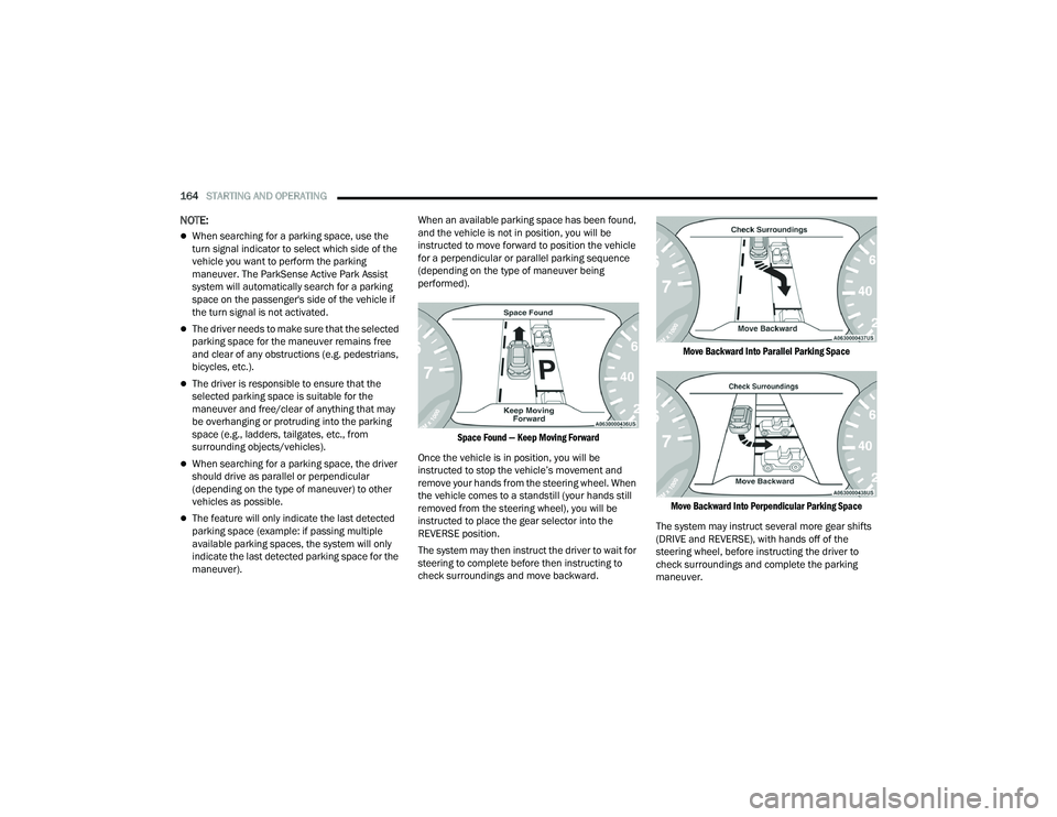
maneuver). When an available parking space has been found,
and the vehicle is not in position, you will be
instructed to move forward to position the vehicle
for a perpendicular or parallel parking sequence
(depending on the type of maneuver being
performed).
Space Found — Keep Moving Forward
Once the vehicle is in position, you will be
instructed to stop the vehicle’s movement and
remove your hands from the steering wheel. When
the vehicle comes to a standstill (your hands still
removed from the steering wheel), you will be
instructed to place the gear selector into the
REVERSE position.
The system may then instruct the driver to wait for
steering to complete before then instructing to
check surroundings and move backward.
Move Backward Into Parallel Parking Space
Move Backward Into Perpendicular Parking Space
The system may instruct several more gear shifts
(DRIVE and REVERSE), with hands off of the
steering wheel, before instructing the driver to
check surroundings and complete the parking
maneuver.
22_RUP_OM_EN_USC_t.book Page 164
Page 168 of 384

166STARTING AND OPERATING
LANESENSE — IF EQUIPPED
LANESENSE OPERATION
The LaneSense system is operational at speeds
above 37 mph (60 km/h) and below 112 mph
(180 km/h). It uses a forward-looking camera to
detect lane markings and measure vehicle
position within the lane boundaries.
When both lane markings are detected and the
driver drifts out of the lane (no turn signal applied),
the LaneSense system provides a haptic warning
in the form of torque applied to the steering wheel,
as well as a visual warning in the instrument
cluster display, to prompt the driver to remain
within the lane boundaries.
The driver may manually override the haptic
warning by applying force to the steering wheel at
any time.
When only a single lane marking is detected and
the driver unintentionally drifts across that lane
marking (no turn signal applied), the LaneSense
system provides a visual warning through the
instrument cluster display to prompt the driver to
remain within the lane. When only a single lane
marking is detected, a haptic or a torque warning
will not be provided.
NOTE:When operating conditions have been met, the
LaneSense system will monitor if the driver’s
hands are on the steering wheel and provide an
audible and visual warning to the driver when the
driver’s hands are not detected on the steering
wheel. The system will cancel if the driver does not
return their hands to the wheel.
TURNING LANESENSE ON OR OFF
The LaneSense button is located on the
switch panel below the Uconnect display.
To turn the LaneSense system on, push the
LaneSense button (LED turns off). A “LaneSense
On” message is shown in the instrument cluster
display.
To turn the LaneSense system off, push the
LaneSense button again (LED turns on).
NOTE:The LaneSense system will retain the last system
state on or off from the last ignition cycle when the
ignition is changed to the ON/RUN position.
LANESENSE WARNING MESSAGE
The LaneSense system will indicate the current
lane drift condition through the instrument cluster
display.
When the LaneSense system is on, the lane lines
are gray when both of the lane boundaries have
not been detected and the LaneSense telltale
is solid white.
System ON (Gray Lines) With White Telltale
22_RUP_OM_EN_USC_t.book Page 166
Page 170 of 384
168STARTING AND OPERATING
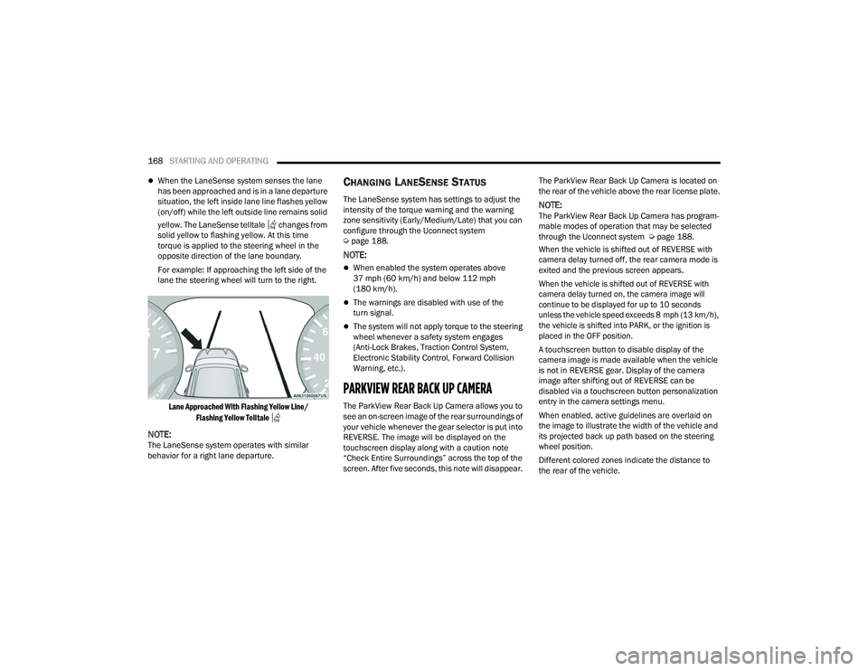
When the LaneSense system senses the lane
has been approached and is in a lane departure
situation, the left inside lane line flashes yellow
(on/off) while the left outside line remains solid
yellow. The LaneSense telltale changes from
solid yellow to flashing yellow. At this time
torque is applied to the steering wheel in the
opposite direction of the lane boundary.
For example: If approaching the left side of the
lane the steering wheel will turn to the right.
Lane Approached With Flashing Yellow Line/ Flashing Yellow Telltale
NOTE:The LaneSense system operates with similar
behavior for a right lane departure.
CHANGING LANESENSE STATUS
The LaneSense system has settings to adjust the
intensity of the torque warning and the warning
zone sensitivity (Early/Medium/Late) that you can
configure through the Uconnect system
Úpage 188.
NOTE:
When enabled the system operates above
37 mph (60 km/h) and below 112 mph
(180 km/h).
The warnings are disabled with use of the
turn signal.
The system will not apply torque to the steering
wheel whenever a safety system engages
(Anti-Lock Brakes, Traction Control System,
Electronic Stability Control, Forward Collision
Warning, etc.).
PARKVIEW REAR BACK UP CAMERA
The ParkView Rear Back Up Camera allows you to
see an on-screen image of the rear surroundings of
your vehicle whenever the gear selector is put into
REVERSE. The image will be displayed on the
touchscreen display along with a caution note
“Check Entire Surroundings” across the top of the
screen. After five seconds, this note will disappear. The ParkView Rear Back Up Camera is located on
the rear of the vehicle above the rear license plate.
NOTE:The ParkView Rear Back Up Camera has program
-
mable modes of operation that may be selected
through the Uconnect system Ú page 188.
When the vehicle is shifted out of REVERSE with
camera delay turned off, the rear camera mode is
exited and the previous screen appears.
When the vehicle is shifted out of REVERSE with
camera delay turned on, the camera image will
continue to be displayed for up to 10 seconds
unless the vehicle speed exceeds 8 mph (13 km/h),
the vehicle is shifted into PARK, or the ignition is
placed in the OFF position.
A touchscreen button to disable display of the
camera image is made available when the vehicle
is not in REVERSE gear. Display of the camera
image after shifting out of REVERSE can be
disabled via a touchscreen button personalization
entry in the camera settings menu.
When enabled, active guidelines are overlaid on
the image to illustrate the width of the vehicle and
its projected back up path based on the steering
wheel position.
Different colored zones indicate the distance to
the rear of the vehicle.
22_RUP_OM_EN_USC_t.book Page 168