stop start CHRYSLER PACIFICA HYBRID 2023 Workshop Manual
[x] Cancel search | Manufacturer: CHRYSLER, Model Year: 2023, Model line: PACIFICA HYBRID, Model: CHRYSLER PACIFICA HYBRID 2023Pages: 328, PDF Size: 16.37 MB
Page 199 of 328
SAFETY197
This indicates there is an internal system fault. Although
the vehicle is still drivable under normal conditions, have
the system checked by an authorized dealer.
Pedestrian Emergency Braking (PEB) —
If Equipped
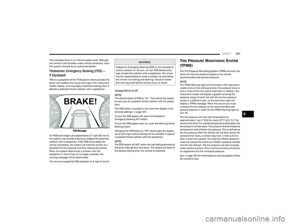
PEB is a subsystem of the FCW system which provides the
driver with audible and visual warnings in the instrument
cluster display, and may apply automatic braking when it
detects a potential frontal collision with a pedestrian.
PEB Message
If a PEB event begins at a speed below 37 mph (60 km/h),
the system may provide braking to mitigate the potential
collision with a pedestrian. If the PEB event stops the
vehicle completely, the system will hold the vehicle at a
standstill for two seconds and then release the brakes.
When the system determines a collision with the
pedestrian in front of you is no longer probable, the
warning message will be deactivated.
The minimum speed for PEB activation is 3 mph (5 km/h). Turning PEB On Or Off
NOTE:The default status of PEB is “On.” This allows the system
to warn you of a possible frontal collision with the pedes
-
trian.
The PEB button is located in the Uconnect display in the
Controls settings
Úpage 157.
To turn the PEB system off, push the Pedestrian
Emergency Braking OFF button.
To turn the PEB system back on, push the Warning Active
Braking button.
Changing the PEB status to “Off” deactivates the system,
so no warning or active braking will be available in case of
a possible frontal collision with the pedestrian.
NOTE:The PEB system will NOT retain the last setting selected by
the driver after ignition shut down. The system will reset to
the default setting when the vehicle is restarted.
TIRE PRESSURE MONITORING SYSTEM
(TPMS)
The Tire Pressure Monitoring System (TPMS) will warn the
driver of a low tire pressure based on the vehicle
recommended cold placard pressure.
NOTE:The TPMS Warning Light will illuminate in the instrument
cluster and a chime will sound when tire pressure is low in
one or more of the four active road tires. In addition, the
instrument cluster will display a graphic showing the
pressure values of each tire with the low tire pressure
values in a different color, or the Uconnect radio will
display a TPMS message. When this occurs you must
increase the tire pressure to the recommended cold
placard pressure in order for the TPMS Warning Light to
turn off.
The tire pressure will vary with temperature by
approximately 1 psi (7 kPa) for every 12°F (6.5°C). This
means that when the outside temperature decreases, the
tire pressure will decrease. Tire pressure should always be
set based on cold inflation tire pressure. This is defined as
the tire pressure after the vehicle has not been driven for
at least three hours, or driven less than 1 mile (1.6 km)
after a three hour period. The cold tire inflation pressure
must not exceed the maximum inflation pressure molded
into the tire sidewall. The tire pressure will also increase
as the vehicle is driven. This is normal and there should be
no adjustment for this increased pressure.
See
Úpage 291 for information on how to properly inflate
the vehicle’s tires.
WARNING!
Pedestrian Emergency Braking (PEB) is not intended to
avoid a collision on its own, nor can PEB detect every
type of potential collision with a pedestrian. The driver
has the responsibility to avoid a collision by controlling
the vehicle via braking and steering. Failure to follow
this warning could lead to serious injury or death.
6
23_RUP_OM_EN_USC_t.book Page 197
Page 220 of 328
218SAFETY
(Continued)
Enhanced Accident Response System
In the event of an impact, if the communication network
remains intact, and the power remains intact, depending
on the nature of the event, the Occupant Restraint
Controller (ORC) will determine whether to have the
Enhanced Accident Response System perform the
following functions:
Cut off fuel to the engine (if equipped).
Cut off battery power to the electric motor (if equipped).
Flash hazard lights as long as the battery has power.
Turn on the interior lights, which remain on as long as
the battery has power or for 15 minutes from the inter -
vention of the Enhanced Accident Response System.
Unlock the power door locks.
Your vehicle may also be designed to perform any of these
other functions in response to the Enhanced Accident
Response System:
Turn off the Fuel Filter Heater, Turn off the HVAC Blower
Motor, Close the HVAC Circulation Door
Cut off battery power to the:
Engine
Electric Motor (if equipped)
Electric power steering
Brake booster
Electric park brake
Automatic transmission gear selector
Horn
Front wiper
Headlight washer pump (if equipped)
NOTE:After an accident, remember to cycle the ignition to the
STOP (OFF/LOCK) position and remove the key from the
ignition switch to avoid draining the battery. Carefully
check the vehicle for fuel leaks in the engine compartment
and on the ground near the engine compartment and fuel
tank before resetting the system and starting the engine.
If there are no fuel leaks or damage to the vehicle elec -
trical devices (e.g. headlights) after an accident, reset the
system by following the procedure described below. If you
have any doubt, contact an authorized dealer.
Enhanced Accident Response System
Reset Procedure
If applicable, refer to the “Hybrid Supplement” for
additional information.
In order to reset the Enhanced Accident Response System
functions after an event, the ignition switch must be
changed from ignition START or ON/RUN to ignition OFF.
Carefully check the vehicle for fuel leaks in the engine
compartment and on the ground near the engine
compartment and fuel tank before resetting the system
and starting the engine.
After an accident, if the vehicle will not start after
performing the reset procedure, the vehicle must be
towed to an authorized dealer to be inspected and to have
the Enhanced Accident Response System reset.
Maintaining Your Air Bag System
WARNING!
Modifications to any part of the air bag system could
cause it to fail when you need it. You could be injured
if the air bag system is not there to protect you. Do
not modify the components or wiring, including
adding any kind of badges or stickers to the steering
wheel hub trim cover or the upper passenger side of
the instrument panel. Do not modify the front fascia/
bumper, vehicle body structure, or add aftermarket
side steps or running boards.
23_RUP_OM_EN_USC_t.book Page 218
Page 245 of 328
IN CASE OF EMERGENCY243
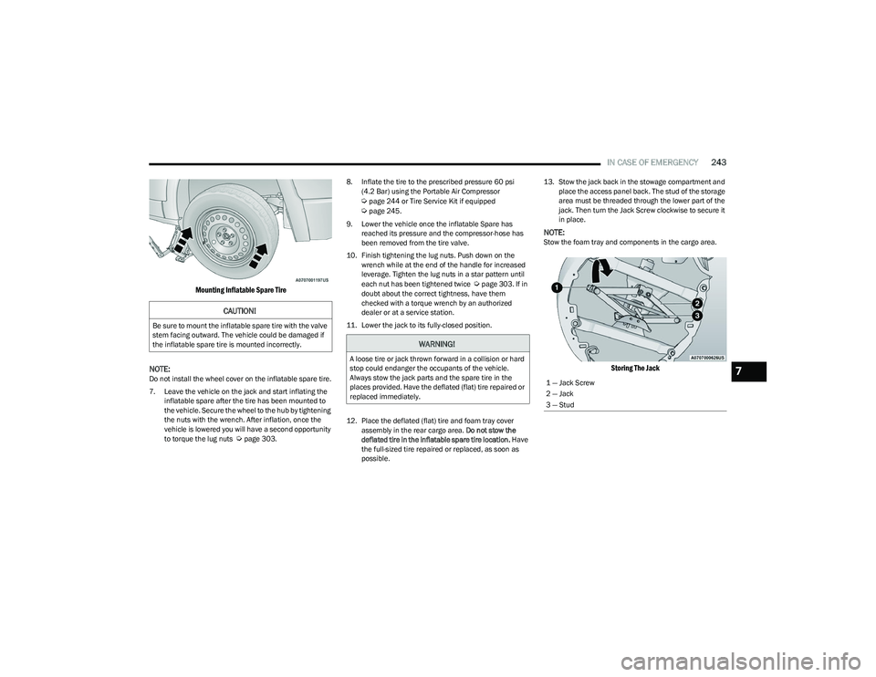
Mounting Inflatable Spare Tire
NOTE:
Do not install the wheel cover on the inflatable spare tire.
7. Leave the vehicle on the jack and start inflating the inflatable spare after the tire has been mounted to
the vehicle. Secure the wheel to the hub by tightening
the nuts with the wrench. After inflation, once the
vehicle is lowered you will have a second opportunity
to torque the lug nuts
Úpage 303. 8. Inflate the tire to the prescribed pressure 60 psi
(4.2 Bar) using the Portable Air Compressor
Úpage 244 or Tire Service Kit if equipped Úpage 245.
9. Lower the vehicle once the inflatable Spare has reached its pressure and the compressor-hose has
been removed from the tire valve.
10. Finish tightening the lug nuts. Push down on the wrench while at the end of the handle for increased
leverage. Tighten the lug nuts in a star pattern until
each nut has been tightened twice
Úpage 303. If in
doubt about the correct tightness, have them
checked with a torque wrench by an authorized
dealer or at a service station.
11. Lower the jack to its fully-closed position.
12. Place the deflated (flat) tire and foam tray cover assembly in the rear cargo area. Do not stow the
deflated tire in the inflatable spare tire location. Have
the full-sized tire repaired or replaced, as soon as
possible. 13. Stow the jack back in the stowage compartment and
place the access panel back. The stud of the storage
area must be threaded through the lower part of the
jack. Then turn the Jack Screw clockwise to secure it
in place.
NOTE:Stow the foam tray and components in the cargo area.
Storing The Jack
CAUTION!
Be sure to mount the inflatable spare tire with the valve
stem facing outward. The vehicle could be damaged if
the inflatable spare tire is mounted incorrectly.
WARNING!
A loose tire or jack thrown forward in a collision or hard
stop could endanger the occupants of the vehicle.
Always stow the jack parts and the spare tire in the
places provided. Have the deflated (flat) tire repaired or
replaced immediately.
1 — Jack Screw
2 — Jack
3 — Stud7
23_RUP_OM_EN_USC_t.book Page 243
Page 250 of 328
248IN CASE OF EMERGENCY
Sealing A Tire With Tire Service Kit
Whenever You Stop To Use Tire Service Kit:
1. Pull over to a safe location and turn on the vehicle’s
Hazard Warning Flashers.
2. Verify that the valve stem (on the wheel with the deflated tire) is in a position that is near to the
ground. This will allow the Tire Service Kit Hose to
reach the valve stem and keep the Tire Service Kit flat
on the ground. This will provide the best positioning of
the kit when injecting the sealant into the deflated
tire and running the air pump. Move the vehicle as
necessary to place the valve stem in this position
before proceeding. 3. Place the gear selector in PARK, then push and
release the ENGINE START/STOP button to set the
ignition switch to the OFF position.
4. Apply the parking brake.
Setting Up To Use Tire Service Kit:
1. Uncoil the Sealant Hose and then remove the cap from the fitting at the end of the hose.
2. Place the Tire Service Kit flat on the
ground next to the deflated tire.
3. Remove the cap from the valve stem and then screw the fitting at the end of the Sealant Hose onto the
valve stem.
4. Uncoil the Power Plug and insert the
plug into the vehicle’s 12 Volt power
outlet.
NOTE:Do not remove foreign objects (e.g., screws or nails) from
the tire.
Injecting Tire Service Kit Sealant Into The Deflated Tire:
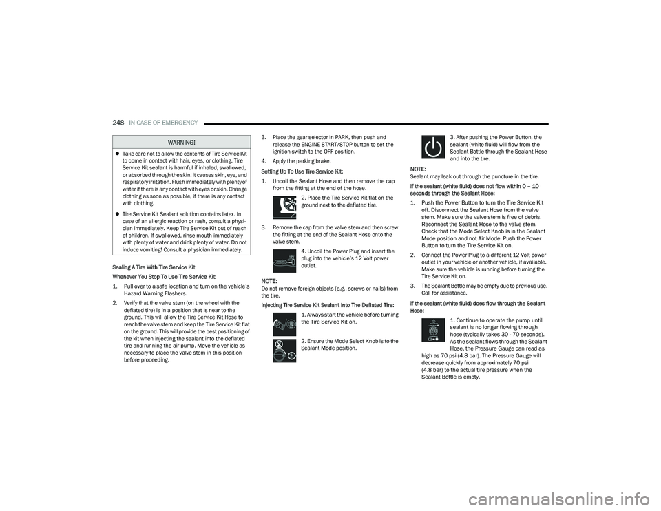
1. Always start the vehicle before turning
the Tire Service Kit on.
2. Ensure the Mode Select Knob is to the
Sealant Mode position. 3. After pushing the Power Button, the
sealant (white fluid) will flow from the
Sealant Bottle through the Sealant Hose
and into the tire.
NOTE:Sealant may leak out through the puncture in the tire.
If the sealant (white fluid) does not flow within 0 – 10
seconds through the Sealant Hose:
1. Push the Power Button to turn the Tire Service Kit
off. Disconnect the Sealant Hose from the valve
stem. Make sure the valve stem is free of debris.
Reconnect the Sealant Hose to the valve stem.
Check that the Mode Select Knob is in the Sealant
Mode position and not Air Mode. Push the Power
Button to turn the Tire Service Kit on.
2. Connect the Power Plug to a different 12 Volt power outlet in your vehicle or another vehicle, if available.
Make sure the vehicle is running before turning the
Tire Service Kit on.
3. The Sealant Bottle may be empty due to previous use. Call for assistance.
If the sealant (white fluid) does flow through the Sealant
Hose:
1. Continue to operate the pump until
sealant is no longer flowing through
hose (typically takes 30 - 70 seconds).
As the sealant flows through the Sealant
Hose, the Pressure Gauge can read as
high as 70 psi (4.8 bar). The Pressure Gauge will
decrease quickly from approximately 70 psi
(4.8 bar) to the actual tire pressure when the
Sealant Bottle is empty.
Take care not to allow the contents of Tire Service Kit
to come in contact with hair, eyes, or clothing. Tire
Service Kit sealant is harmful if inhaled, swallowed,
or absorbed through the skin. It causes skin, eye, and
respiratory irritation. Flush immediately with plenty of
water if there is any contact with eyes or skin. Change
clothing as soon as possible, if there is any contact
with clothing.
Tire Service Kit Sealant solution contains latex. In
case of an allergic reaction or rash, consult a physi -
cian immediately. Keep Tire Service Kit out of reach
of children. If swallowed, rinse mouth immediately
with plenty of water and drink plenty of water. Do not
induce vomiting! Consult a physician immediately.
WARNING!
23_RUP_OM_EN_USC_t.book Page 248
Page 273 of 328
SERVICING AND MAINTENANCE271
Under normal operating conditions, the catalytic converter
will not require maintenance. However, it is important to
keep the engine properly tuned to ensure proper catalyst
operation and prevent possible catalyst damage.
NOTE:Intentional tampering with emissions control systems can
result in civil penalties being assessed against you.
In unusual situations involving grossly malfunctioning
engine operation, a scorching odor may suggest severe
and abnormal catalyst overheating. If this occurs, stop the
vehicle, turn off the engine and allow it to cool. Service,
including a tune-up to the manufacturer specifications,
should be obtained immediately.
To minimize the possibility of catalytic converter damage:
Do not interrupt the ignition when the transmission is
in gear and the vehicle is in motion.
Do not try to start the vehicle by pushing or towing the
vehicle.
Do not idle the engine with any ignition components
disconnected or removed, such as when diagnostic
testing, or for prolonged periods during very rough idle
or malfunctioning operating conditions.
COOLING SYSTEM
Engine Coolant Checks
Check the engine coolant (antifreeze) protection every
12 months (before the onset of freezing weather, where
applicable). If the engine coolant is dirty, the system
should be drained, flushed, and refilled with fresh Organic
Additive Technology (OAT) coolant (conforming to
MS.90032) by an authorized dealer. Check the front of the
A/C condenser for any accumulation of bugs, leaves, etc.
If dirty, clean by gently spraying water from a garden hose
vertically down the face of the condenser.
WARNING!
Exhaust gases can injure or kill. They contain carbon
monoxide (CO), which is colorless and odorless.
Breathing it can make you unconscious and can
eventually poison you
Úpage 233.
A hot exhaust system can start a fire if you park over
materials that can burn, such as grass or leaves, and
those items can come into contact with your exhaust
system. Do not park or operate your vehicle in areas
where your exhaust system can contact anything that
can burn.
CAUTION!
The catalytic converter requires the use of unleaded
fuel only. Leaded gasoline will destroy the effective -
ness of the catalyst as an emissions control device
and may seriously reduce engine performance and
cause serious damage to the engine.
Damage to the catalytic converter can result if your
vehicle is not kept in proper operating condition. In
the event of engine malfunction, particularly
involving engine misfire or other apparent loss of
performance, have your vehicle serviced promptly.
Continued operation of your vehicle with a severe
malfunction could cause the converter to overheat,
resulting in possible damage to the converter and
vehicle.
WARNING!
You or others can be badly burned by hot engine
coolant (antifreeze) or steam from your radiator. If
you see or hear steam coming from under the hood,
do not open the hood until the radiator has had time
to cool. Never open a cooling system pressure cap
when the radiator or coolant bottle is hot.
Keep hands, tools, clothing, and jewelry away from
the radiator cooling fan when the hood is raised. The
fan starts automatically and may start at any time,
whether the engine is running or not.
When working near the radiator cooling fan, discon -
nect the fan motor lead or turn the ignition to the OFF
mode. The fan is temperature controlled and can
start at any time the ignition is in the ON mode.
8
23_RUP_OM_EN_USC_t.book Page 271
Page 301 of 328
SERVICING AND MAINTENANCE299
significantly from the norm due to
variations in driving habits, service
practices, and differences in road
characteristics and climate.
TRACTION GRADES
The Traction grades, from highest to
lowest, are AA, A, B, and C. These grades
represent the tire's ability to stop on wet
pavement, as measured under
controlled conditions on specified
government test surfaces of asphalt and
concrete. A tire marked C may have poor
traction performance.
TEMPERATURE GRADES
The Temperature grades are A (the
highest), B, and C, representing the tire's
resistance to the generation of heat and
its ability to dissipate heat, when tested
under controlled conditions on a
specified indoor laboratory test wheel.
Sustained high temperature can cause
the material of the tire to degenerate
and reduce tire life, and excessive
temperature can lead to sudden tire
failure. The grade C corresponds to a
level of performance, which all
passenger vehicle tires must meet
under the Federal Motor Vehicle Safety
Standard No. 109. Grades B and A
represent higher levels of performance
on the laboratory test wheel, than the
minimum required by law.
STORING THE VEHICLE
If you are storing your vehicle for more than three weeks,
we recommend that you take the following steps to
minimize the drain on your vehicle's battery:
Disconnect the negative cable from battery.
Any time you store your vehicle or keep it out of service
(i.e., vacation) for two weeks or more, run the air condi -
tioning system at idle for about five minutes in the
fresh air and high blower setting. This will ensure
adequate system lubrication to minimize the possibility
of compressor damage when the system is started
again.
WARNING!
The traction grade assigned to this tire is based on
straight-ahead braking traction tests, and does not
include acceleration, cornering, hydroplaning, or peak
traction characteristics.
WARNING!
The temperature grade for this tire is established for a
tire that is properly inflated and not overloaded.
Excessive speed, underinflation, or excessive loading,
either separately or in combination, can cause heat
buildup and possible tire failure.
8
23_RUP_OM_EN_USC_t.book Page 299
Page 319 of 328
317
K
Key Fob ............................................................................12 Arm The System .........................................................19
Disarm The Alarm ...................................................... 19
Programming Additional Key Fobs ...........................14
Key Fob Battery Service (Remote Keyless Entry) .........13
Key Fob Programming (Remote Keyless Entry) ............ 14
Keyless Enter 'n Go™ ...................................................... 21 Passive Entry .............................................................. 21
Keys .................................................................................12
Keysense .........................................................................98
LLane Change And Turn Signals ...................................... 54
Lane Change Assist .................................................54, 57
LaneSense.................................................................... 140
Lap/Shoulder Belts ...................................................... 202
Latches ......................................................................... 235 Hood ...........................................................................82
Lead Free Gasoline ...................................................... 304
Leaks, Fluid .................................................................. 235
Life Of Tires .................................................................. 293
Liftgate .............................................................................83 Hands-Free .................................................................84
Power ..........................................................................83
Light Bulbs ........................................................... 235
, 282 Lights .............................................................................235
Air Bag ................................................... 102
, 209, 233
Anti Lock Brake System ..........................................105
Automatic Emergency Braking OFF ........................ 107 Battery Saver ............................................................. 57
Brake Assist Warning .............................................. 190Brake Warning ......................................................... 103
Bulb Replacement...................................................282
Cruise ............................................................. 107
, 108
Daytime Running ....................................................... 54
Dimmer Switch, Headlight ........................................ 54
Electric Power Steering Fault..................................103
Electronic Park Brake.............................................. 105 Electronic Stability Control Active...........................105
Electronic Throttle Control ...................................... 104Engine Temperature Warning................................. 104
Exterior ........................................................... 235
, 282
Fog.....................................................................57, 108
Headlights ........................................................... 54, 56
High Beam ............................................................... 109
High Beam/Low Beam Select .................................. 54
Hood Open ............................................................... 104
Instrument Cluster .................................................... 54
Intensity Control ........................................................ 58
Interior........................................................................ 58
KeySense ................................................................. 108
LaneSense ..................................................... 105
, 108 Liftgate Open ........................................................... 104
Lights On Reminder ........................................... 54
, 57
Low Fuel................................................................... 105
Low Washer Fluid .................................................... 106
Malfunction Indicator (Check Engine) ................... 106 Oil Pressure ............................................................. 104
Oil Temperature ...................................................... 104
Park .......................................................................... 108
Passing ............................................................... 54
, 56
Reading...................................................................... 58
Seat Belt Reminder ................................................. 104 Security Alarm ......................................................... 105
Service ..................................................................... 282Service Automatic Emergency Braking.................. 106
Service AWD ............................................................ 106
Service LaneSense ................................................. 106Service Stop Start System ...................................... 106
Side Marker ............................................................. 282
SmartBeams.............................................................. 56
Stop Start Active...................................................... 108
Tire Pressure Monitoring (TPMS) ........................... 106Traction Control ....................................................... 190Transmission Temperature .................................... 104
Turn Signals................................... 54
, 108, 235, 282
Load Floor, Cargo ........................................................... 86
Load Shed Battery Saver Mode................................... 101
11
23_RUP_OM_EN_USC_t.book Page 317