engine CHRYSLER VOYAGER 2001 Service Manual
[x] Cancel search | Manufacturer: CHRYSLER, Model Year: 2001, Model line: VOYAGER, Model: CHRYSLER VOYAGER 2001Pages: 4284, PDF Size: 83.53 MB
Page 4250 of 4284

Symptom:
*BRAKE SHIFT INTERLOCK OUTPUT OPEN
POSSIBLE CAUSES
INTERMITTENT WIRING AND CONNECTORS
BRAKE SHIFT INTERLOCK CONTROL CIRCUIT OPEN
BRAKE SHIFT INTERLOCK FEED CIRCUIT OPEN
BRAKE SHIFT INTERLOCK SOLENOID
FRONT CONTROL MODULE
TEST ACTION APPLICABILITY
1 Ignition on, engine not running.
With the DRBIIIt, record and erase DTC's.
Turn the ignition off to the lock position.
Turn the ignition on.
With the DRBIIIt, read DTCs.
Does the DRBIIItdisplay BRAKE SHIFT INTERLOCK OUTPUT OPEN?All
Ye s®Go To 2
No®Go To 8
2 Turn the ignition off to the lock position.
Disconnect the Brake Shift Interlock harness connector.
Note: Check connectors - Clean/repair as necessary.
Ignition on, engine not running.
Using a 12-volt test light connected to B+, check the Brake Shift Interlock Control
circuit in the Brake Shift Interlock harness connector.
NOTE: The test light must illuminate brightly. Compare the brightness to
that of a direct connection to the battery.
Does the test light illuminate brightly?All
Ye s®Go To 3
No®Go To 6
3 Turn the ignition off to the lock position.
Disconnect the Brake Shift Interlock harness connector.
Note: Check connectors - Clean/repair as necessary.
Ignition on, engine not running.
Using a 12-volt test light connected to ground, check the Brake Shift Interlock Feed
circuit in the Brake Shift Interlock harness connector.
NOTE: The test light must illuminate brightly. Compare the brightness to
that of a direct connection to the battery.
Does the test light illuminate brightly?All
Ye s®Go To 4
No®Go To 5
4 If there are no possible causes remaining, view repair. All
Repair
Replace the Brake Shift Interlock Solenoid in accordance with the
Service Information.
146
TRANSMISSION
Page 4258 of 4284

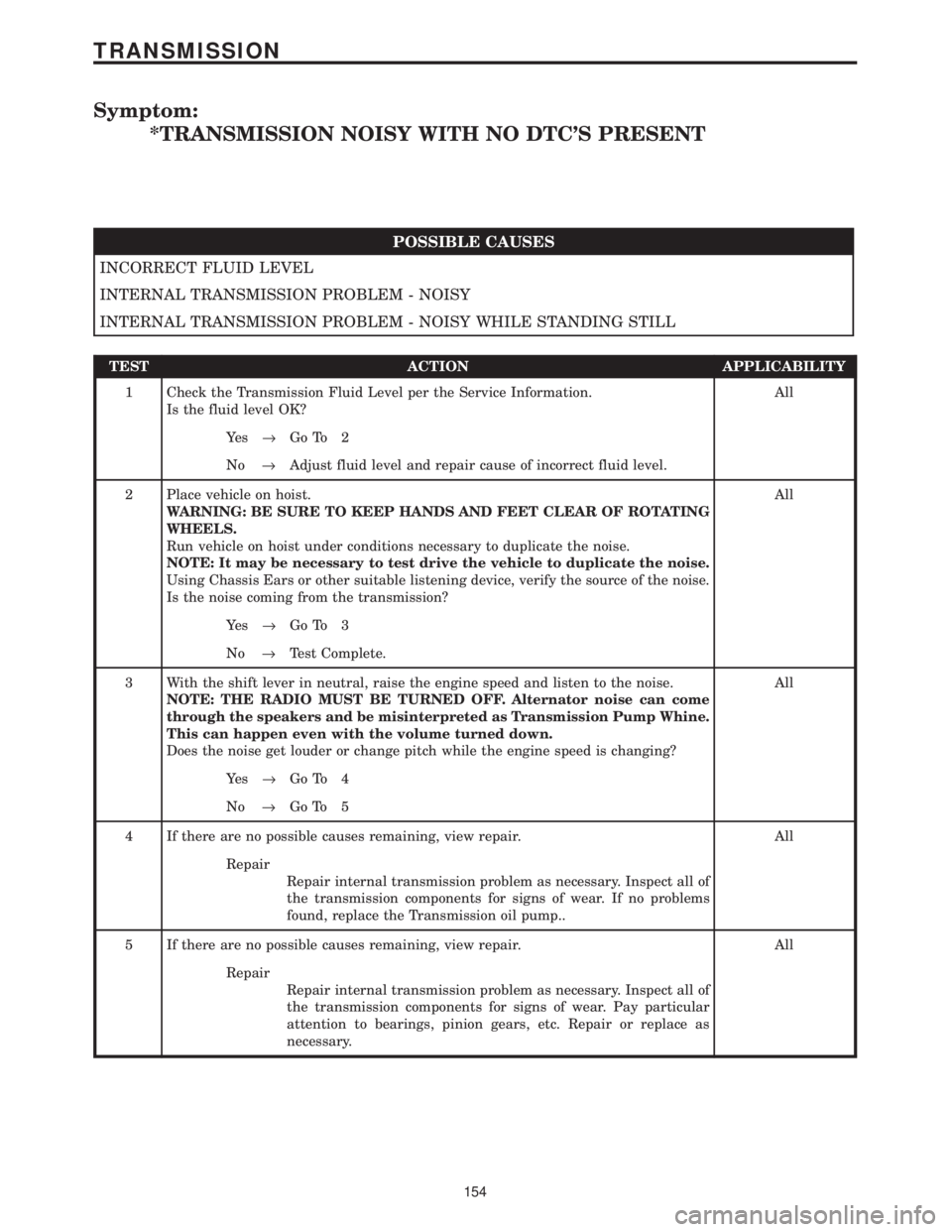
Symptom:
*TRANSMISSION NOISY WITH NO DTC'S PRESENT
POSSIBLE CAUSES
INCORRECT FLUID LEVEL
INTERNAL TRANSMISSION PROBLEM - NOISY
INTERNAL TRANSMISSION PROBLEM - NOISY WHILE STANDING STILL
TEST ACTION APPLICABILITY
1 Check the Transmission Fluid Level per the Service Information.
Is the fluid level OK?All
Ye s®Go To 2
No®Adjust fluid level and repair cause of incorrect fluid level.
2 Place vehicle on hoist.
WARNING: BE SURE TO KEEP HANDS AND FEET CLEAR OF ROTATING
WHEELS.
Run vehicle on hoist under conditions necessary to duplicate the noise.
NOTE: It may be necessary to test drive the vehicle to duplicate the noise.
Using Chassis Ears or other suitable listening device, verify the source of the noise.
Is the noise coming from the transmission?All
Ye s®Go To 3
No®Test Complete.
3 With the shift lever in neutral, raise the engine speed and listen to the noise.
NOTE: THE RADIO MUST BE TURNED OFF. Alternator noise can come
through the speakers and be misinterpreted as Transmission Pump Whine.
This can happen even with the volume turned down.
Does the noise get louder or change pitch while the engine speed is changing?All
Ye s®Go To 4
No®Go To 5
4 If there are no possible causes remaining, view repair. All
Repair
Repair internal transmission problem as necessary. Inspect all of
the transmission components for signs of wear. If no problems
found, replace the Transmission oil pump..
5 If there are no possible causes remaining, view repair. All
Repair
Repair internal transmission problem as necessary. Inspect all of
the transmission components for signs of wear. Pay particular
attention to bearings, pinion gears, etc. Repair or replace as
necessary.
154
TRANSMISSION
Page 4261 of 4284

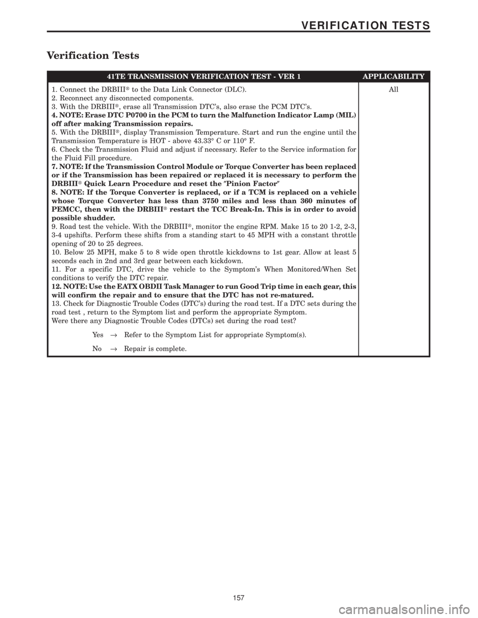
Verification Tests
41TE TRANSMISSION VERIFICATION TEST - VER 1 APPLICABILITY
1. Connect the DRBIIItto the Data Link Connector (DLC).
2. Reconnect any disconnected components.
3. With the DRBIIIt, erase all Transmission DTC's, also erase the PCM DTC's.
4. NOTE: Erase DTC P0700 in the PCM to turn the Malfunction Indicator Lamp (MIL)
off after making Transmission repairs.
5. With the DRBIIIt, display Transmission Temperature. Start and run the engine until the
Transmission Temperature is HOT - above 43.33É C or 110É F.
6. Check the Transmission Fluid and adjust if necessary. Refer to the Service information for
the Fluid Fill procedure.
7. NOTE: If the Transmission Control Module or Torque Converter has been replaced
or if the Transmission has been repaired or replaced it is necessary to perform the
DRBIIItQuick Learn Procedure and reset the(Pinion Factor(
8. NOTE: If the Torque Converter is replaced, or if a TCM is replaced on a vehicle
whose Torque Converter has less than 3750 miles and less than 360 minutes of
PEMCC, then with the DRBIIItrestart the TCC Break-In. This is in order to avoid
possible shudder.
9. Road test the vehicle. With the DRBIIIt, monitor the engine RPM. Make 15 to 20 1-2, 2-3,
3-4 upshifts. Perform these shifts from a standing start to 45 MPH with a constant throttle
opening of 20 to 25 degrees.
10. Below 25 MPH, make 5 to 8 wide open throttle kickdowns to 1st gear. Allow at least 5
seconds each in 2nd and 3rd gear between each kickdown.
11. For a specific DTC, drive the vehicle to the Symptom's When Monitored/When Set
conditions to verify the DTC repair.
12. NOTE: Use the EATX OBDII Task Manager to run Good Trip time in each gear, this
will confirm the repair and to ensure that the DTC has not re-matured.
13. Check for Diagnostic Trouble Codes (DTC's) during the road test. If a DTC sets during the
road test , return to the Symptom list and perform the appropriate Symptom.
Were there any Diagnostic Trouble Codes (DTCs) set during the road test?All
Ye s®Refer to the Symptom List for appropriate Symptom(s).
No®Repair is complete.
157
VERIFICATION TESTS
Page 4262 of 4284

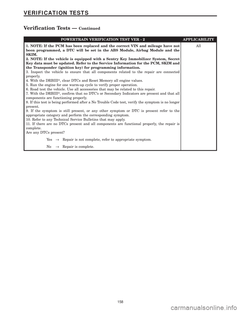
POWERTRAIN VERIFICATION TEST VER - 2 APPLICABILITY
1. NOTE: If the PCM has been replaced and the correct VIN and mileage have not
been programmed, a DTC will be set in the ABS Module, Airbag Module and the
SKIM.
2. NOTE: If the vehicle is equipped with a Sentry Key Immobilizer System, Secret
Key data must be updated. Refer to the Service Information for the PCM, SKIM and
the Transponder (ignition key) for programming information.
3. Inspect the vehicle to ensure that all components related to the repair are connected
properly.
4. With the DRBIIIt, clear DTCs and Reset Memory all engine values.
5. Run the engine for one warm-up cycle to verify proper operation.
6. Road test the vehicle. Use all accessories that may be related to this repair.
7. With the DRBIIIt, confirm that no DTC's or Secondary Indicators are present and that all
components are functioning properly.
8. If this test is being performed after a No Trouble Code test, verify the symptom is no longer
present.
9. If the symptom is still present, or any other symptom or DTC is present refer to the
appropriate category and perform the corresponding symptom.
10. Refer to any Technical Service Bulletins that may apply.
11. If there are no DTCs present and all components are functional properly, the repair is
complete.
Are any DTCs present?All
Ye s®Repair is not complete, refer to appropriate symptom.
No®Repair is complete.
158
VERIFICATION TESTS
Verification Tests ÐContinued
Page 4269 of 4284

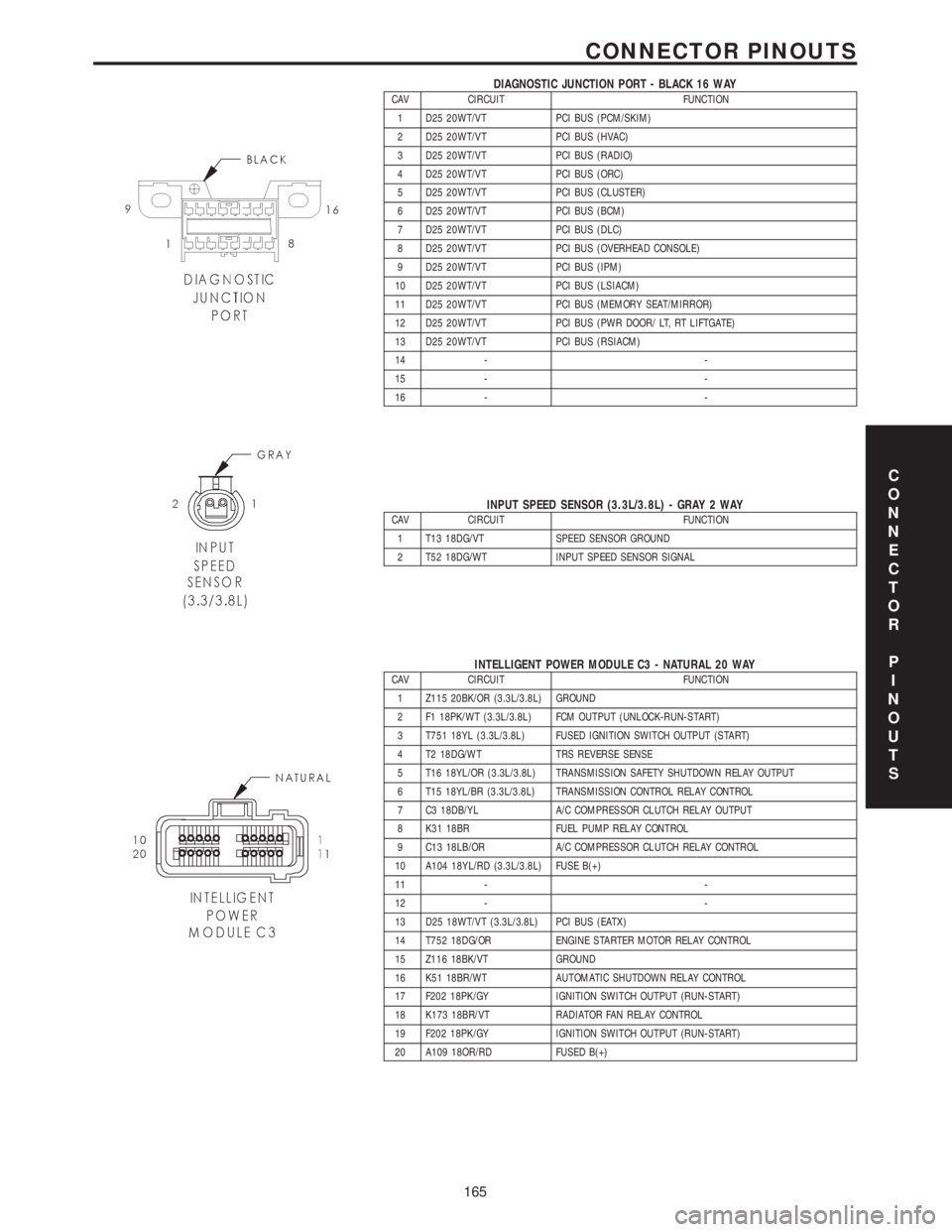
DIAGNOSTIC JUNCTION PORT - BLACK 16 WAYCAV CIRCUIT FUNCTION
1 D25 20WT/VT PCI BUS (PCM/SKIM)
2 D25 20WT/VT PCI BUS (HVAC)
3 D25 20WT/VT PCI BUS (RADIO)
4 D25 20WT/VT PCI BUS (ORC)
5 D25 20WT/VT PCI BUS (CLUSTER)
6 D25 20WT/VT PCI BUS (BCM)
7 D25 20WT/VT PCI BUS (DLC)
8 D25 20WT/VT PCI BUS (OVERHEAD CONSOLE)
9 D25 20WT/VT PCI BUS (IPM)
10 D25 20WT/VT PCI BUS (LSIACM)
11 D25 20WT/VT PCI BUS (MEMORY SEAT/MIRROR)
12 D25 20WT/VT PCI BUS (PWR DOOR/ LT, RT LIFTGATE)
13 D25 20WT/VT PCI BUS (RSIACM)
14 - -
15 - -
16 - -
INPUT SPEED SENSOR (3.3L/3.8L) - GRAY 2 WAYCAV CIRCUIT FUNCTION
1 T13 18DG/VT SPEED SENSOR GROUND
2 T52 18DG/WT INPUT SPEED SENSOR SIGNAL
INTELLIGENT POWER MODULE C3 - NATURAL 20 WAYCAV CIRCUIT FUNCTION
1 Z115 20BK/OR (3.3L/3.8L) GROUND
2 F1 18PK/WT (3.3L/3.8L) FCM OUTPUT (UNLOCK-RUN-START)
3 T751 18YL (3.3L/3.8L) FUSED IGNITION SWITCH OUTPUT (START)
4 T2 18DG/WT TRS REVERSE SENSE
5 T16 18YL/OR (3.3L/3.8L) TRANSMISSION SAFETY SHUTDOWN RELAY OUTPUT
6 T15 18YL/BR (3.3L/3.8L) TRANSMISSION CONTROL RELAY CONTROL
7 C3 18DB/YL A/C COMPRESSOR CLUTCH RELAY OUTPUT
8 K31 18BR FUEL PUMP RELAY CONTROL
9 C13 18LB/OR A/C COMPRESSOR CLUTCH RELAY CONTROL
10 A104 18YL/RD (3.3L/3.8L) FUSE B(+)
11 - -
12 - -
13 D25 18WT/VT (3.3L/3.8L) PCI BUS (EATX)
14 T752 18DG/OR ENGINE STARTER MOTOR RELAY CONTROL
15 Z116 18BK/VT GROUND
16 K51 18BR/WT AUTOMATIC SHUTDOWN RELAY CONTROL
17 F202 18PK/GY IGNITION SWITCH OUTPUT (RUN-START)
18 K173 18BR/VT RADIATOR FAN RELAY CONTROL
19 F202 18PK/GY IGNITION SWITCH OUTPUT (RUN-START)
20 A109 18OR/RD FUSED B(+)
C
O
N
N
E
C
T
O
R
P
I
N
O
U
T
S
165
CONNECTOR PINOUTS
Page 4270 of 4284

INTELLIGENT POWER MODULE C4 - GRAY 10 WAYCAV CIRCUIT FUNCTION
1 Z127 12BK/DG GROUND
2 T750 12YL/GY ENGINE STARTER MOTOR RELAY OUTPUT
3 K342 16BR/WT AUTOMATIC SHUTDOWN RELAY OUTPUT
4 F500 18DG/PK (ANTILOCK
BRAKES)FUSED IGNITION SWITCH RELAY OUTPUT (RUN)
5- -
6 D25 16WT/VT (ANTILOCK
BRAKES)PCI BUS
7 A107 12TN/RD (ANTILOCK
BRAKES)FUSED B(+)
8 A111 12DG/RD (ANTILOCK
BRAKES)FUSED B(+)
9 A701 14BR/RD FUSED B(+)
10 - -
INTELLIGENT POWER MODULE C5 - BLACK 4 WAYCAV CIRCUIT FUNCTION
1 A1 04RD B(+)
2- -
3- -
4- -
INTELLIGENT POWER MODULE C6 - WHITE 10 WAYCAV CIRCUIT FUNCTION
1 A101 12VT/RD FUSED B(+)
2 Z117 16BK/WT GROUND
3 Z118 16BK/YL GROUND
4 A110 12OR/RD (POWER
SEAT)FUSED B(+)
5- -
6- -
7 C7 12DB FUSED FRONT BLOWER MOTOR RELAY OUTPUT
8 F307 16LB/PK (ACCESSO-
RY RELAY POSITION)FUSED ACCESSORY RELAY OUTPUT
8 F307 16LB/PK (BATTERY
POSITION)FUSED B(+)
9 A113 12WT/RD (POWER
SLIDING DOOR)FUSED B(+)
10 - -
C
O
N
N
E
C
T
O
R
P
I
N
O
U
T
S
166
CONNECTOR PINOUTS
Page 4275 of 4284

POWERTRAIN CONTROL MODULE C1 - GRAY/BLACK 40 WAYCAV CIRCUIT FUNCTION
1- -
2 K18 16DB/OR (3.3L/3.8L) IGNITION COIL NO. 3 DRIVER
3 K17 16DB/TN IGNITION COIL NO. 2 DRIVER
4- -
5 V32 18VT/YL SPEED CONTROL ON/OFF SWITCH SENSE
6 K342 16BR/WT AUTOMATIC SHUTDOWN RELAY OUTPUT
7 K13 16BR/LB FUEL INJECTOR NO. 3 DRIVER
8 K20 18BR/GY GENERATOR FIELD DRIVER (+)
9- -
10 Z130 18BK/BR GROUND
11 K19 16DB/DG IGNITION COIL NO. 1 DRIVER
12 G6 16VT/GY ENGINE OIL PRESSURE SWITCH SENSE
13 K11 16BR/YL FUEL INJECTOR NO. 1 DRIVER
14 K58 16BR/VT (3.3L/3.8L) FUEL INJECTOR NO. 6 DRIVER
15 K38 16BR/OR (3.3L/3.8L) FUEL INJECTOR NO. 5 DRIVER
16 K14 16BR/TN FUEL INJECTOR NO. 4 DRIVER
17 K12 16BR/DB FUEL INJECTOR NO. 2 DRIVER
18 K99 18BR/LG OXYGEN SENSOR 1/1 HEATER CONTROL
19 - -
20 F202 18PK/GY FUSED IGNITION SWITCH OUTPUT (RUN-START)
21 - -
22 - -
23 - -
24 - -
25 K42 18DB/YL KNOCK SENSOR SIGNAL
26 K2 18VT/OR ENGINE COOLANT TEMPERATURE SENSOR SIGNAL
27 K902 18BR/DG OXYGEN SENSOR GROUND
28 - -
29 - -
30 K41 18DB/LB OXYGEN SENSOR 1/1 SIGNAL
31 T752 18DG/OR DOUBLE START OVERRIDE
32 K24 18BR/LB CRANKSHAFT POSITION SENSOR SIGNAL
33 K44 18DB/GY CAMSHAFT POSITION SENSOR SIGNAL
34 - -
35 K22 18BR/OR THROTTLE POSITION SENSOR SIGNAL
36 K1 18VT/BR MANIFOLD ABSOLUTE PRESSURE SENSOR SIGNAL
37 K21 18DB/LG INTAKE AIR TEMPERATURE SIGNAL
38 - -
39 - -
40 K35 18DB/VT EGR SOLENOID CONTROL
C
O
N
N
E
C
T
O
R
P
I
N
O
U
T
S
171
CONNECTOR PINOUTS