CHRYSLER VOYAGER 2001 Service Manual
Manufacturer: CHRYSLER, Model Year: 2001, Model line: VOYAGER, Model: CHRYSLER VOYAGER 2001Pages: 4284, PDF Size: 83.53 MB
Page 2061 of 4284
defective they must be replaced. After an airbag
deployment, the tensioner must be replaced.
OPERATION
At the onset of an impact event, each tensioner
uses a pyrotechnic device which is triggered simulta-
neously with the airbags to rapidly retract the seat
belts. With the slack removed, the occupant's forward
motion in an impact will be reduced as will the like-
lihood of contacting interior components. After an
impact that deploys the airbags, the seat belt ten-
sioner assembly must be replaced.
The Occupant Restraint Controller (ORC) monitors
the seat belt tensioner circuit resistance and reports
active and stored Diagnostic Trouble Codes (DTC's) if
any problem is found.
Once a vehicle has been in an accident, the tensioner
must be replaced along with any deployed airbags and
broken or damaged parts. Refer to the proper Body
Diagnostic Procedures manual for diagnosis and testing.
WARNING: WHEN THE FRONT AIRBAG IS
DEPLOYED, THE TENSIONER WILL HAVE
DEPLOYED ALSO AND SHOULD BE REPLACED.
SHOULDER BELT HEIGHT
ADJUSTER
REMOVAL
(1) Remove B or C-pillar trim cover.
(2) Remove screws attaching shoulder belt height
adjuster to pillar.
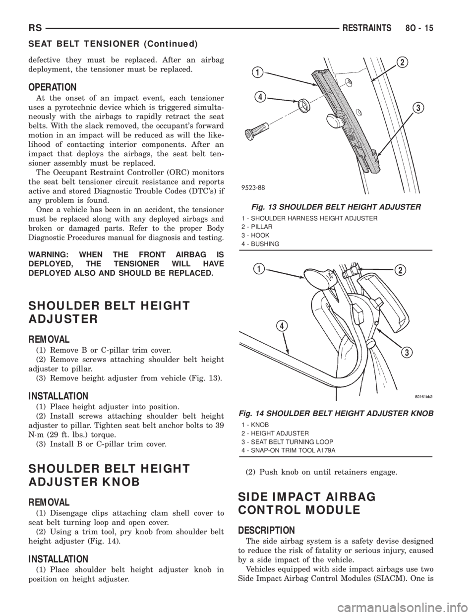
(3) Remove height adjuster from vehicle (Fig. 13).
INSTALLATION
(1) Place height adjuster into position.
(2) Install screws attaching shoulder belt height
adjuster to pillar. Tighten seat belt anchor bolts to 39
N´m (29 ft. lbs.) torque.
(3) Install B or C-pillar trim cover.
SHOULDER BELT HEIGHT
ADJUSTER KNOB
REMOVAL
(1) Disengage clips attaching clam shell cover to
seat belt turning loop and open cover.
(2) Using a trim tool, pry knob from shoulder belt
height adjuster (Fig. 14).
INSTALLATION
(1) Place shoulder belt height adjuster knob in
position on height adjuster.(2) Push knob on until retainers engage.
SIDE IMPACT AIRBAG
CONTROL MODULE
DESCRIPTION
The side airbag system is a safety devise designed
to reduce the risk of fatality or serious injury, caused
by a side impact of the vehicle.
Vehicles equipped with side impact airbags use two
Side Impact Airbag Control Modules (SIACM). One is
Fig. 13 SHOULDER BELT HEIGHT ADJUSTER
1 - SHOULDER HARNESS HEIGHT ADJUSTER
2 - PILLAR
3 - HOOK
4 - BUSHING
Fig. 14 SHOULDER BELT HEIGHT ADJUSTER KNOB
1 - KNOB
2 - HEIGHT ADJUSTER
3 - SEAT BELT TURNING LOOP
4 - SNAP-ON TRIM TOOL A179A
RSRESTRAINTS8O-15
SEAT BELT TENSIONER (Continued)
Page 2062 of 4284
located on each respective side body B-pillar. Each
contains an impact sensor that senses a side impact
occurrence. The SIACM communicates with the ORC
via the PCI bus in order to notify the driver of any
potential side airbag system problem.
OPERATION
The impact sensor provides verification of the
direction and severity of the side impact. The right
side SIACM controls the right seat airbag. The left
side SIACM controls the left seat airbag. In the event
of a side impact the appropriate SIACM will send an
electronic signal to its airbag, deploying the airbag.
The SIACM communicates with the Occupant
Restraint Controller (ORC) via the PCI bus circuit.
The accelerometer pulses are sent to a micropro-
cessor, which contains a decision algorithm. When an
impact is severe enough to require airbag protection,
the SIACM microprocessor sends a signal to deploy
the side airbag that completes the electrical circuits
to the right or left side airbag. The sensor is cali-
brated for the specific vehicle and reacts to the sever-
ity and direction of the impact.
REMOVAL
(1) Disconnect and isolate the battery negative
cable terminal.(2) Remove the lower B-pillar trim from the appro-
priate side of the vehicle. Refer to Body, Interior,
B-Pillar Lower Trim, Removal.
(3) Remove the three SIACM retaining screws and
remove the module from the vehicle.
(4) Disconnect the SIACM electrical connector.
INSTALLATION
(1) Connect the SIACM electrical connector.
(2) Place the module in the slot on their respective
B-pillar. Install the three SIACM retaining screws.
Torque screws to 5.7 - 7.9 N´m (50 - 70 lbs.)
(3) Install the lower B-pillar trim on the appropri-
ate side of the vehicle. Refer to Body, Interior, B-Pil-
lar Lower Trim, Installation.
WARNING: DO NOT CONNECT THE BATTERY NEG-
ATIVE CABLE. REFER TO ELECTRICAL,
RESTRAINTS, DIAGNOSIS AND TESTING - AIRBAG
SYSTEM FIRST.
8O - 16 RESTRAINTSRS
SIDE IMPACT AIRBAG CONTROL MODULE (Continued)
Page 2063 of 4284
SPEED CONTROL
TABLE OF CONTENTS
page page
SPEED CONTROL
DESCRIPTION............................1
OPERATION.............................1
DIAGNOSIS AND TESTING..................3
ROAD TEST............................3
SPECIFICATIONS.........................3
CABLE
DESCRIPTION............................3
OPERATION.............................3
REMOVAL...............................3
INSTALLATION............................4
SERVO
DESCRIPTION............................4OPERATION.............................4
REMOVAL...............................4
INSTALLATION............................4
SWITCH
DESCRIPTION............................5
OPERATION.............................5
REMOVAL...............................5
INSTALLATION............................5
VACUUM RESERVOIR
DESCRIPTION............................6
OPERATION.............................6
REMOVAL...............................6
INSTALLATION............................6
SPEED CONTROL
DESCRIPTION
The speed control system is electronically con-
trolled and vacuum operated. The electronic control
is integrated into the powertrain control module,
located on the driver's side under the speed control
servo. The controls are located on the steering wheel.
The ON, OFF, and SET buttons are located on the
left side of the airbag module. The RESUME,
ACCEL, CANCEL and COAST buttons are located on
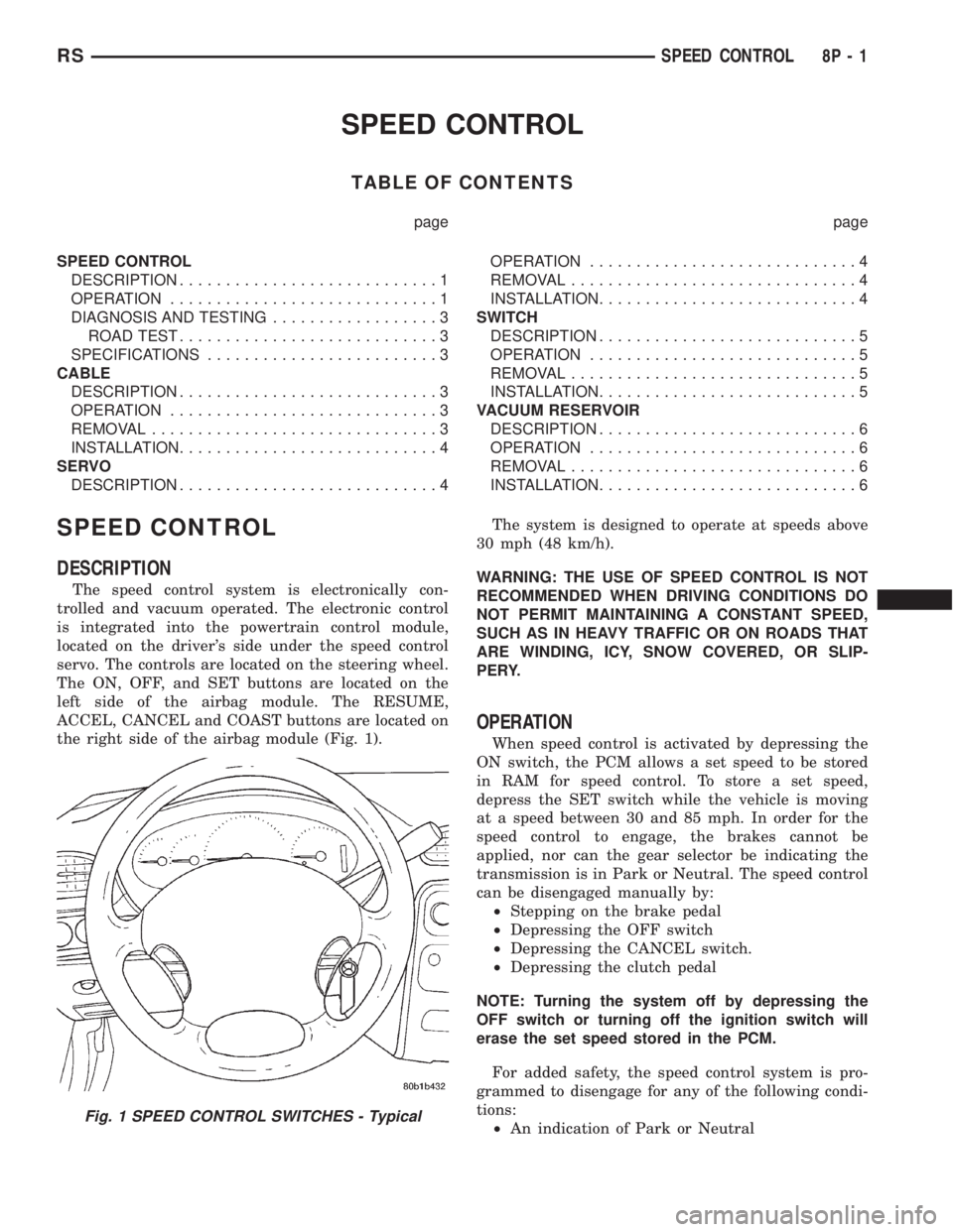
the right side of the airbag module (Fig. 1).The system is designed to operate at speeds above
30 mph (48 km/h).
WARNING: THE USE OF SPEED CONTROL IS NOT
RECOMMENDED WHEN DRIVING CONDITIONS DO
NOT PERMIT MAINTAINING A CONSTANT SPEED,
SUCH AS IN HEAVY TRAFFIC OR ON ROADS THAT
ARE WINDING, ICY, SNOW COVERED, OR SLIP-
PERY.
OPERATION
When speed control is activated by depressing the
ON switch, the PCM allows a set speed to be stored
in RAM for speed control. To store a set speed,
depress the SET switch while the vehicle is moving
at a speed between 30 and 85 mph. In order for the
speed control to engage, the brakes cannot be
applied, nor can the gear selector be indicating the
transmission is in Park or Neutral. The speed control
can be disengaged manually by:
²Stepping on the brake pedal
²Depressing the OFF switch
²Depressing the CANCEL switch.
²Depressing the clutch pedal
NOTE: Turning the system off by depressing the
OFF switch or turning off the ignition switch will
erase the set speed stored in the PCM.
For added safety, the speed control system is pro-
grammed to disengage for any of the following condi-
tions:
²An indication of Park or Neutral
Fig. 1 SPEED CONTROL SWITCHES - Typical
RSSPEED CONTROL8P-1
Page 2064 of 4284
²A rapid increase rpm (indicates that the clutch
has been disengaged)
²Excessive engine rpm (indicates that the trans-
mission may be in a low gear)
²The speed signal increases at a rate of 10 mph
per second (indicates that the co-efficient of friction
between the road surface and tires is extremely low)
²The speed signal decreases at a rate of 10 mph
per second (indicates that the vehicle may have
decelerated at an extremely high rate)
²If the actual speed is not within 20 mph of the
set speed. The previous disengagement conditions are
programmed for added safety.
Once the speed control has been disengaged,
depressing the RESUME switch when speed is
greater than 25 mph allows the vehicle to resume
control to the target speed that was stored in the
PCM.
While the speed control is engaged, the driver can
increase the vehicle speed by depressing the ACCEL
switch. The new target speed is stored in the PCM
when the ACCEL switch is released. The PCM also
has a9tap-up9feature in which target speed
increases by 2 mph for each momentary switch acti-
vation of the ACCEL switch. The PCM also provides
a means to decelerate to a new lower target speed
without disengaging speed control. Depress and hold
the COAST switch until the desired speed is reached,
then release the switch.
The PCM also has a ªTap Downº feature in which
target speed decreases at 1 mph for each momentary
switch activation of the coast switch.
OPERATION - INTERACTIVE SPEED CONTROL
(4 Speed EATX Only)
Interactive means that communication between the
PCM and the TCM is taking place. Interactive speed
control avoids unnecessary shifting for smoother, qui-
eter operation and when downshifts are required,
makes the shifts smoother.
CLIMBING A GRADE
DESCRIPTION
When climbing a grade the interactive speed con-
trol tries to maintain the set speed by increasing the
throttle opening, while inability/delaying downshifts.
OPERATION
If opening the throttle alone cannot maintain the
set speed and the vehicle speed drops more than three
mph below the set speed, the transmission will down-
shift to third gear. If the vehicle continues to lose
speed, by more than 6 mph, the transmission will
downshift again to maintain the set speed. After the
vehicle encounters a less-steep grade, or has crestedthe grade (reduced the load on the powertrain) and
can maintain the set speed at a reduced throttle posi-
tion, the transmission will upshift, as appropriate,
until the set speed can be maintained in Overdrive.
GRADE HUNTING
DESCRIPTION
All vehicles equipped with a four speed automatic
transmission have a grade hunting feature for the 2nd
to 3rd gear upshift and the 3rd to Overdrive upshift.
OPERATION
The TCM identifies the powertrain loading condi-
tions and selects the proper gear to maintain the cur-
rent vehicle speed. Under moderate loading
conditions the transaxle will stay in 3rd gear until
the top of the grade is reached or the powertrain
loading is reduced.
If powertrain loading is severe, the transaxle may
shift into 2nd gear and remain there until power-
train loading is reduced, then a 2nd to 3rd gear
upshift will be scheduled. Grade hunting features
always operate regardless of whether or not the
interactive speed control is engaged.If the interac-
tive speed control is not engaged and power-
train loading is not reduced, the driver may
have to completely lift off of the throttle before
an upshift will occur. If the driver does lift off the
throttle to induce an upshift under these conditions,
vehicle speed will reduce and the Overdrive to 3rd
and 3rd to 2nd gear downshifts will reoccur when the
throttle is reapplied. If grade hunting is repeatedly
induced by the driver, transaxle damage may result.
AUTOMATIC SPEED CONTROL OVERSPEED
REDUCTION
DESCRIPTION
Transmission control software includes an auto-
matic speed control overspeed reduction feature. This
maintains vehicle speed at the selected set point
when descending a grade.
OPERATION
The Transmission Control Module (TCM) first
senses that the speed control is set. If the set speed
is exceeded by more than 4 mph (6.5 km/hr) and the
throttle is closed, the TCM causes the transaxle to
downshift to THIRD gear. After downshifting, the
automatic speed control resumes normal operation.
To ensure that an upshift is appropriate after the set
speed is reached, the TCM waits until the speed con-
trol system opens the throttle at least 6 degrees
before upshifting to OVERDRIVE again.
8P - 2 SPEED CONTROLRS
SPEED CONTROL (Continued)
Page 2065 of 4284
If the driver applies the brakes, canceling auto-
matic speed control operation with the transaxle still
in THIRD gear, the TCM maintains this gear until
the driver opens the throttle at least 6 degrees to
avoid an inappropriate upshift. The upshift is also
delayed for 2.5 seconds after reaching the 6 degrees
throttle opening in anticipation that the driver might
open the throttle enough to require THIRD gear.
This will avoid unnecessary and disturbing transmis-
sion cycling. If the automatic speed control RESUME
feature is used after braking, the upshift is delayed
until the set speed is achieved to reduce cycling and
provide better response.
DIAGNOSIS AND TESTING - ROAD TEST
Perform a vehicle road test to verify reports of
speed control system malfunction. The road test
should include attention to the speedometer. Speed-
ometer operation should be smooth and without flut-
ter at all speeds.
Flutter in the speedometer indicates a problem
which might cause surging in the speed control sys-
tem. The cause of any speedometer problems should
be corrected before proceeding. Refer to the Instru-
ment Panel and Gauges for speedometer diagnosis.
If a road test verifies an inoperative system, and
the speedometer operates properly, check for:²A Diagnostic Trouble Code (DTC). If a DTC
exists, conduct tests per the Powertrain Diagnostic
Procedures service manual.
²A misadjusted brake (stop) lamp switch. This
could also cause an intermittent problem.
²Loose or corroded electrical connections at the
servo. Corrosion should be removed from electrical
terminals and a light coating of Mopar Multipurpose
Grease, or equivalent, applied.
²Leaking vacuum reservoir.
²Loose or leaking vacuum hoses or connections.
²Defective one-way vacuum check valve.
²Secure attachment at both ends of the speed
control servo cable.
²Smooth operation of throttle linkage and throttle
body air valve.
²Conduct electrical test at PCM.
²Failed speed control servo. Do the servo vacuum
test.
CAUTION: When test probing for voltage or conti-
nuity at electrical connectors, care must be taken
not to damage connector, terminals or seals. If
these components are damaged, intermittent or
complete system failure may occur.
SPECIFICATIONS
SPECIFICATIONS - TORQUE
DESCRIPTION N´m Ft. Lbs. In. Lbs.
Servo Mounting Bracket
Nuts14 10.3 123.9
Servo Mounting Bracket
Bolts14 10.3 123.9
Servo Mounting Nuts 6.7 60
CABLE
DESCRIPTION
The speed control servo cable is connected between
the speed control vacuum servo diaphragm and the
throttle body control linkage.
OPERATION
This cable causes the throttle control linkage to
open or close the throttle valve in response to move-
ment of the vacuum servo diaphragm.
REMOVAL
(1) Disconnect the negative battery cable.(2) Remove speed control cable from throttle cam
by sliding clasp out hole used for throttle cable.
(3) Compress the retaining tabs on the cable and
slide cable out of bracket.
(4) Disconnect electrical connectors and vacuum
hose from servo.
(5) Remove two nuts attaching speed control cable
and mounting bracket to servo.
(6) Pull cable away from servo to expose retaining
clip and remove clip attaching cable to servo.
(7) Remove speed control cable.
RSSPEED CONTROL8P-3
SPEED CONTROL (Continued)
2001 RS Service Manual
Publication No. 81-370-1005
TSB 26-04-01 April, 2001
Page 2066 of 4284
INSTALLATION
(1) Slide cable into throttle cable bracket and
engage retaining tabs.
(2) Rotate the throttle cam forward to the wide
open position and install speed control cable clasp.
(3) Rotate the throttle cam forward to the wide
open position and install throttle cable clasp.
(4) Install retaining clip that attaches cable to
servo.
(5) Insert servo studs through holes in the mount-
ing bracket and speed control cable.
(6) Install nuts, tighten to 6.7 N´m (60 in. lbs.).
(7) Connect vacuum hose to servo.
(8) Connect electrical connector.
(9) Install servo and bracket and tighten nuts and
bolt.
(10) Connect negative battery cable.
SERVO
DESCRIPTION
The servo unit consists of a solenoid valve body,
and a vacuum chamber. The solenoid valve body con-
tains three solenoids:
²Vacuum
²Vent
²Dump
The vacuum chamber contains a diaphragm with a
cable attached to control the throttle linkage.
OPERATION
The PCM controls the solenoid valve body. The
solenoid valve body controls the application and
release of vacuum to the diaphragm of the vacuum
servo. The servo unit cannot be repaired and is ser-
viced only as a complete assembly.
Power is supplied to the servo by the PCM through
the brake switch. The PCM controls the ground path
for the vacuum and vent solenoids.
The dump solenoid is energized anytime it receives
power. If power to the dump solenoid is interrupted,
the solenoid dumps vacuum in the servo. This pro-
vides a safety backup to the vent and vacuum sole-
noids.
The vacuum and vent solenoids must be grounded
at the PCM to operate. When the PCM grounds the
vacuum servo solenoid, the solenoid allows vacuum
to enter the servo and pull open the throttle plate
using the cable. When the PCM breaks the ground,
the solenoid closes and no more vacuum is allowed to
enter the servo. The PCM also operates the vent sole-
noid via ground. The vent solenoid opens and closes a
passage to bleed or hold vacuum in the servo as
required.The PCM duty cycles the vacuum and vent sole-
noids to maintain the set speed, or to accelerate and
decelerate the vehicle. To increase throttle opening,
the PCM grounds the vacuum and vent solenoids. To
decrease throttle opening, the PCM removes the
grounds from the vacuum and vent solenoids.
REMOVAL
(1) Release hood latch and open hood.
(2) Disconnect the negative battery cable.
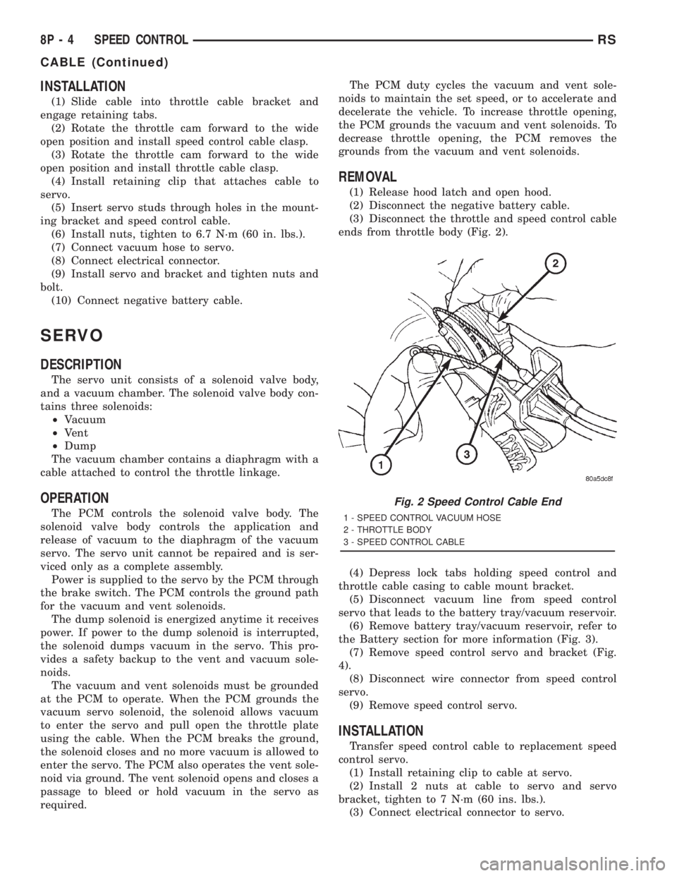
(3) Disconnect the throttle and speed control cable
ends from throttle body (Fig. 2).
(4) Depress lock tabs holding speed control and
throttle cable casing to cable mount bracket.
(5) Disconnect vacuum line from speed control
servo that leads to the battery tray/vacuum reservoir.
(6) Remove battery tray/vacuum reservoir, refer to
the Battery section for more information (Fig. 3).
(7) Remove speed control servo and bracket (Fig.
4).
(8) Disconnect wire connector from speed control
servo.
(9) Remove speed control servo.
INSTALLATION
Transfer speed control cable to replacement speed
control servo.
(1) Install retaining clip to cable at servo.
(2) Install 2 nuts at cable to servo and servo
bracket, tighten to 7 N´m (60 ins. lbs.).
(3) Connect electrical connector to servo.
Fig. 2 Speed Control Cable End
1 - SPEED CONTROL VACUUM HOSE
2 - THROTTLE BODY
3 - SPEED CONTROL CABLE
8P - 4 SPEED CONTROLRS
CABLE (Continued)
Page 2067 of 4284

(4) Connect vacuum line to speed control servo
that leads to the battery tray/vacuum reservoir.
(5) Install speed control servo and bracket.
(6) Install battery tray/vacuum reservoir, refer to
the Battery section for more information.
(7) Install speed control and throttle cable casing
to cable mount bracket.
(8) Connect the throttle and speed control cable
ends to throttle body.
(9) Connect the negative battery cable.
SWITCH
DESCRIPTION
There are two separate switch pods that operate
the speed control system and are located on the
steering wheel.
OPERATION
The speed control system has five separate resis-
tive switches that provide a single multiplexed
(MUX) voltage inputs to the PCM.The switch names
are: ON, OFF, SET, COAST, RESUME, ACCEL, TAP-
UP, COAST, and CANCEL. Based on conditions when
the buttons are pushed (and released), the five volt-
ages ranges provided to the PCM result in the follow-
ing functions: ON, OFF, SET, COAST, RESUME,
ACCEL, TAP-UP, COAST, and CANCEL. Refer to the
Speed Control Section for more information
Also the PCM receives an input from the brake
switch to sense whether the brake pedal has been
depressed. When the PCM receives the brake
depressed input, it turns off power to the speed con-
trol servo and disengages speed control.
The individual switches cannot be repaired. If one
switch fails, the entire switch module must be
replaced.
REMOVAL
The speed control switches are mounted in the
steering wheel and wired through the clock spring
device under the airbag module.
WARNING: IF REMOVAL OF AIRBAG MODULE IS
NECESSARY, REFER TO THE RESTRAINT SYS-
TEMS SECTION FOR MORE INFORMATION.
(1) Remove the negative battery cable.
(2) Turn off ignition.
(3) Remove the air bag, refer to the restraint sec-
tion for more information.
(4) Remove two screws from side of the switch.
(5) Remove switch from steering wheel.
(6) Disconnect two-way electrical connector.
(7) Repeat for the other switch.
INSTALLATION
The speed control switches are mounted in the
steering wheel and wired through the clock spring
device under the airbag module.
WARNING: IF REMOVAL OF AIRBAG MODULE IS
NECESSARY, REFER TO THE RESTRAINT SYS-
TEMS SECTION FOR MORE INFORMATION.
(1) Connect two-way electrical connector.
(2) Install switch.
Fig. 3 BATTERY TRAY/VACUUM RESERVOIR
Fig. 4 SPEED CONTROL SERVO
RSSPEED CONTROL8P-5
SERVO (Continued)
Page 2068 of 4284
(3) Install screws for the switch.
(4) Repeat for the other switch.
(5) Install the air bag, refer to the restraint section
for more information.
(6) Install the negative battery cable.
VACUUM RESERVOIR
DESCRIPTION
The vacuum reservoir is located in the engine com-
partment. It is made of plastic.
OPERATION
The reservoir stores engine vacuum. When engine
vacuum drops, as in climbing a grade while driving,
the reservoir supplies the vacuum needed to main-
tain proper speed control operation. The vacuum res-
ervoir cannot be repaired and must be replaced if
faulty.
REMOVAL
(1) Release hood latch and open hood.
(2) Disconnect the negative battery cable.
(3) Disconnect the vacuum line to the battery tray/
vacuum reservoir.
(4) Remove battery tray/vacuum reservoir, refer to
the Battery section for more information.
INSTALLATION
(1) Install battery tray/vacuum reservoir, refer to
the Battery section for more information.
(2) Connect vacuum line that leads to the battery
tray/vacuum reservoir.
(3) Connect the negative battery cable.
8P - 6 SPEED CONTROLRS
SWITCH (Continued)
Page 2069 of 4284
VEHICLE THEFT SECURITY
TABLE OF CONTENTS
page page
VEHICLE THEFT SECURITY
DESCRIPTION............................1
OPERATION.............................1
DIAGNOSIS AND TESTING..................2
SENTRY KEY IMMOBILIZER SYSTEM........2
VEHICLE THEFT SECURITY SYSTEM........3
HOOD AJAR SWITCH
REMOVAL...............................3
INSTALLATION............................3TRANSPONDER KEY
DESCRIPTION............................3
OPERATION.............................4
STANDARD PROCEDURE...................4
TRANSPONDER PROGRAMMING...........4
VTSS/SKIS INDICATOR LAMP
DESCRIPTION............................5
OPERATION.............................5
VEHICLE THEFT SECURITY
DESCRIPTION
VEHICLE THEFT SECURITY SYSTEM
The Vehicle Theft Security System (VTSS) is
designed to protect against whole vehicle theft. The
system monitors vehicle doors, hood, liftgate, and
ignition action for unauthorized operation. The alarm
activates:
²Sounding of the horn
²Flashing of the park and tail lamps
²Flashing of the headlamps
²An engine kill feature (without SKIS)
SENTRY KEY IMMOBILIZER SYSTEM
The Sentry Key Immobilizer System (SKIS) is
available as a factory-installed option on this vehicle.
It is designed to provide passive protection against
unauthorized vehicle use by disabling the engine,
after two (2) seconds of running, whenever an invalid
key is used to start the vehicle. The SKIS is active
whenever the ignition is on and does not require any
customer intervention. The primary components of
the system are the Sentry Key Immobilizer Module
(SKIM), Sentry Key (ignition key w/ a transponder
molded into the head), indicator light, Body Control
Module (BCM), and the Powertrain Control Module
(PCM). The SKIM is mounted to the steering column
with the molded, integral antenna mounted on the
light halo surrounding the ignition lock cylinder. The
indicator light, is located in the message center.
OPERATION
VEHICLE THEFT SECURITY SYSTEM
Upon failure of proper SKIM communication to the
PCM, the PCM will shut off fuel after two seconds ofrun time. The engine will not re-crank on the key
cycle that the failure occurred, a full key down
sequence must be performed for the engine to crank
again. After six consecutive fuel shut-offs, the engine
will no longer crank on subsequent key cycles. The
failure must be corrected and a valid communication
process between the SKIM and the PCM must occur
for the engine to crank and start again.
The electronics for the VTSS are part of the Body
Control Module (BCM). The system is armed when
the vehicle is locked using the:
²Power door lock switches (with any door ajar)
²Remote Keyless Entry transmitter.
²Door Cylinder Lock Switches.
For vehicles equipped with SKIS, the doors do not
have to be locked to enable the fuel shut off feature.
After the vehicle is locked and the last door is
closed, the set LED indicator in the top cover will
flash quickly for 16 seconds, indicating that arming
is in progress. If no monitored systems are activated
during this period, the system will arm. The LED
will extinguish unless the liftgate is open. If the lift-
gate is open, the LED will flash at a slower rate.
This indicates that the system is armed. If fault is
detected on any key cylinder input, the indicator
LED will remain solid during the arming process,
although the system will still arm. If the indicator
LED does not illuminate at all upon door closing it
indicates that the system is not arming.
Passive disarming occurs upon normal vehicle
entry by unlocking either door with the ignition key/
remote transmitter. This disarming will also halt the
alarm once it has been activated.
A tamper alert exists to notify the driver that the
VTSS had been activated. This alert consists of 3
horn pulses when the vehicle is disarmed.
RSVEHICLE THEFT SECURITY8Q-1
Page 2070 of 4284
NOTE: The VTSS will not arm by pushing down the
door lock mechanism. This will manually override
the system.
For Door Cylinder Lock Switch Removal and
Installation, refer to Electrical, Power Locks, Door
Cylinder Lock Switch.
If the VTSS is triggered, the horn will pulse, head-
lamps/marker lamps will flash, and the VTSS warn-
ing lamp will flash. If BCM determines the threat to
be false and the VTSS is not triggered again, the sys-
tem will shut down and rearm itself after three min-
utes. If a trigger is still active, the alarm will
continue for an additional 15 minutes without the
horn. The VTSS monitoring portion of the system is
split into two sections. The engine compartment sec-
tion and the passenger compartment section. If a
malfunction occurs in the engine compartment sec-
tion, the passenger compartment section would still
arm and function normally.
NOTE: If hood is not secure during the arming
sequence, the lamp will stay lit and not flash. The
system will arm with hood not secured (hood ajar
switch closed) and the liftgate open (liftgate ajar
switch closed). System will not arm if passenger
compartment is not secure (all switches closed)
ARMING THE VTSS - METHOD A
(1) With the key removed from the ignition lock
and any door open (excluding liftgate), actuate one of
the following:
²Power door lock button to LOCK,
²Key fob LOCK button
²Door lock key cylinder to locked position.
(2) Close all opened doors. Liftgate can remain
open.
(3) After the last door is closed, an arming time-
out period of sixteen seconds will start, then the
VTSS will become armed.
ARMING THE VTSS - METHOD B
Actuating the key fob transmitter LOCK button,
key locking the front doors or liftgate with the doors
closed and the ignition locked will begin the arming
time-out period. If method A, 16 second time-out
sequence was in process when method B was actu-
ated, the 16 second time-out will restart from the
time of the second actuation.
If the security lamp does not illuminate at all upon
final door closure, it indicates that the system is not
arming.
The current VTSS status armed or disarmed shall
be maintained in memory to prevent battery discon-
nects from disarming the system.
TRIGGERING THE VTSS
After the VTSS is armed, the following actions will
trigger the alarm:
²Opening any door.
²Opening the hood
²Turning the ignition to the ON, ACC, or
UNLOCK position.
²Opening liftgate without first receiving a RKE
input or liftgate key input.
CAUTION: The VTSS indicator LED will trigger and
engine will continue to run if the vehicle is
equipped with SKIS and the proper key is used to
start the vehicle. This condition will occur if the
VTSS has been triggered. If valid key is used, VTSS
will disarm
SENTRY KEY IMMOBILIZER SYSTEM
The SKIS includes keys from the factory which are
pre-programmed. Each SKIM will recognize a maxi-
mum of eight Sentry Keys. If the customer would
like to own additional keys other than those provided
with the vehicle, they can be purchased from any
authorized dealer. These keys must be programmed
to the SKIM on the vehicle in order for the system to
recognize them as valid keys. This can be done by
the dealer with a DRB IIItscan tool or by a cus-
tomer if this feature is available in their market and
they have two (2) valid keys already available to
them. Refer to the Service Procedures portion of this
system for additional details. The SKIS performs a
self-test each time the ignition switch is turned to
the ON position and will store Diagnostic Trouble
Codes (DTC's) if a system malfunction is detected.
The SKIS can be diagnosed and any stored DTC's
can be retrieved using a DRB IIItscan tool as
described in the appropriate Body Diagnostic Proce-
dures manual.
DIAGNOSIS AND TESTING - SENTRY KEY
IMMOBILIZER SYSTEM
WARNING: ON VEHICLES EQUIPPED WITH AIR-
BAGS, REFER TO ELECTRICAL, RESTRAINTS,
WARNINGS, BEFORE ATTEMPTING COMPONENT
DIAGNOSIS OR SERVICE. FAILURE TO TAKE THE
PROPER PRECAUTIONS COULD RESULT IN ACCI-
DENTAL AIRBAG DEPLOYMENT AND POSSIBLE
PERSONAL INJURY.
8Q - 2 VEHICLE THEFT SECURITYRS
VEHICLE THEFT SECURITY (Continued)