differential CHRYSLER VOYAGER 2004 Service Manual
[x] Cancel search | Manufacturer: CHRYSLER, Model Year: 2004, Model line: VOYAGER, Model: CHRYSLER VOYAGER 2004Pages: 2585, PDF Size: 62.54 MB
Page 1956 of 2585
DRIVING CLUTCHES
DESCRIPTION
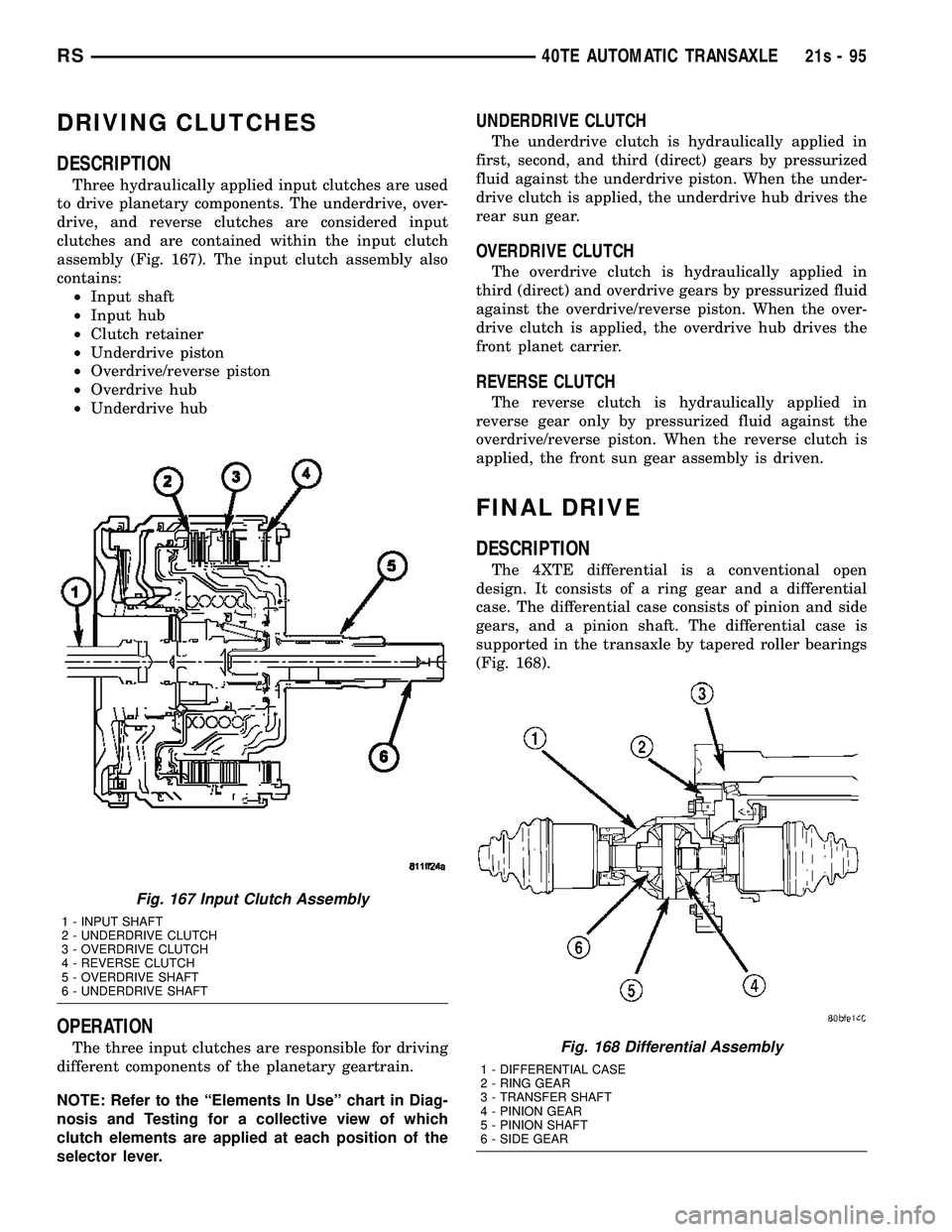
Three hydraulically applied input clutches are used
to drive planetary components. The underdrive, over-
drive, and reverse clutches are considered input
clutches and are contained within the input clutch
assembly (Fig. 167). The input clutch assembly also
contains: ² Input shaft
² Input hub
² Clutch retainer
² Underdrive piston
² Overdrive/reverse piston
² Overdrive hub
² Underdrive hub
OPERATION
The three input clutches are responsible for driving
different components of the planetary geartrain.
NOTE: Refer to the ªElements In Useº chart in Diag-
nosis and Testing for a collective view of which
clutch elements are applied at each position of the
selector lever.
UNDERDRIVE CLUTCH
The underdrive clutch is hydraulically applied in
first, second, and third (direct) gears by pressurized
fluid against the underdrive piston. When the under-
drive clutch is applied, the underdrive hub drives the
rear sun gear.
OVERDRIVE CLUTCH
The overdrive clutch is hydraulically applied in
third (direct) and overdrive gears by pressurized fluid
against the overdrive/reverse piston. When the over-
drive clutch is applied, the overdrive hub drives the
front planet carrier.
REVERSE CLUTCH
The reverse clutch is hydraulically applied in
reverse gear only by pressurized fluid against the
overdrive/reverse piston. When the reverse clutch is
applied, the front sun gear assembly is driven.
FINAL DRIVE
DESCRIPTION
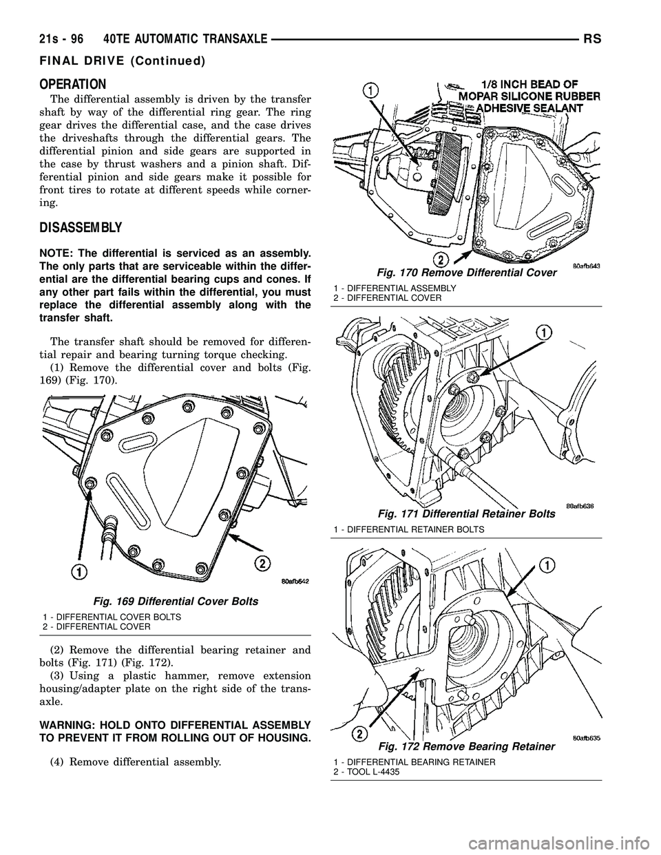
The 4XTE differential is a conventional open
design. It consists of a ring gear and a differential
case. The differential case consists of pinion and side
gears, and a pinion shaft. The differential case is
supported in the transaxle by tapered roller bearings
(Fig. 168).
Fig. 167 Input Clutch Assembly
1 - INPUT SHAFT
2 - UNDERDRIVE CLUTCH
3 - OVERDRIVE CLUTCH
4 - REVERSE CLUTCH
5 - OVERDRIVE SHAFT
6 - UNDERDRIVE SHAFT
Fig. 168 Differential Assembly
1 - DIFFERENTIAL CASE
2 - RING GEAR
3 - TRANSFER SHAFT
4 - PINION GEAR
5 - PINION SHAFT
6 - SIDE GEAR
RS 40TE AUTOMATIC TRANSAXLE21s-95
Page 1957 of 2585
OPERATION
The differential assembly is driven by the transfer
shaft by way of the differential ring gear. The ring
gear drives the differential case, and the case drives
the driveshafts through the differential gears. The
differential pinion and side gears are supported in
the case by thrust washers and a pinion shaft. Dif-
ferential pinion and side gears make it possible for
front tires to rotate at different speeds while corner-
ing.
DISASSEMBLY
NOTE: The differential is serviced as an assembly.
The only parts that are serviceable within the differ-
ential are the differential bearing cups and cones. If
any other part fails within the differential, you must
replace the differential assembly along with the
transfer shaft.
The transfer shaft should be removed for differen-
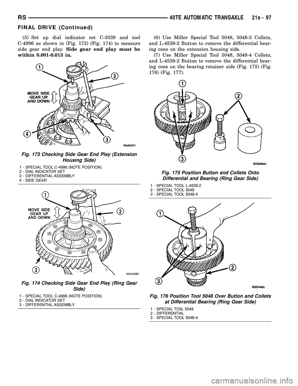
tial repair and bearing turning torque checking. (1) Remove the differential cover and bolts (Fig.
169) (Fig. 170).
(2) Remove the differential bearing retainer and
bolts (Fig. 171) (Fig. 172). (3) Using a plastic hammer, remove extension
housing/adapter plate on the right side of the trans-
axle.
WARNING: HOLD ONTO DIFFERENTIAL ASSEMBLY
TO PREVENT IT FROM ROLLING OUT OF HOUSING.
(4) Remove differential assembly.
Fig. 169 Differential Cover Bolts
1 - DIFFERENTIAL COVER BOLTS
2 - DIFFERENTIAL COVER
Fig. 170 Remove Differential Cover
1 - DIFFERENTIAL ASSEMBLY
2 - DIFFERENTIAL COVER
Fig. 171 Differential Retainer Bolts
1 - DIFFERENTIAL RETAINER BOLTS
Fig. 172 Remove Bearing Retainer
1 - DIFFERENTIAL BEARING RETAINER
2 - TOOL L-4435
21s - 96 40TE AUTOMATIC TRANSAXLERS
FINAL DRIVE (Continued)
Page 1958 of 2585
(5) Set up dial indicator set C-3339 and tool
C-4996 as shown in (Fig. 173) (Fig. 174) to measure
side gear end play. Side gear end play must be
within 0.001-0.013 in. (6) Use Miller Special Tool 5048, 5048-3 Collets,
and L-4539-2 Button to remove the differential bear-
ing cone on the extension housing side. (7) Use Miller Special Tool 5048, 5048-4 Collets,
and L-4539-2 Button to remove the differential bear-
ing cone on the bearing retainer side (Fig. 175) (Fig.
176) (Fig. 177).
Fig. 173 Checking Side Gear End Play (Extension Housing Side)
1 - SPECIAL TOOL C-4996 (NOTE POSITION)
2 - DIAL INDICATOR SET
3 - DIFFERENTIAL ASSEMBLY
4 - SIDE GEAR
Fig. 174 Checking Side Gear End Play (Ring Gear Side)
1 - SPECIAL TOOL C-4996 (NOTE POSITION)
2 - DIAL INDICATOR SET
3 - DIFFERENTIAL ASSEMBLY
Fig. 175 Position Button and Collets OntoDifferential and Bearing (Ring Gear Side)
1 - SPECIAL TOOL L-4539-2
2 - SPECIAL TOOL 5048
3 - SPECIAL TOOL 5048-4
Fig. 176 Position Tool 5048 Over Button and Collets at Differential Bearing (Ring Gear Side)
1 - SPECIAL TO0L 5048
2 - DIFFERENTIAL
3 - SPECIAL TOOL 5048-4
RS 40TE AUTOMATIC TRANSAXLE21s-97
FINAL DRIVE (Continued)
Page 1959 of 2585
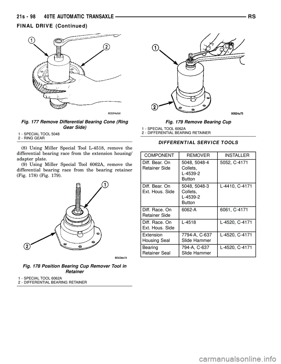
(8) Using Miller Special Tool L-4518, remove the
differential bearing race from the extension housing/
adapter plate. (9) Using Miller Special Tool 6062A, remove the
differential bearing race from the bearing retainer
(Fig. 178) (Fig. 179).
DIFFERENTIAL SERVICE TOOLS
COMPONENT REMOVER INSTALLER
Diff. Bear. On
Retainer Side 5048, 5048-4
Collets,
L-4539-2
Button5052, C-4171
Diff. Bear. On
Ext. Hous. Side 5048, 5048-3
Collets,
L-4539-2
ButtonL-4410, C-4171
Diff. Race. On
Retainer Side 6062-A 6061, C-4171
Diff. Race. On
Ext. Hous. Side L-4518 L-4520, C-4171
Extension
Housing Seal 7794-A, C-637
Slide HammerL-4520, C-4171
Bearing
Retainer Seal 794-A, C-637
Slide HammerL-4520, C-4171
Fig. 177 Remove Differential Bearing Cone (Ring
Gear Side)
1 - SPECIAL TOOL 5048
2 - RING GEAR
Fig. 178 Position Bearing Cup Remover Tool in Retainer
1 - SPECIAL TOOL 6062A
2 - DIFFERENTIAL BEARING RETAINER
Fig. 179 Remove Bearing Cup
1 - SPECIAL TOOL 6062A
2 - DIFFERENTIAL BEARING RETAINER
21s - 98 40TE AUTOMATIC TRANSAXLERS
FINAL DRIVE (Continued)
Page 1960 of 2585
ASSEMBLY
NOTE: The differential is serviced as an assembly.
The only parts that are serviceable within the differ-
ential are the differential bearing cups and cones. If
any other part fails within the differential, you must
replace the differential assembly along with the
transfer shaft.
NOTE: Use MoparTATF RTV (MS-GF41), or equiva-
lent, on retainer and extension housing/adapter
plate to seal to case.
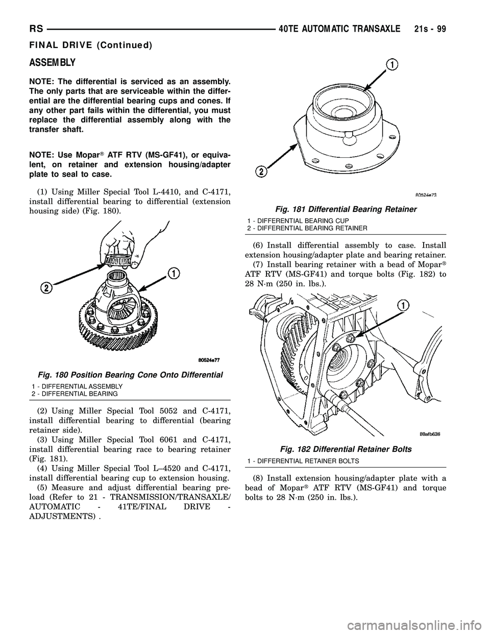
(1) Using Miller Special Tool L-4410, and C-4171,
install differential bearing to differential (extension
housing side) (Fig. 180).
(2) Using Miller Special Tool 5052 and C-4171,
install differential bearing to differential (bearing
retainer side). (3) Using Miller Special Tool 6061 and C-4171,
install differential bearing race to bearing retainer
(Fig. 181). (4) Using Miller Special Tool L±4520 and C-4171,
install differential bearing cup to extension housing. (5) Measure and adjust differential bearing pre-
load (Refer to 21 - TRANSMISSION/TRANSAXLE/
AUTOMATIC - 41TE/FINAL DRIVE -
ADJUSTMENTS) . (6) Install differential assembly to case. Install
extension housing/adapter plate and bearing retainer. (7) Install bearing retainer with a bead of Mopar t
ATF RTV (MS-GF41) and torque bolts (Fig. 182) to
28 N´m (250 in. lbs.).
(8) Install extension housing/adapter plate with a
bead of Mopar tATF RTV (MS-GF41) and torque
bolts to 28 N´m (250 in. lbs.).
Fig. 180 Position Bearing Cone Onto Differential
1 - DIFFERENTIAL ASSEMBLY
2 - DIFFERENTIAL BEARING
Fig. 181 Differential Bearing Retainer
1 - DIFFERENTIAL BEARING CUP
2 - DIFFERENTIAL BEARING RETAINER
Fig. 182 Differential Retainer Bolts
1 - DIFFERENTIAL RETAINER BOLTS
RS 40TE AUTOMATIC TRANSAXLE21s-99
FINAL DRIVE (Continued)
Page 1961 of 2585
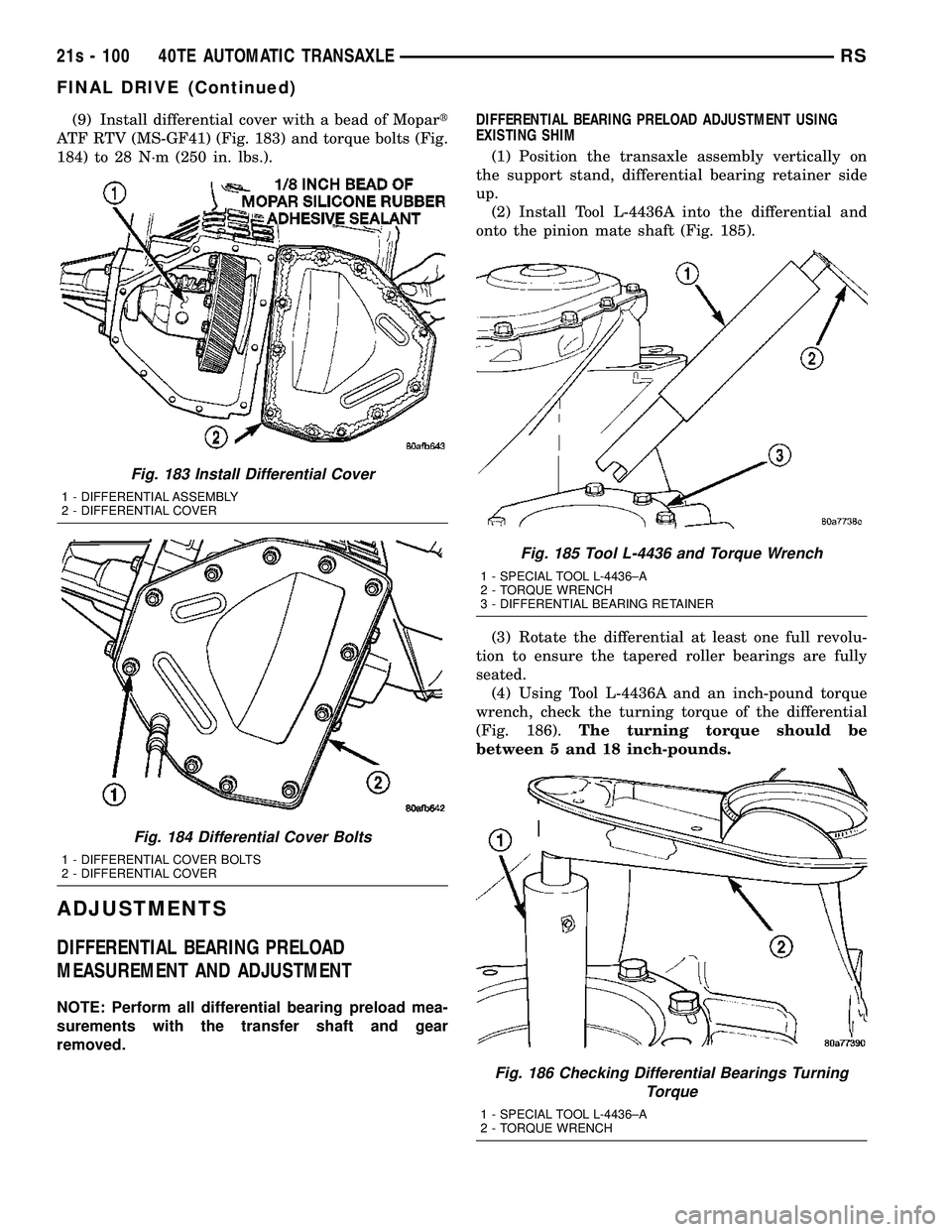
(9) Install differential cover with a bead of Mopart
ATF RTV (MS-GF41) (Fig. 183) and torque bolts (Fig.
184) to 28 N´m (250 in. lbs.).
ADJUSTMENTS
DIFFERENTIAL BEARING PRELOAD
MEASUREMENT AND ADJUSTMENT
NOTE: Perform all differential bearing preload mea-
surements with the transfer shaft and gear
removed. DIFFERENTIAL BEARING PRELOAD ADJUSTMENT USING
EXISTING SHIM
(1) Position the transaxle assembly vertically on
the support stand, differential bearing retainer side
up. (2) Install Tool L-4436A into the differential and
onto the pinion mate shaft (Fig. 185).
(3) Rotate the differential at least one full revolu-
tion to ensure the tapered roller bearings are fully
seated. (4) Using Tool L-4436A and an inch-pound torque
wrench, check the turning torque of the differential
(Fig. 186). The turning torque should be
between 5 and 18 inch-pounds.
Fig. 183 Install Differential Cover
1 - DIFFERENTIAL ASSEMBLY
2 - DIFFERENTIAL COVER
Fig. 184 Differential Cover Bolts
1 - DIFFERENTIAL COVER BOLTS
2 - DIFFERENTIAL COVER
Fig. 185 Tool L-4436 and Torque Wrench
1 - SPECIAL TOOL L-4436±A
2 - TORQUE WRENCH
3 - DIFFERENTIAL BEARING RETAINER
Fig. 186 Checking Differential Bearings Turning Torque
1 - SPECIAL TOOL L-4436±A
2 - TORQUE WRENCH
21s - 100 40TE AUTOMATIC TRANSAXLERS
FINAL DRIVE (Continued)
Page 1962 of 2585
(5) If the turning torque is within specifications,
remove tools. Setup is complete. (6) If turning torque is not within specifications
proceed with the following steps. (a) Remove differential bearing retainer from
the transaxle case. (b) Remove the bearing cup from the differential
bearing retainer using Tool 6062A. (c) Remove the existing shim from under the
cup. (d) Measure the existing shim.
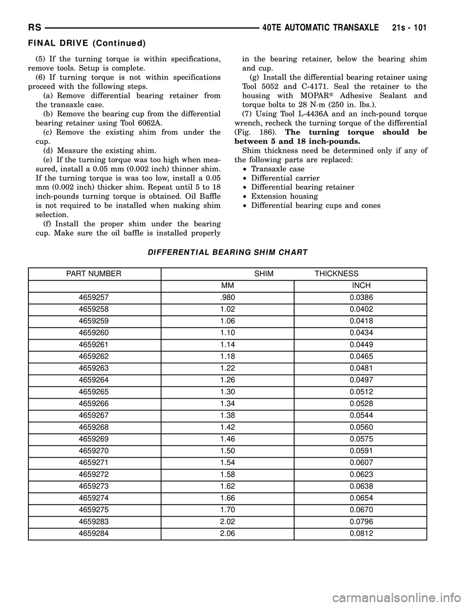
(e) If the turning torque was too high when mea-
sured, install a 0.05 mm (0.002 inch) thinner shim.
If the turning torque is was too low, install a 0.05
mm (0.002 inch) thicker shim. Repeat until 5 to 18
inch-pounds turning torque is obtained. Oil Baffle
is not required to be installed when making shim
selection. (f) Install the proper shim under the bearing
cup. Make sure the oil baffle is installed properly in the bearing retainer, below the bearing shim
and cup.
(g) Install the differential bearing retainer using
Tool 5052 and C-4171. Seal the retainer to the
housing with MOPAR tAdhesive Sealant and
torque bolts to 28 N´m (250 in. lbs.).
(7) Using Tool L-4436A and an inch-pound torque
wrench, recheck the turning torque of the differential
(Fig. 186). The turning torque should be
between 5 and 18 inch-pounds. Shim thickness need be determined only if any of
the following parts are replaced: ² Transaxle case
² Differential carrier
² Differential bearing retainer
² Extension housing
² Differential bearing cups and cones
DIFFERENTIAL BEARING SHIM CHART
PART NUMBER SHIM THICKNESS
MM INCH
4659257 .980 0.0386
4659258 1.02 0.0402
4659259 1.06 0.0418
4659260 1.10 0.0434
4659261 1.14 0.0449
4659262 1.18 0.0465
4659263 1.22 0.0481
4659264 1.26 0.0497
4659265 1.30 0.0512
4659266 1.34 0.0528
4659267 1.38 0.0544
4659268 1.42 0.0560
4659269 1.46 0.0575
4659270 1.50 0.0591
4659271 1.54 0.0607
4659272 1.58 0.0623
4659273 1.62 0.0638
4659274 1.66 0.0654
4659275 1.70 0.0670
4659283 2.02 0.0796
4659284 2.06 0.0812
RS 40TE AUTOMATIC TRANSAXLE21s - 101
FINAL DRIVE (Continued)
Page 1963 of 2585

PRELOAD ADJUSTMENT W/O SHIM(1) Remove the bearing cup from the differential
bearing retainer using Miller special Tool 6062A. (2) Remove existing shim from under bearing cup.
(3) Reinstall the bearing cup into the retainer
using Miller Special Tool 6061, and C-4171.
NOTE: Oil baffle is not required when making the
shim calculation.
(4) Install the bearing retainer into the case.
Torque bolts to 28 N ²m (250 in. lbs.).
(5) Position the transaxle assembly vertically on
the support stand and install Miller Special Tool
L-4436-A into the bearing retainer. (6) Rotate the differential at least one full revolu-
tion to ensure the tapered roller bearings are fully
seated. (7) Attach a dial indicator to the case and zero the
dial. Place the tip on the end of Special Tool
L-4436-A. (8) Place a large screwdriver to each side of the
ring gear and lift. Check the dial indicator for the
amount of end play.
CAUTION: Do not damage the transaxle case and/or
differential retainer sealing surface.
(9) Using the end play measurement that was
determined, add 0.18mm (0.007 inch). This should
give you between 5 and 18 inch pounds of bearing
preload. Refer to the Differential Bearing Shim Chart
to determine which shim to use. (10) Remove the differential bearing retainer.
Remove the bearing cup. (11) Install the oil baffle. Install the proper shim
combination under the bearing cup. (12) Install the differential bearing retainer. Seal
the retainer to the housing with Mopar tSilicone
Rubber Adhesive Sealant. Torque bolts to 28 N ²m
(250 in. lbs.). (13) Using Miller Special Tool L-4436-A and an
inch-pound torque wrench, check the turning torque
of the differential (Fig. 186). The turning torque
should be between 5-18 inch-pounds.
NOTE: If turning torque is too high install a 0.05mm
(0.002 inch) thicker shim. If the turning torque is too
low, install a 0.05mm (0.002 inch) thinner shim.
Repeat until 5-18 inch-pounds of turning torque is
obtained.FLUID
STANDARD PROCEDURE
FLUID LEVEL AND CONDITION CHECK
NOTE: Only transmission fluid of the type labeled
Mopar ATF+4 (Automatic Transmission Fluid)
should be used in this transaxle.
FLUID LEVEL CHECK
The transmission sump has a fluid level indicator
(dipstick) to check oil similar to most automatic
transmissions. It is located on the left side of the
engine. Be sure to wipe all dirt from dipstick handle
before removing. The torque converter fills in both the P Park and N
Neutral positions. Place the selector lever in P Park
to be sure that the fluid level check is accurate. The
engine should be running at idle speed for at
least one minute, with the vehicle on level
ground. At normal operating temperature 82É C
(180É F), the fluid level is correct if it is in the HOT
region on the oil level indicator (Fig. 187). The fluid
level should be within the COLD region of the dip-
stick at 27É C (80É F) fluid temperature.
FLUID LEVEL CHECK USING DRB
NOTE: Engine and Transaxle should be at normal
operating temperature before performing this proce-
dure.
(1) Start engine and apply parking brake.
(2) Hook up DRB scan tool and select transmis-
sion.
Fig. 187 Fluid Level Indicator
1 - FLUID LEVEL INDICATOR
21s - 102 40TE AUTOMATIC TRANSAXLERS
FINAL DRIVE (Continued)
Page 2027 of 2585
41TE AUTOMATIC TRANSAXLE
TABLE OF CONTENTS
page page
41TE AUTOMATIC TRANSAXLE DISASSEMBLY ........................166
ASSEMBLY ...........................184
ACCUMULATOR DESCRIPTION ........................206 VALVE BODY
REMOVAL ............................206
DISASSEMBLY ........................208
ASSEMBLY ...........................212
INSTALLATION ........................217
41TE AUTOMATIC
TRANSAXLE
DISASSEMBLY
NOTE: If transaxle is being overhauled (clutch and/or
seal replacement) or replaced, it is necessary to per-
form the PCM/TCM Quick Learn Procedure. (Refer to 8 -
ELECTRICAL/ELECTRONIC CONTROL MODULES/POW-
ERTRAIN/TRANSMISSION CONTROL MODULE - STAN-
DARD PROCEDURE)
NOTE: This procedure does not include final drive
(differential) disassembly.
(1) Remove input and output speed sensors.
(2) Remove three (3) solenoid/pressure switch
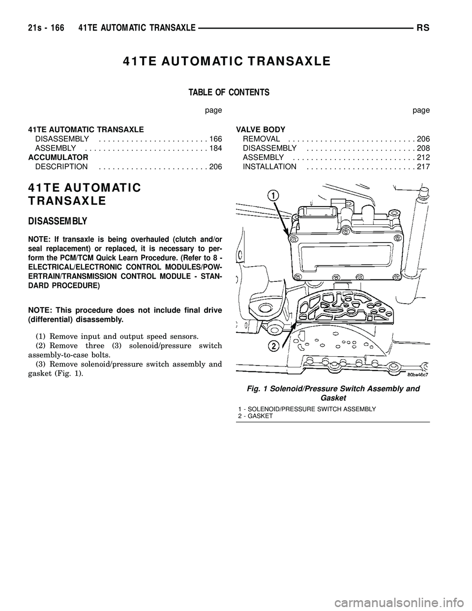
assembly-to-case bolts. (3) Remove solenoid/pressure switch assembly and
gasket (Fig. 1).
Fig. 1 Solenoid/Pressure Switch Assembly and Gasket
1 - SOLENOID/PRESSURE SWITCH ASSEMBLY
2 - GASKET
21s - 166 41TE AUTOMATIC TRANSAXLERS
Page 2546 of 2585

BASE COAT/CLEARCOAT FINISH -
DESCRIPTION.......................23-85
BATTERY - DESCRIPTION...............8F-7
BATTERY - DIAGNOSIS AND TESTING.....8F-9
BATTERY - OPERATION.................8F-9
BATTERY - REMOVAL............8F-14,8F-15
BATTERY - SPECIFICATIONS.............8N-5
BATTERY CABLE - DIAGNOSIS AND
TESTING...........................8F-16
BATTERY CABLES - DESCRIPTION.......8F-16
BATTERY CABLES - INSTALLATION.......8F-18
BATTERY CABLES - OPERATION.........8F-16
BATTERY CABLES - REMOVAL..........8F-18
BATTERY CHARGING - STANDARD
PROCEDURE, CONVENTIONAL..........8F-11
BATTERY CHARGING - STANDARD
PROCEDURE, SPIRAL PLATE............8F-10
BATTERY ELECTROLYTE LEVEL -
STANDARD PROCEDURE, CHECKING.....8F-14
BATTERY HOLDDOWN - DESCRIPTION....8F-15
BATTERY HOLDDOWN - INSTALLATION . . . 8F-16
BATTERY HOLDDOWN - OPERATION.....8F-15
BATTERY HOLDDOWN - REMOVAL . . 8F-15,8F-16
BATTERY REPLACEMENT - STANDARD
PROCEDURE....................8N-42,8N-5
BATTERY, SPECIFICATIONS.............8N-43
BATTERY SYSTEM - CLEANING.......8F-4,8F-5
BATTERY SYSTEM - DESCRIPTION........8F-1
BATTERY SYSTEM - DIAGNOSIS AND
TESTING............................8F-2
BATTERY SYSTEM - INSPECTION.....8F-5,8F-6
BATTERY SYSTEM - OPERATION.........8F-2
BATTERY SYSTEM - SPECIFICATIONS......8F-6
BATTERY SYSTEM SPECIAL TOOLS,
SPECIAL TOOLS......................8F-7
BATTERY TEMPERATURE SENSOR -
DESCRIPTION.......................8F-23
BATTERY TEMPERATURE SENSOR -
OPERATION.........................8F-23
BATTERY TEMPERATURE SENSOR -
REMOVAL..........................8F-23
BATTERY TEMPERATURE SENSOR -
SPECIFICATIONS.....................8F-22
BATTERY TRAY - DESCRIPTION.........8F-18
BATTERY TRAY - INSTALLATION.........8F-19
BATTERY TRAY - OPERATION......8F-18,8F-19
BATTERY TRAY - REMOVAL............8F-19
BEARING - DESCRIPTION, HUB.......2-30,2-4
BEARING - DIAGNOSIS AND TESTING,
HUB.............................2-31,2-5
BEARING - INSTALLATION, CLUTCH
RELEASE LEVER.......................6-7
BEARING - INSTALLATION, END COVER
BALL..............................21-10
BEARING - INSTALLATION, HUB.......2-33,2-6
BEARING - OPERATION, HUB.........2-30,2-4
BEARING - REMOVAL, CLUTCH RELEASE
LEVER...............................6-6
BEARING - REMOVAL, END COVER BALL . . . 21-9
BEARING - REMOVAL, HUB..........2-31,2-5
BEARING CLEARANCE - STANDARD
PROCEDURE, MEASURING
CONNECTING ROD...................9-120
BEARING CLEARANCE USING
PLASTIGAGE - STANDARD
PROCEDURE, MEASURING..........9-12,9-84
BEARING FITTING - STANDARD
PROCEDURE, MAIN...................9-123
BEARING PRELOAD - ADJUSTMENT,
DIFFERENTIAL......................21-199
BEARING PRELOAD MEASUREMENT
AND ADJUSTMENT, ADJUSTMENTS -
DIFFERENTIAL.....................21s-100
BEARINGS - INSTALLATION,
CRANKSHAFT MAIN..................9-124
BEARINGS - REMOVAL, CRANKSHAFT
MAIN..............................9-124
BEARINGS (IN BLOCK) - DESCRIPTION,
CAMSHAFT.........................9-115
BEARINGS (IN BLOCK) - INSPECTION,
CAMSHAFT
.........................9-115
BEARINGS (IN BLOCK) - INSTALLATION,
CAMSHAFT
.........................9-115
BEARINGS (IN BLOCK) - OPERATION,
CAMSHAFT
.........................9-115
BEARINGS (IN BLOCK) - REMOVAL,
CAMSHAFT
.........................9-115
BELLCRANK - INSTALLATION
...........23-35BELLCRANK - REMOVAL...............23-35
BELT - DIAGNOSIS AND TESTING,
ACCESSORY DRIVE.....................7-7
BELT - INSTALLATION, TIMING...........9-65
BELT - REMOVAL, TIMING..............9-63
BELT & RETRACTOR - FIRST ROW -
OUTBOARD - INSTALLATION, SEAT......8O-14
BELT & RETRACTOR - FIRST ROW -
OUTBOARD - REMOVAL, SEAT..........8O-14
BELT & RETRACTOR - OUTBOARD -
FRONT - INSTALLATION, SEAT..........8O-14
BELT & RETRACTOR - OUTBOARD -
FRONT - REMOVAL, SEAT..............8O-14
BELT & RETRACTOR - SECOND ROW -
LEFT OUTBOARD - INSTALLATION,
SEAT ..............................8O-17
BELT & RETRACTOR - SECOND ROW -
LEFT OUTBOARD - REMOVAL, SEAT.....8O-17
BELT & RETRACTOR - SECOND ROW -
RIGHT OUTBOARD - INSTALLATION,
SEAT ..............................8O-15
BELT & RETRACTOR - SECOND ROW -
RIGHT OUTBOARD - REMOVAL, SEAT....8O-15
BELT & RETRACTOR - SECOND ROW -
RIGHT OUTBOARD WITH REAR HVAC -
LWB - INSTALLATION, SEAT............8O-16
BELT & RETRACTOR - SECOND ROW -
RIGHT OUTBOARD WITH REAR HVAC -
LWB - REMOVAL, SEAT...............8O-16
BELT BUCKLE - FIRST ROW - BENCH -
INSTALLATION, SEAT.................8O-13
BELT BUCKLE - FIRST ROW - BENCH -
REMOVAL, SEAT.....................8O-13
BELT BUCKLE - FIRST ROW INBOARD -
QUAD BUCKET - INSTALLATION, SEAT....8O-12
BELT BUCKLE - FIRST ROW INBOARD -
QUAD BUCKET - REMOVAL, SEAT.......8O-12
BELT BUCKLE - FRONT INBOARD -
INSTALLATION, SEAT.................8O-12
BELT BUCKLE - FRONT INBOARD -
REMOVAL, SEAT.....................8O-12
BELT BUCKLE - SECOND ROW - THREE
PASSENGER BENCH - INSTALLATION,
SEAT ..............................8O-15
BELT BUCKLE - SECOND ROW - THREE
PASSENGER BENCH - REMOVAL, SEAT . . . 8O-15
BELT BUCKLE - SECOND ROW INBOARD
- 50/50 BENCH - INSTALLATION, SEAT . . . 8O-13
BELT BUCKLE - SECOND ROW INBOARD
- 50/50 BENCH - REMOVAL, SEAT.......8O-13
BELT COVER(S) - INSTALLATION,
TIMING.............................9-62
BELT COVER(S) - REMOVAL, TIMING......9-61
BELT HEIGHT ADJUSTER-BOR
C-PILLAR - INSTALLATION, SEAT........8O-13
BELT HEIGHT ADJUSTER-BOR
C-PILLAR - REMOVAL, SEAT...........8O-13
BELT HEIGHT ADJUSTER KNOB -
INSTALLATION, SEAT.................8O-14
BELT HEIGHT ADJUSTER KNOB -
REMOVAL, SEAT.....................8O-14
BELT MOLDING - INSTALLATION, FRONT
DOOR INNER.......................23-115
BELT MOLDING - INSTALLATION, FRONT
DOOR OUTER......................23-113
BELT MOLDING - REMOVAL, FRONT
DOOR INNER.......................23-115
BELT MOLDING - REMOVAL, FRONT
DOOR OUTER......................23-113
BELT TENSION - STANDARD
PROCEDURE, CHECKING POWER
STEERING............................7-8
BELT TENSION, SPECIFICATIONS -
ACCESSORY DRIVE.....................7-5
BELT TENSIONER - 2.4L - INSTALLATION . . 7-10
BELT TENSIONER - 2.4L - REMOVAL......7-10
BELT TENSIONER - 3.3/3.8L -
INSTALLATION........................7-12
BELT TENSIONER - 3.3/3.8L - REMOVAL . . . 7-12
BELT TENSIONER - DESCRIPTION, SEAT . . 8O-17
BELT TENSIONER - OPERATION, SEAT....8O-17
BELT TENSIONER & PULLEY -
INSTALLATION, TIMING
.................9-69
BELT TENSIONER & PULLEY -
REMOVAL, TIMING
....................9-68
BELTS - 2.4L - ADJUSTMENTS, DRIVE
.....7-10
BELTS - 2.4L - CLEANING, DRIVE
..........7-9
BELTS - 2.4L - INSPECTION, DRIVE
........7-9BELTS - 2.4L - INSTALLATION, DRIVE.....7-10
BELTS - 2.4L - REMOVAL, DRIVE..........7-8
BELTS - 3.3/3.8L - CLEANING, DRIVE......7-11
BELTS - 3.3/3.8L - INSPECTION, DRIVE....7-11
BELTS - 3.3/3.8L - INSTALLATION, DRIVE . . 7-12
BELTS - 3.3/3.8L - REMOVAL, DRIVE......7-11
BENCH - INSTALLATION, SEAT BACK
HINGE COVERS - QUAD BUCKET, 50/50
SPLIT.............................23-101
BENCH - INSTALLATION, SEAT BELT
BUCKLE - FIRST ROW................8O-13
BENCH - INSTALLATION, SEAT BELT
BUCKLE - SECOND ROW - THREE
PASSENGER........................8O-15
BENCH - INSTALLATION, SEAT BELT
BUCKLE - SECOND ROW INBOARD -
50/50..............................8O-13
BENCH - INSTALLATION, SEAT CUSHION
COVER - QUAD BUCKET, 50/50 SPLIT . . . 23-100
BENCH - REMOVAL, SEAT BACK HINGE
COVERS - QUAD BUCKET, 50/50 SPLIT . . 23-101
BENCH - REMOVAL, SEAT BELT BUCKLE
- FIRST ROW.......................8O-13
BENCH - REMOVAL, SEAT BELT BUCKLE
- SECOND ROW - THREE PASSENGER....8O-15
BENCH - REMOVAL, SEAT BELT BUCKLE
- SECOND ROW INBOARD - 50/50.......8O-13
BENCH - REMOVAL, SEAT CUSHION
COVER - QUAD BUCKET, 50/50 SPLIT . . . 23-100
BENCH SEAT - REMOVAL, CHILD SEAT
MODULE...........................23-87
BENCH SEAT BACK - INSTALLATION.....23-103
BENCH SEAT BACK - REMOVAL........23-103
BENCH SEAT BACK COVER -
INSTALLATION......................23-103
BENCH SEAT BACK COVER - REMOVAL . . 23-103
BENCH SEAT BACK HINGE - REMOVAL . . 23-102
BENCH SEAT RISER - 50/50 SPLIT -
INSTALLATION......................23-100
BENCH SEAT RISER - 50/50 SPLIT -
REMOVAL.........................23-100
BENCH SEAT RISER - SECOND ROW -
INSTALLATION......................23-101
BENCH SEAT RISER - SECOND ROW -
REMOVAL.........................23-101
BENCH SEAT RISER - THIRD ROW -
INSTALLATION......................23-101
BENCH SEAT RISER - THIRD ROW -
REMOVAL.........................23-101
BENCH SEAT TRACK - INSTALLATION . . . 23-104
BENCH SEAT TRACK - REMOVAL.......23-104
BENCH SEATBACK PANEL -
INSTALLATION.......................23-99
BENCH SEATBACK PANEL - REMOVAL....23-99
BEZEL - INSTALLATION, CLUSTER.......23-63
BEZEL - INSTALLATION, INSTRUMENT
PANEL CENTER......................23-68
BEZEL - INSTALLATION, SLIDING DOOR
STOP BUMPER......................23-25
BEZEL - REMOVAL, CLUSTER...........23-63
BEZEL - REMOVAL, INSTRUMENT PANEL
CENTER............................23-68
BEZEL - REMOVAL, SLIDING DOOR
STOP BUMPER......................23-25
BEZEL OUTLETS - INSTALLATION,
CENTER............................24-45
BEZEL OUTLETS - REMOVAL, CENTER
....24-44
BI-DIRECTIONAL OVERRUNNING
CLUTCH - DESCRIPTION
................3-34
BI-DIRECTIONAL OVERRUNNING
CLUTCH - OPERATION
.................3-36
BIN - INSTALLATION, UNDER SEAT
STORAGE
..........................23-105
BIN - REMOVAL, UNDER SEAT STORAGE
. 23-105
BIN GUIDE - INSTALLATION, UNDER
SEAT STORAGE
.....................23-105
BIN GUIDE - REMOVAL, UNDER SEAT
STORAGE
..........................23-105
BIN LOCK/LATCH - INSTALLATION,
UNDER SEAT STORAGE
...............23-105
BIN LOCK/LATCH - REMOVAL, UNDER
SEAT STORAGE
.....................23-105
BLADES - CLEANING, WIPER
...........8R-14
BLADES - INSTALLATION, WIPER
........8R-14
BLADES - REMOVAL, WIPER
...........8R-14
BLEEDING - STANDARD PROCEDURE,
ANTILOCK BRAKE SYSTEM
..............5-78
RSINDEX3
Description Group-Page Description Group-Page Description Group-Page