audio CHRYSLER VOYAGER 2005 Workshop Manual
[x] Cancel search | Manufacturer: CHRYSLER, Model Year: 2005, Model line: VOYAGER, Model: CHRYSLER VOYAGER 2005Pages: 2339, PDF Size: 59.69 MB
Page 1092 of 2339
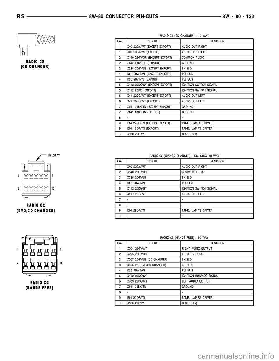
RADIO C2 (CD CHANGER) - 10 WAY
CAV CIRCUIT FUNCTION
1 X40 22GY/WT (EXCEPT EXPORT) AUDIO OUT RIGHT
1 X40 20GY/WT (EXPORT) AUDIO OUT RIGHT
2 X140 22GY/OR (EXCEPT EXPORT) COMMON AUDIO
2 Z140 18BK/OR (EXPORT) GROUND
3 X235 20GY/LB (EXCEPT EXPORT) SHIELD
4 D25 20WT/VT (EXCEPT EXPORT) PCI BUS
4 D25 20VT/YL (EXPORT) PCI BUS
5 X112 20DG/GY (EXCEPT EXPORT) IGNITION SWITCH SIGNAL
5 X112 20RD (EXPORT) IGNITION SWITCH SIGNAL
6 X41 22DG/WT (EXCEPT EXPORT) AUDIO OUT LEFT
6 X41 20DG/WT (EXPORT) AUDIO OUT LEFT
7 Z141 20BK/TN (EXCEPT EXPORT) GROUND
7 Z141 18BK/TN (EXPORT) GROUND
8- -
9 E14 22OR/TN (EXCEPT EXPORT) PANEL LAMPS DRIVER
9 E14 18OR/TN (EXPORT) PANEL LAMPS DRIVER
10 X160 20GY/YL FUSED B(+)
RADIO C2 (DVD/CD CHANGER) - DK. GRAY 10 WAY
CAV CIRCUIT FUNCTION
1 X40 22GY/WT AUDIO OUT RIGHT
2 X140 22GY/OR COMMON AUDIO
3 X235 20GY/LB SHIELD
4 D25 20WT/VT PCI BUS
5 X112 20DG/GY IGNITION SWITCH SIGNAL
6 X41 22DG/WT AUDIO OUT LEFT
7- -
8- -
9 E14 22OR/TN PANEL LAMPS DRIVER
10 - -
RADIO C2 (HANDS FREE) - 10 WAY
CAV CIRCUIT FUNCTION
1 X704 22GY/WT RIGHT AUDIO OUTPUT
2 X795 22GY/OR AUDIO GROUND
3 X207 20GY/LB (CD CHANGER) SHIELD
3 X955 22 (DVD/CD CHANGER) SHIELD
4 D25 20WT/VT PCI BUS
5 X112 20DG/GY IGNITION RUN/ACC SIGNAL
6 X703 22DG/WT LEFT AUDIO OUTPUT
7 Z141 20BK/TN GROUND
8- -
9 E14 22OR/TN PANEL LAMPS DRIVER
10 X160 20GY/YL FUSED B(+)
RS8W-80 CONNECTOR PIN-OUTS8W - 80 - 123
Page 1103 of 2339

RIGHT REAR LAMP ASSEMBLY - BLACK 6 WAY
CAV CIRCUIT FUNCTION
1 L62 18WT/BR (EXCEPT EXPORT) RIGHT REAR TURN SIGNAL DRIVER
1 Z362 18BK/BR (EXPORT) GROUND
2 L62 18WT/BR (EXPORT) RIGHT REAR TURN SIGNAL DRIVER
3 L50 18WT/TN (DIESEL) PRIMARY BRAKE SWITCH SIGNAL
3 L78 18WT/OR (EXCEPT EXPORT/EX-
CEPT TRAILER TOW)FUSED PARK LAMP RELAY OUTPUT (RIGHT)
3 L50 18WT/TN (GAS EXPORT) BRAKE LAMP SWITCH OUTPUT
3 L78 18WT/TN (TRAILER TOW) FUSED PARK LAMP RELAY OUTPUT (RIGHT)
4 L1 18WT/LG (EXCEPT TRAILER TOW) BACK-UP LAMP FEED
4 L1 18 WT/PK (TRAILER TOW) BACK-UP LAMP FEED
5 Z362 18BK/BR (EXCEPT EXPORT/EX-
CEPT TRAILER TOW)GROUND
5 L38 20WT/YL (EXPORT) REAR FOG LAMP SWITCH OUTPUT
5 Z362 18BR/OR (TRAILER TOW) GROUND
6 L78 18WT/OR (EXPORT) FUSED PARK LAMP RELAY OUTPUT (RIGHT)
RIGHT REAR PILLAR SPEAKER (HIGHLINE AUDIO) - BLACK 2 WAY
CAV CIRCUIT FUNCTION
1 X212 18GY/DB (EXCEPT EXPORT) AMPLIFIED RIGHT REAR TWEETER (-)
1 X212 20GY/DB (EXPORT) AMPLIFIED RIGHT REAR TWEETER (-)
2 X282 18GY/TN (EXCEPT EXPORT) AMPLIFIED RIGHT REAR TWEETER (+)
2 X282 20GY/TN (EXPORT) AMPLIFIED RIGHT REAR TWEETER (+)
RIGHT REAR READING LAMP (LUXURY) - GRAY 3 WAY
CAV CIRCUIT FUNCTION
1 M22 20YL/OR COURTESY LAMPS DRIVER
2 Z327 20BK/OR GROUND
3 M27 20YL/LB READING LAMPS DRIVER
RIGHT REAR SPEAKER-3WAY
CAV CIRCUIT FUNCTION
1 X296 18DG/GY (HIGHLINE EXCEPT
EXPORT)AMPLIFIED RIGHT REAR SPEAKER (-)
1 X296 20DG/GY (HIGHLINE EXPORT) AMPLIFIED RIGHT REAR SPEAKER (-)
1 X58 20GY/OR (LOWLINE) RIGHT REAR SPEAKER (-)
2- -
3 X206 18GY/DB (HIGHLINE EXCEPT
EXPORTAMPLIFIED RIGHT REAR SPEAKER (+)
3 X206 20GY/DB (HIGHLINE EXPORT) AMPLIFIED RIGHT REAR SPEAKER (+)
3 X52 20GY/DB (LOWLINE) RIGHT REAR SPEAKER (+)
8W - 80 - 134 8W-80 CONNECTOR PIN-OUTSRS
Page 1120 of 2339

CONNECTOR NAME/NUMBER COLOR LOCATION FIG.
Left Full Open Switch (Power
Sliding Door)BK Left Sliding Door N/S
Left Headlamp Caravan/Voyager
(Except Export)BK At Lamp 1
Left Headlamp (Town & Country) GN At Lamp 1
Left Headlamp Leveling Motor
(Export)WT At Motor N/S
Left High Beam Lamp (Export) BK At Lamp N/S
Left Instrument Panel Speaker WT At Speaker 20, 21, 27
Left Liftgate Flood Lamp (Power
Liftgate)GY At Lamp 49
Left Low Beam Lamp (Export) BK At Lamp N/S
Left Mid Reading Lamp
(Premium/Luxury)GY At Lamp N/S
Left Park Lamp (Export) BK At Lamp NS
Left Power Mirror BK At Mirror 27
Left Rear Lamp Assembly BK At Lamp 47
Left Rear Pillar Speaker (Highline
Audio)BK Left of Liftgate 47
Left Rear Reading Lamp (Luxury) GY At Lamp N/S
Left Rear Speaker (Highline) BK/RD At Speaker 47
Left Rear Speaker (Lowline) At Speaker N/S
Left Rear Vent Motor NAT At Motor 46, 47
Left Rear Wheel Speed Sensor BK Center Rear of Floor Pan 47
Left Remote Radio Switch BK Steering Wheel N/S
Left Repeater Lamp (Export) GY Left Front Fender 4, 36
Left Side Impact Sensor 1 DKGY Left B Pillar 40
Left Side Impact Sensor 2 Left Sliding Door N/S
Left Side Impact Sensor 3 BK Left Quarter Panel 47
Left Sliding Door Control Module
C1BK Left Sliding Door N/S
Left Sliding Door Control Module
C2Left Sliding Door N/S
Left Sliding Door Latch Sensing
SwitchBK Left Sliding Door N/S
Left Sliding Door Lock Motor BK Left Sliding Door N/S
Left Sliding Door Lock Motor/Ajar
Switch (Manual Sliding Door)BK Left Sliding Door N/S
Left Sliding Door Motor BK Left Sliding Door N/S
Left Speed Control Switch WT Steering Wheel N/S
Left Turn Signal Lamp (Export) OR AT Lamp N/S
Left Visor/Vanity Lamp BK At Lamp N/S
License Lamp DKGY At Lamp 49
Lift Pump Motor (Diesel) BK Left Rear Engine Compartment N/S
RS8W-91 CONNECTOR/GROUND/SPLICE LOCATION8W-91-7
CONNECTOR/GROUND/SPLICE LOCATION (Continued)
Page 1124 of 2339

CONNECTOR NAME/NUMBER COLOR LOCATION FIG.
Right Front Door Ajar Switch
(Base)BK At B Pillar N/S
Right Front Door Lock Motor/Ajar
Switch (Except Base)BK Right Front Door 44
Right Front Impact Sensor BK Near T/O for C303 N/S
Right Front Park/Turn Signal
Lamp (Except Export)BK At Lamp 1, 3
Right Front Wheel Speed Sensor GY Right Fender Side Shield 3,10, 16, 17
Right Full Open Switch (Power
Sliding Door)BK Right Sliding Door 45
Right Headlamp (Caravan/
Voyager Except Export)BK At Lamp 1, 3
Right Headlamp Leveling Motor
(Export)WT At Right Headlamp N/S
Right High Beam Lamp (Export) BK At Right Headlamp N/S
Right Instrument Panel Speaker WT At Speaker 20, 23, 24
Right Liftgate Flood Lamp (Power
Liftgate)GY At Lamp 49
Right Low Beam Lamp (Export) BK At Right Headlamp N/S
Right Mid Reading Lamp
(Premium/ Luxury)GY At Lamp N/S
Right Park Lamp (Export) BK AT Lamp N/S
Right Power Mirror BK At Mirror 20, 24, 28
Right Rear Lamp Assembly BK At Lamp 48
Right Rear Pillar Speaker
(Highline Audio)BK At Speaker 48
Right Rear Reading Lamp
(Luxury)GY At Lamp N/S
Right Rear Speaker) At Speaker 48
Right Rear Vent Motor NAT At Motor 48
Right Rear Wheel Speed Sensor BK Right Rear of Floor Pan 48
Right Remote Radio Switch BK At Steering Wheel N/S
Right Repeater Lamp (Export) GY Right Front Fender 39
Right Side Impact Sensor 1 Right B Pillar 39
Right Side Impact Sensor 2 Right Sliding Door 32
Right Side Impact Sensor 3 BK Right Quarter Panel 48
Right Sliding Door Control
Module C1BK Right Sliding Door 45, 46
Right Sliding Door Control
Module C2Right Sliding Door 45, 46
Right Sliding Door Latch Sensing
SwitchBK Right Sliding Door 45
Right Sliding Door Lock Motor BK Right Sliding Door 45
Right Sliding Door Lock
Motor/Ajar Switch (Manual Sliding
Door)BK Right Sliding Door N/S
RS8W-91 CONNECTOR/GROUND/SPLICE LOCATION8W-91-11
CONNECTOR/GROUND/SPLICE LOCATION (Continued)
Page 1129 of 2339
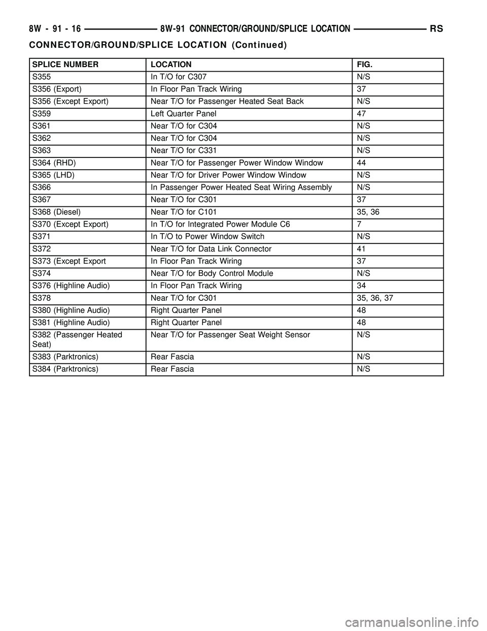
SPLICE NUMBER LOCATION FIG.
S355 In T/O for C307 N/S
S356 (Export) In Floor Pan Track Wiring 37
S356 (Except Export) Near T/O for Passenger Heated Seat Back N/S
S359 Left Quarter Panel 47
S361 Near T/O for C304 N/S
S362 Near T/O for C304 N/S
S363 Near T/O for C331 N/S
S364 (RHD) Near T/O for Passenger Power Window Window 44
S365 (LHD) Near T/O for Driver Power Window Window N/S
S366 In Passenger Power Heated Seat Wiring Assembly N/S
S367 Near T/O for C301 37
S368 (Diesel) Near T/O for C101 35, 36
S370 (Except Export) In T/O for Integrated Power Module C6 7
S371 In T/O to Power Window Switch N/S
S372 Near T/O for Data Link Connector 41
S373 (Except Export In Floor Pan Track Wiring 37
S374 Near T/O for Body Control Module N/S
S376 (Highline Audio) In Floor Pan Track Wiring 34
S378 Near T/O for C301 35, 36, 37
S380 (Highline Audio) Right Quarter Panel 48
S381 (Highline Audio) Right Quarter Panel 48
S382 (Passenger Heated
Seat)Near T/O for Passenger Seat Weight Sensor N/S
S383 (Parktronics) Rear Fascia N/S
S384 (Parktronics) Rear Fascia N/S
8W - 91 - 16 8W-91 CONNECTOR/GROUND/SPLICE LOCATIONRS
CONNECTOR/GROUND/SPLICE LOCATION (Continued)
Page 1418 of 2339
WARNING: THE AIR BAG SYSTEM IS A SENSITIVE,
COMPLEX ELECTRO-MECHANICAL UNIT. BEFORE
ATTEMPTING TO DIAGNOSE, REMOVE OR INSTALL
THE AIR BAG SYSTEM COMPONENTS YOU MUST
FIRST DISCONNECT AND ISOLATE THE BATTERY
NEGATIVE (GROUND) CABLE. THEN WAIT TWO
MINUTES FOR THE SYSTEM CAPACITOR TO DIS-
CHARGE. FAILURE TO DO SO COULD RESULT IN
ACCIDENTAL DEPLOYMENT OF THE AIR BAG AND
POSSIBLE PERSONAL INJURY. THE FASTENERS,
SCREWS, AND BOLTS, ORIGINALLY USED FOR
THE AIR BAG COMPONENTS, HAVE SPECIAL
COATINGS AND ARE SPECIFICALLY DESIGNED
FOR THE AIR BAG SYSTEM. THEY MUST NEVER
BE REPLACED WITH ANY SUBSTITUTES. ANYTIME
A NEW FASTENER IS NEEDED, REPLACE WITH
THE CORRECT FASTENERS PROVIDED IN THE
SERVICE PACKAGE OR FASTENERS LISTED IN
THE PARTS BOOKS.
WARNING: SAFETY GOGGLES SHOULD BE WORN
AT ALL TIMES WHEN WORKING ON STEERING
COLUMNS.
CAUTION: Disconnect negative (ground) cable from
the battery before servicing any column compo-
nent.
CAUTION: Do not attempt to remove the pivot pins
to disassemble the tilting mechanism. Damage will
occur.
DIAGNOSIS AND TESTING - STEERING
COLUMN
For diagnosis of conditions relating to the steering
column, (Refer to 19 - STEERING - DIAGNOSIS
AND TESTING).
REMOVAL
NOTE: Before proceeding, (Refer to 19 - STEERING/
COLUMN - WARNING)(Refer to 8 - ELECTRICAL/RE-
STRAINTS/DRIVER AIRBAG - REMOVAL).
(1) Make sure the front wheels of the vehicle are
in the STRAIGHT AHEAD position before beginning
the column removal procedure.
(2) Disconnect and isolate the negative (ground)
cable from the battery. Wait at least two minutes for
the airbag system reserve capacitor to discharge
before beginning any steering column, instrument
panel, or airbag system/component service.WARNING: WHEN AN UNDEPLOYED AIRBAG IS TO
BE REMOVED FROM THE VEHICLE, FIRST DISCON-
NECT AND ISOLATE THE BATTERY NEGATIVE
(GROUND) CABLE. ALLOW THE AIRBAG SYSTEM
RESERVE CAPACITOR TO DISCHARGE FOR TWO
MINUTES BEFORE BEGINNING ANY AIRBAG SYS-
TEM OR COMPONENT SERVICE. PERSONAL
INJURY MAY RESULT IF THIS PROCEDURE IS NOT
FOLLOWED.
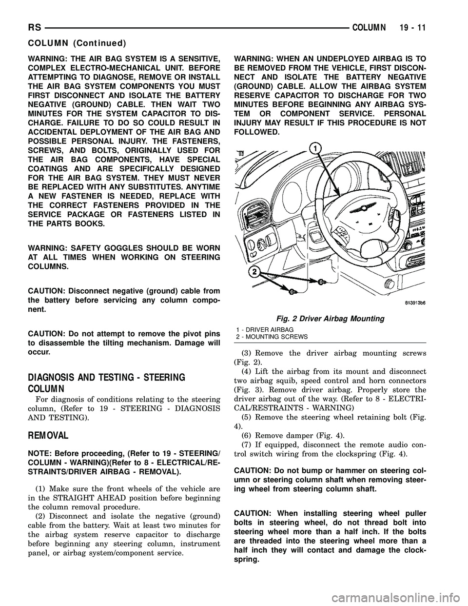
(3) Remove the driver airbag mounting screws
(Fig. 2).
(4) Lift the airbag from its mount and disconnect
two airbag squib, speed control and horn connectors
(Fig. 3). Remove driver airbag. Properly store the
driver airbag out of the way. (Refer to 8 - ELECTRI-
CAL/RESTRAINTS - WARNING)
(5) Remove the steering wheel retaining bolt (Fig.
4).
(6) Remove damper (Fig. 4).
(7) If equipped, disconnect the remote audio con-
trol switch wiring from the clockspring (Fig. 4).
CAUTION: Do not bump or hammer on steering col-
umn or steering column shaft when removing steer-
ing wheel from steering column shaft.
CAUTION: When installing steering wheel puller
bolts in steering wheel, do not thread bolt into
steering wheel more than a half inch. If the bolts
are threaded into the steering wheel more than a
half inch they will contact and damage the clock-
spring.
Fig. 2 Driver Airbag Mounting
1 - DRIVER AIRBAG
2 - MOUNTING SCREWS
RSCOLUMN19-11
COLUMN (Continued)
Page 1419 of 2339
(8) Remove the steering wheel using a standard
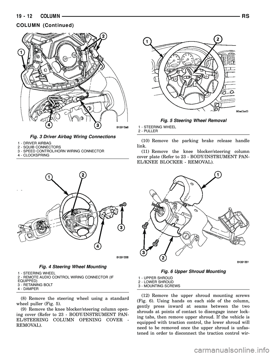
wheel puller (Fig. 5).
(9) Remove the knee blocker/steering column open-
ing cover (Refer to 23 - BODY/INSTRUMENT PAN-
EL/STEERING COLUMN OPENING COVER -
REMOVAL).(10) Remove the parking brake release handle
link.
(11) Remove the knee blocker/steering column
cover plate (Refer to 23 - BODY/INSTRUMENT PAN-
EL/KNEE BLOCKER - REMOVAL).
(12) Remove the upper shroud mounting screws
(Fig. 6). Using hands on each side of the column,
gently press inward at seams between the two
shrouds at points of contact to disengage inner lock-
ing tabs, then remove upper shroud. If the vehicle is
equipped with traction control, the lower shroud will
need to be removed once the upper shroud is unfas-
tened in order to disconnect the traction control wir-
Fig. 3 Driver Airbag Wiring Connections
1 - DRIVER AIRBAG
2 - SQUIB CONNECTORS
3 - SPEED CONTROL/HORN WIRING CONNECTOR
4 - CLOCKSPRING
Fig. 4 Steering Wheel Mounting
1 - STEERING WHEEL
2 - REMOTE AUDIO CONTROL WIRING CONNECTOR (IF
EQUIPPED)
3 - RETAINING BOLT
4 - DAMPER
Fig. 5 Steering Wheel Removal
1 - STEERING WHEEL
2 - PULLER
Fig. 6 Upper Shroud Mounting
1 - UPPER SHROUD
2 - LOWER SHROUD
3 - MOUNTING SCREWS
19 - 12 COLUMNRS
COLUMN (Continued)
Page 1424 of 2339
(19) Position the lower shroud on the column (Fig.
8). Install the lower shroud mounting screw. Tighten
the screw to 2 N´m (17 in. lbs.) torque.
(20) If equipped with adjustable pedals, Connect
the wiring connector for the switch (Fig. 7) to the col-
umn wiring harness.
(21) Position the upper shroud on top of the lower
shroud and snap it into place. Install the upper
shroud mounting screws (Fig. 6). Tighten the screws
to 2 N´m (17 in. lbs.) torque.
(22) Inspect shroud mating surfaces for excessive
gaps and correct as necessary.
(23) Install the cluster trim bezel (Refer to 23 -
BODY/INSTRUMENT PANEL/CLUSTER BEZEL -
INSTALLATION).
(24) Install the knee blocker/steering column cover
plate. (Refer to 23 - BODY/INSTRUMENT PANEL/
KNEE BLOCKER - INSTALLATION)
(25) Install the parking brake handle link.
(26) Install the knee blocker/steering column open-
ing cover. (Refer to 23 - BODY/INSTRUMENT PAN-
EL/STEERING COLUMN OPENING COVER -
INSTALLATION)
(27) Align the splines and install the steering
wheel on the steering column shaft(Refer to 19 -
STEERING/COLUMN/STEERING WHEEL -
INSTALLATION).
(28) Install the damper over the steering column
shaft (Fig. 4).
(29) Install the steering wheel retaining bolt (Fig.
4). Tighten the bolt to 61 N´m (45 ft. lbs.) torque.
(30) If the steering wheel is equipped with remote
audio controls, connect the wiring connector to the
clockspring (Fig. 4).
(31) Connect the two squib connectors to the
driver airbag (Fig. 3). The connectors are color coded
to avoid connector mix-up.
(32) Connect the speed control and horn connector
to the clockspring (Fig. 3).
(33) Install the airbag to the steering wheel.
Install the driver airbag mounting screws (Fig. 2).
Tighten screws to 10 N´m (90 in. lbs.) torque.
(34) Connect the battery negative (ground) cable to
battery post following special Diagnosis And Testing
procedure. (Refer to 8 - ELECTRICAL/RESTRAINTS
- DIAGNOSIS AND TESTING)
(35) Check operation of all steering column
mounted components.
(36) Road test vehicle to ensure proper operation
of steering.SPECIFICATIONS
COLUMN FASTENER TORQUE
DESCRIPTION N´mFt.
Lbs.In.
Lbs.
Driver Airbag Mounting Screws 10 Ð 90
Multi-Function Switch Mounting
Housing Set-Screw14 Ð 124
Shroud Attaching Screws - Fixed 3 Ð 23
Shroud Attaching Screws -
Lower/Upper2Ð17
SKIM Attaching Screw 4 Ð 30
Steering Column Coupling Pinch
Bolt28 Ð 250
Steering Column Mounting Nuts 12 Ð 105
Steering Wheel Retaining Bolt 61 45 Ð
IGNITION SWITCH
REMOVAL
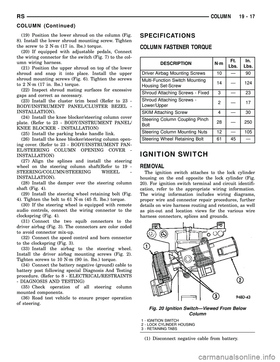
The ignition switch attaches to the lock cylinder
housing on the end opposite the lock cylinder (Fig.
20). For ignition switch terminal and circuit identifi-
cation, refer to the appropriate wiring information.
The wiring information includes wiring diagrams,
proper wire and connector repair procedures, further
details on wire harness routing and retention, as well
as pin-out and location views for the various wire
harness connectors, splices and grounds.
(1) Disconnect negative cable from battery.
Fig. 20 Ignition SwitchÐViewed From Below
Column
1 - IGNITION SWITCH
2 - LOCK CYLINDER HOUSING
3 - RETAINING TABS
RSCOLUMN19-17
COLUMN (Continued)
Page 1431 of 2339

(2) Remove the driver airbag mounting screws
(Fig. 40).
(3) Lift the airbag from its mount and disconnect
two airbag squib, speed control and horn connectors
(Fig. 41). Remove driver airbag. Properly store the
driver airbag out of the way. (Refer to 8 - ELECTRI-
CAL/RESTRAINTS - WARNING)(4) Remove the steering wheel retaining bolt (Fig.
42).
(5) Remove damper (Fig. 42).
(6) If equipped, disconnect the remote audio con-
trol switch wiring from the clockspring (Fig. 42).
CAUTION: Do not bump or hammer on steering col-
umn or steering column shaft when removing steer-
ing wheel from steering column shaft.
CAUTION: When installing steering wheel puller
bolts in steering wheel, do not thread bolt into
steering wheel more than a half inch. If the bolts
are threaded into the steering wheel more than a
half inch they will contact and damage the clock-
spring.
(7) While holding the steering wheel firmly in the
straight-aheadposition, remove the steering wheel
from steering column shaft using a steering wheel
puller (Fig. 43).
(8) Remove the puller from the steering wheel.
(9) If the remote audio switches need removed
from the steering wheel, (Refer to 8 - ELECTRICAL/
AUDIO/REMOTE SWITCHES - REMOVAL).
INSTALLATION
(1) If the remote radio switches need to be
installed on the steering wheel, (Refer to 8 - ELEC-
TRICAL/AUDIO/REMOTE SWITCHES - INSTALLA-
TION).
CAUTION: Do not force steering wheel onto steer-
ing column shaft by driving it on. Pull steering
wheel down onto shaft using only the steering
wheel retaining nut.
Fig. 41 Driver Airbag Wiring Connections
1 - DRIVER AIRBAG
2 - SQUIB CONNECTORS
3 - SPEED CONTROL/HORN WIRING CONNECTOR
4 - CLOCKSPRING
Fig. 42 Steering Wheel Mounting
1 - STEERING WHEEL
2 - REMOTE AUDIO CONTROL WIRING CONNECTOR (IF
EQUIPPED)
3 - RETAINING BOLT
4 - DAMPER
Fig. 43 Steering Wheel Removal
1 - STEERING WHEEL
2 - PULLER
19 - 24 COLUMNRS
STEERING WHEEL (Continued)
Page 1432 of 2339

(2) Feed and route wiring from clockspring
through upper access hole in steering wheel.
(3) Align master serrations in steering wheel with
omitted spline on steering column shaft (at 12 o'clock
position). Slide the steering wheel onto the steering
column shaft by hand (Fig. 42). Use care not to pinch
any wiring.
NOTE: Before installing the damper on the steering
wheel, inspect the damper to ensure the rubber iso-
lator on the damper is not deteriorated or damaged.
If the damper is installed with a damaged isolator, a
buzz, squeak or rattle condition may develop.
(4) Install the damper on the steering wheel (Fig.
42).
(5) Install the steering wheel retaining bolt.
Tighten the steering wheel retaining bolt to 61 N´m
(45 ft. lbs.) torque.(6) If the steering wheel is equipped with remote
audio controls, connect the wiring connector to the
clockspring (Fig. 42).
(7) Connect the airbag squib wiring connectors to
the airbag and the horn and speed control switch
connector to the clockspring (Fig. 41).
(8) Install the driver airbag in the steering wheel
(Fig. 40). Install and tighten the airbag attaching
screws to 10 N´m (90 in. lbs.) torque.
(9) Connect the battery negative (ground) cable to
battery post following special Diagnosis And Testing
procedure. (Refer to 8 - ELECTRICAL/RESTRAINTS
- DIAGNOSIS AND TESTING)
(10) Check operation of all steering wheel mounted
components.
(11) Road test vehicle to ensure proper operation of
steering.
RSCOLUMN19-25
STEERING WHEEL (Continued)