wiring CITROEN CX 1988 Service Manual
[x] Cancel search | Manufacturer: CITROEN, Model Year: 1988, Model line: CX, Model: CITROEN CX 1988Pages: 648, PDF Size: 95.8 MB
Page 91 of 648

REMOVING AND REFITTING
THE ENGINE/GEARBOX ASSEMBLY
- 2.5 LITRE CX WITH PETROL INJECTION -
REMOVAL
Support the car on stands horizontally, Fig. I using
the three stands 6602-T, in order to facilitate the
removal of the power unit assembly and to reposition
it more easily on the stands.
Depressurize the hydraulic system.
Drain the brake accumulator.
Set the height control to the “low” position
Remove:
- the battery,
- the bonnet,
- the front wheel,
- the spare wheel
- the protection plate located under the spare wheel,
Drain the cooling circuit via the drain hose of the
radiator.
Take off the crankcase drain plug (I 1, Fig. II.
Remove the drive-shafts:
(Refer to Op @ MA.372. l/l)
Uncouple: hoses (6) and (71, Fig. IV (protecting the
alternator from water entry at “a”).
Disconnect the engine cooling fan thermal switch.
Remove the engine heat sink.
Extract, Fig. Ill:
- the screws that secure horn (2) support, passing
through the wheelarch,
- the wheelarch lining. Disconnect:
- wiring harnesses (3) from the battery positive lead,
Fig. Ill,
- the ground cable from the gearbox,
- the wiring harness from the reversing lamp switch.
Remove, Fig. Ill:
- the pressure regulator accumulator,
- pipe (4) between pressure regulator and brake accu-
mulator.
Vehicle with air conditioning option:
- the belt protective cover,
- the air conditioning compressor drive belt
Uncouple:
- the air intake casing position accelerator cable,
- the high pressure pump rubber suction pipe,
- the high pressure pump outlet pipe (5) and its attach-
ment, Fig. Ill.
Disconnect: Fig. V
- the throttle spindle switch (IO),
- knock sensor (14).
Uncouple: Fig. V
- pressure sensor pipe(91,
- supplementary air pipe (I I),
- cylinderhead cover pipe (I 21,
- breather pipe (8).
Remove suction pipe (I 3) situated between the flow-
meter and the turbocharger or between the flowme-
ter and the inlet manifold.
Page 259 of 648
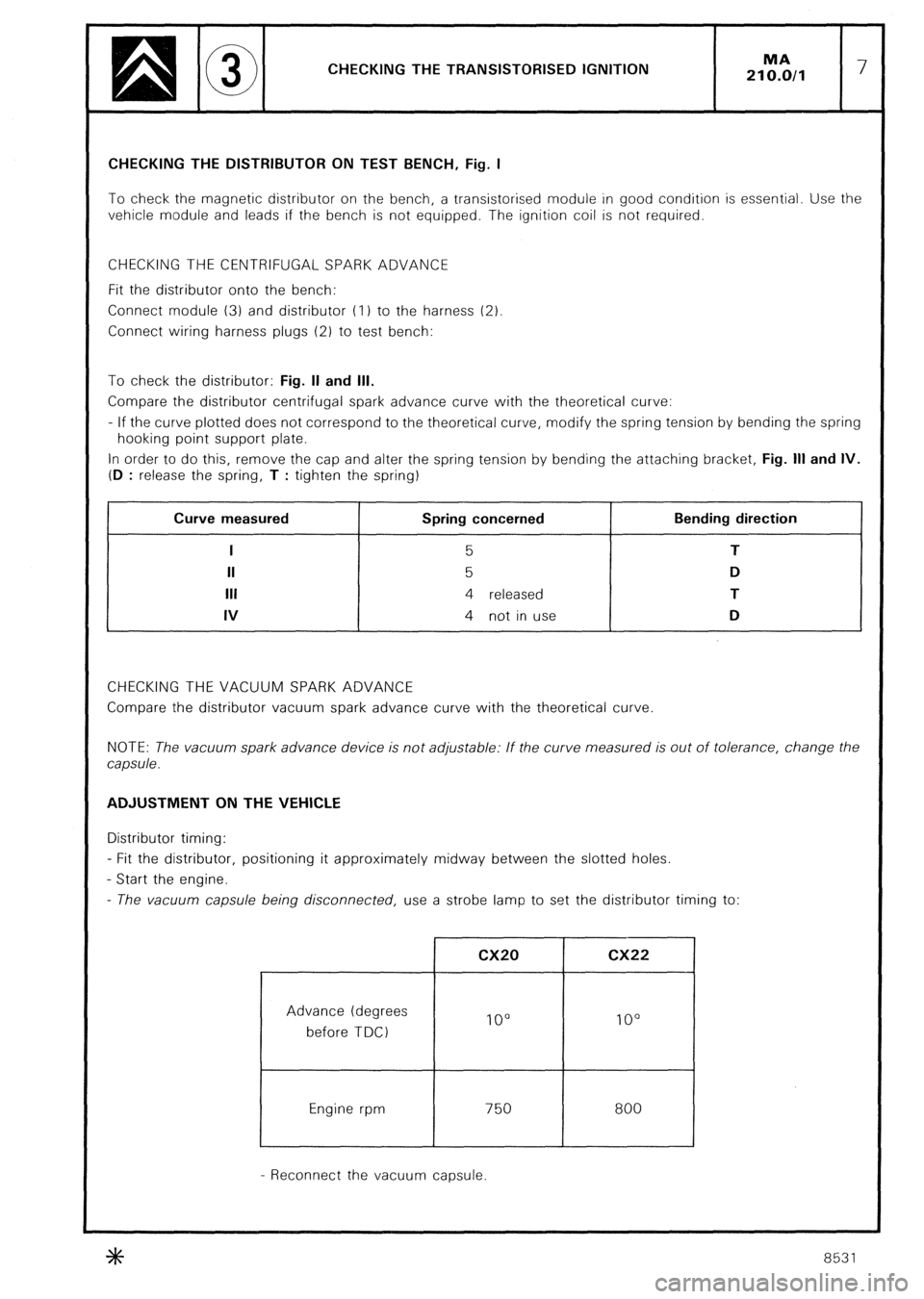
CHECKING THE TRANSISTORISED IGNITION MA
210.0/l 7 CHECKING THE DISTRIBUTOR ON TEST BENCH, Fig. I
To check the magnetic distributor on the bench, a transistorised module in good condition is essential. Use the
vehicle module and leads if the bench is not equipped. The ignition coil is not required.
CHECKING THE CENTRIFUGAL SPARK ADVANCE
Fit the distributor onto the bench:
Connect module (3) and distributor (I 1 to the harness (2)
Connect wiring harness plugs (2) to test bench:
To check the distributor: Fig. II and Ill.
Compare the distributor centrifugal spark advance curve with the theoretical curve:
- If the curve plotted does not correspond to the theoretical curve, modify the spring tension by bending the spring
hooking point support plate.
In order to do this, remove the cap and alter the spring tension by bending the attaching bracket, Fig. Ill and IV.
(D
: release the spring, T : tighten the spring) , Curve measured
I
II
Ill
IV Spring concerned
5
5
4 released
4 not in use Bending direction
T
D
T
D
CHECKING THE VACUUM SPARK ADVANCE
Compare the distributor vacuum spark advance curve with the theoretical curve
NOTE: The vacuum spark advance device is not adjustable: If the curve measured is out of tolerance, change the
capsule. ADJUSTMENT ON THE VEHICLE
Distributor timing:
- Fit the distributor, positioning it approximately midway between the slotted holes.
- Start the engine.
- The vacuum capsule being disconnected, use a strobe lamp to set the distributor timing to:
Advance (degrees
before TDC)
Engine rpm cx20 cx22
IO0 lo0
750
I 800
- Reconnect the vacuum capsule.
8531
Page 378 of 648
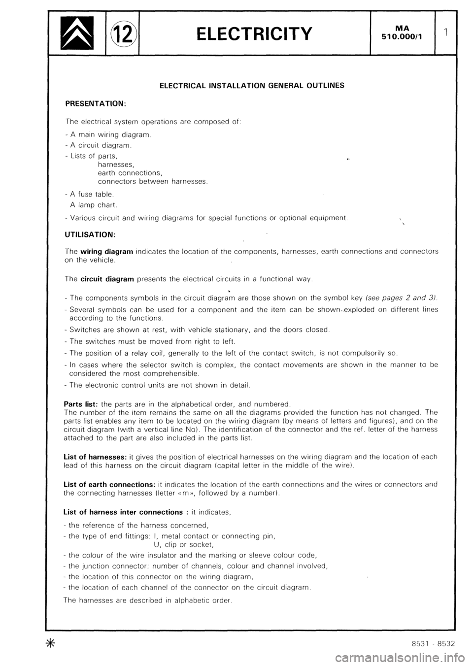
ELECTRICITY
MA 510.00011 1
ELECTRICAL INSTALLATION GENERAL OUTLINES
PRESENTATION:
The electrical system operations are composed of:
- A main wiring diagram.
- A circuit diagram.
- Lists of parts,
harnesses,
earth connections,
connectors between harnesses.
- A fuse table.
A lamp chart.
- Various circuit and wiring diagrams for special functions or optional equipment.
I_
UTILISATION:
The wiring diagram indicates the location of the components, harnesses, earth connections and connectors
on the vehicle.
The circuit diagram presents the electrical circuits in a functional way.
- The components symbols in the circuit diagra*m are those shown on the symbol key (see pages 2 and 31.
- Several symbols can be used for a component and the item can be shownC.exploded on different lines
according to the functions.
- Switches are shown at rest, with vehicle stationary, and the doors closed.
- The switches must be moved from right to left.
- The position of a relay coil, generally to the left of the contact switch, is not compulsorily so.
- In cases where the selector switch is complex, the contact movements are shown in the manner to be
considered the most comprehensible.
- The electronic control units are not shown in detail.
Parts list: the parts are in the alphabetical order, and numbered.
The number of the item remains the same on all the diagrams provided the functron has not changed. The
parts list enables any item to be located on the wiring diagram (by means of letters and figures), and on the
circuit diagram (with a vertical line No). The identification of the connector and the ref. letter of the harness
attached to the part are also included in the parts list.
List of harnesses: it gives the position of electrical harnesses on the wiring diagram and the location of each
lead of this harness on the circuit diagram (capital letter in the middle of the wire).
List of earth connections: it indicates the location of the earth connections and the wires or connectors and
the connecting harnesses (letter CC m )), followed by a number).
List of harness inter connections : it indicates,
- the reference of the harness concerned,
- the type of end fittings: I, metal contact or connecting pin,
U, clip or socket,
- the colour of the wire insulator and the marking or sleeve colour code,
- the junction connector: number of channels, colour and channel involved,
- the location of this connector on the wiring diagram,
- the location of each channel of the connector on the circuit diagram.
The harnesses are described in alphabetic order.
8531 8532
Page 379 of 648
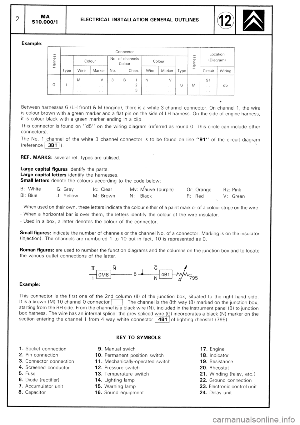
2 51 O%O,l ELECTRICAL INSTALLATION GENERAL OUTLINES
Example:
Connector
cc
t: Locatlori
E
Colour No of channels
Colour a,
(DIagramI
5 Colour :
L
Type Wire 2
Marker No Chan WlrC Marker Type Circuit Wlrlng
M V 3 B 1 N v
91
G I 2 U M d5
3
Between harnesses G (LIH front) & M (engine), there is a white 3 channel connector. On channel 1, the wire
is colour brown with a green marker and a flat pin on the side of LH harness. On the side of engine harness,
it is colour black with a green marker ending in a clip.
This connector is found on “d5” on the wiring diagram (referred as round 0. This circle can include other
connectors).
The No. 1 channel of the white 3 channel connector is to be found on line “91” of the circuit diagram
(reference /3B1/ 1. I
REF. MARKS: several ref. types are utilised.
Large capital figures identify the parts,
Large capital letters identify the harnesses.
Small letters denote the colours according to the code below:
B: White G: Grey Ic: Clear Mv: Gauve (purple) Or: Orange Rr: Pink
BI: Blue J: Yellow M: Brown N: Black R: Red V: Green
1.
- When used on their own, these letters indicate the colour either of a paint mark or of a colour stripe on the wire.
- When a horizontal bar is over them, the letters identify the colour of the wire insulator.
- Used in a box, a letter denotes the colour of the connector.
Small figures: indicate the number of channels or the channel No. of a connector. Marking IS on the insulator
(injection). The channels are numbered 1 to 10 but in fact, 10 is represented as 0.
Roman figures: are used to number the function diagrams and the columns on the junction box and to locate
the various outlet connections of the latter.
$ii-f--B i &Bl/+&-
795
Example:
This connector is the first one of the 2nd column (II) of the junction box, situated to the right hand side.
It is a brown (Ml IO channel 0 connector i-1 The channel is the 8th way (8) marked on the junction box,
starting from the RH side. From the channel is a black wire (N), included in the instrument panel (B) to junction
box harness. The wire has an internal splice: the grey spliced wire (G) incorporates a black (N) marker on the
section entering the channel 1 from 4 way white connector m of lighting rheostat (795).
KEY TO SYMBOLS
1. Socket connection 9. Manual swich 17. Engine
2. Pin connection IO. Permanent position switch 18. Indicator
3. Connector connection 11. Mechanically-operated switch 19. Resistance
4. Screened conductor 12. Pressure switch 20. Rheostat
5. Fuse 13. Temperature switch 21. Winding (ielay, etc.)
6. Diode (rectifier) 14. Lighting lamp 22. Ground connection
7. Accumulator unit 15. Warning lamp 23. Electronic control unit
8. Capacitor 16. Sound equipment 24. Delay unit
Page 392 of 648
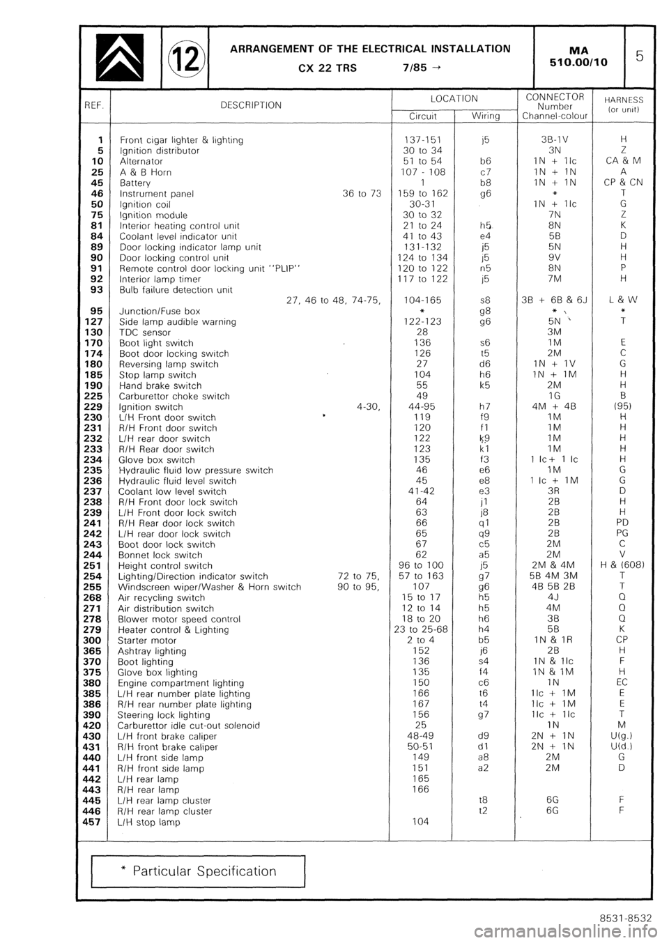
ARRANGEMENT OF THE ELECTRICAL INSTALLATION
q @ CX22TRS 7/85-t 1 MA 5 510.00110
3EF. DESCRIPTION LOCATION
Circuit Wiring CONNECTOR
Number HARNESS
Channel-colour (or urilt)
1 Front cigar ljghter & lighting 137-151
i5 38-l v H
5 Ignition distributor 30 to 34 3N 2
10 Alternator 51 to 54 b6 IN + Ilc CA & M
25 A & B Horn 107 - 108 c7 1N + 1N A
45 Battery 1
b8 IN + IN CP & CN
46 Instrument panel 36 to 73 159 to 162 g6 * T
50 Ignition coil 30-3 1 IN + Ilc G
75 Ignition module 30 to 32 7N Z
81 Interior heating control unit 21 to 24 h5 8N K
84 Coolant level indicator unit 41 to 43 e4 5B D
89 Door locking indicator lamp unit 131-132
i5 5N H
90 Door locking control unit 124 to 134 15 9v H
91 Remote control door locking unit “PLIP” 120 to 122 n5 8N P
92 Interior lamp timer 117 to 122 15 7M H
93 Bulb failure detection unit
27, 46 to 48, 74-75, 104-I 65 S8 38 + 68 & 6J L & w
95 Junction/Fuse box
127 Side lamp audible warning 1222123 g8
g6 5+N‘” ;
130 TDC sensor 28 3M
170 Boot light switch 136 s6 IM E
174 Boot door locking switch 126 t5 2M C
180 Reversing lamp switch 27 d6 1N + 1V G
185 Stop lamp switch 104 h6 IN + IM H
190 Hand brake switch 55 k5 2M H
!25 Carburettor choke switch 49 IG B
!29 Ignition switch 4-30, 44-95 h7 4M + 48 (95)
!30 L/H Front door switch *
119 f9 IM H
!31 R/H Front door switch 120 fl 1M H
!32 L/H rear door switch 122
k9 IM H
!33 R/H Rear door switch 123 kl IM H
!34 Glove box switch 135 f3 1 Ic+ 1 Ic H
!35 Hydraulic fluid low pressure switch 46 e6 IM G
!36 Hydraulic fluid level switch 45 e8 1 Ic + IM G
!37 Coolant low level switch 41-42 e3 3R D
!38 R/H Front door lock switch 64
jl 28 H
!39 L/H Front door lock switch 63 P
28 H
!41 R/H Rear door lock switch 66 (71 28 PD !42 L/H rear door lock switch 65 qg 28 PG
!43 Boot door lock switch 67 c5 2M C
!44 Bonnet lock switch 62 a5 2M V
!51 Height control switch 96 to 100
j5 2M & 4M H & (608) !54 Lighting/Direction indicator switch 72 to 75. 57 to 163 97 58 4M 3M T
!55 Windscreen wiper/Washer & Horn switch 90 to 95, 107 g6 48 5B 28 T
!68 Air recycling switch 15 to 17
h5 4J Q
!71 Air distribution switch 12 to 14 h5 4M Q !78 Blower motor speed control 18 to 20 h6 38 Q
!79 Heater control & Lighting 23 to 25-68 h4 58 K
100 Starter motor 2 to 4 b5 IN & IR CP 165 Ashtray lighting 152 if5 2B H
I70 Boot lighting 136 s4 1N & llc F
I75 Glove box lighting 135 f4 IN & 1M H I80 Engine compartment lighting 150 c6 IN EC
I85 L/H rear number plate lighting 166 t6 Ilc + IM E 186 R/H rear number plate lighting 167 t4 Ilc + IM E
190 Steering lock lighting 156 97 Ilc + IIC T
L20 Carburettor idle cut-out solenoid 25 IN M L30 L/H front brake caliper 48-49 d9 2N + IN U(g.) I31 R/H front brake caliper 50-51 dl 2N + IN U(d.!
L40 L/H front side lamp 149 a8 2M G
141 R/H front side lamp 151 a2 2M D 142 L/H rear lamp 165 L43 R/H rear lamp 166 I45 L/H rear lamp cluster t8 6G F
146 R/H rear lamp cluster t2 6G F
157 L/H stop lamp 104
* Particular Specification
8531-8532
Page 393 of 648
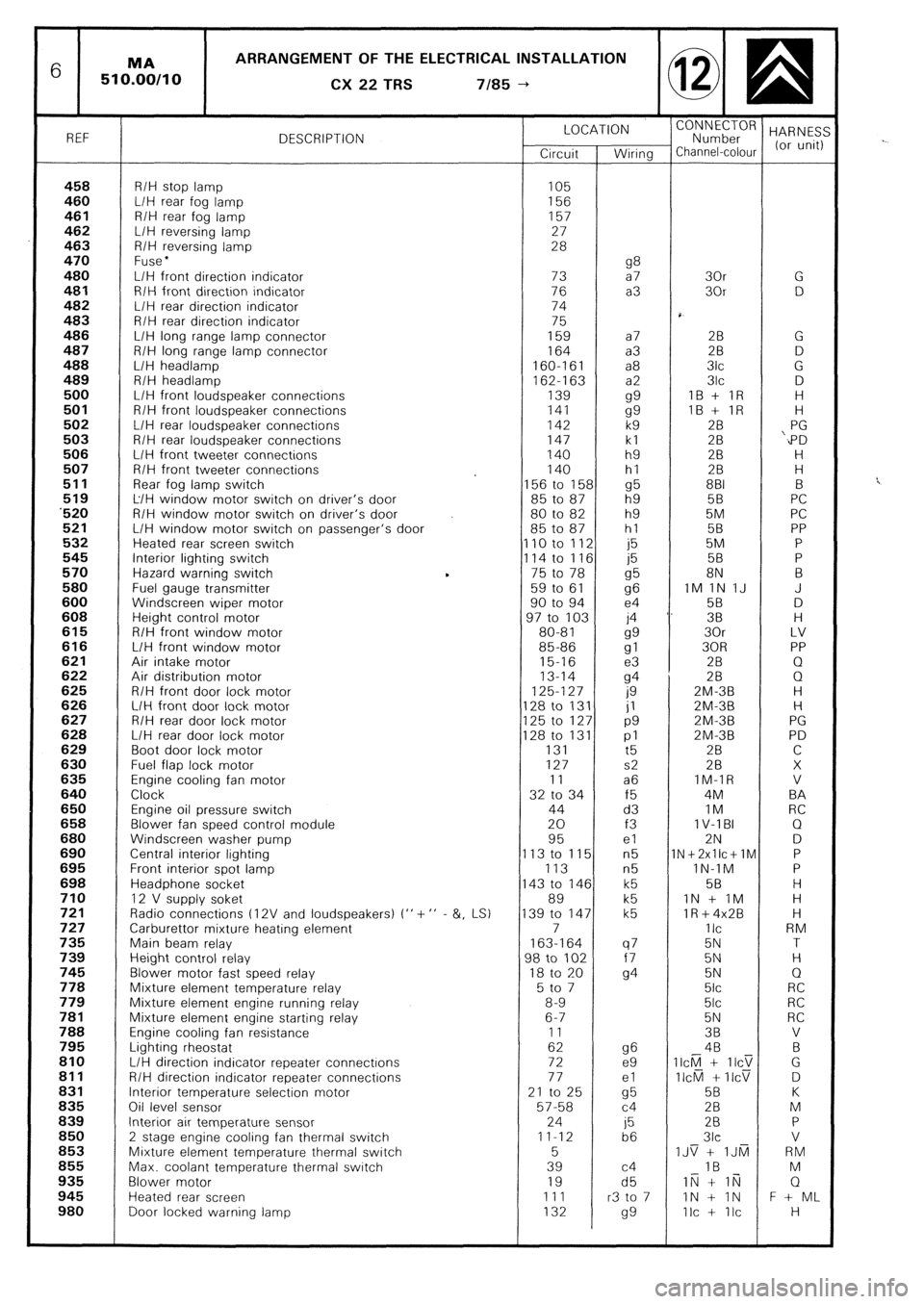
6 ARRANGEMENT OF THE ELECTRICAL INSTALLATION
CX
22 TRS 7185 --)
REF DESCRIPTION LOCATION
“;;;;;roR HARNES:
Circuit Wiring Channel-colour (or unit)
458 R/H stop lamp 105 460 L/H rear fog lamp 156 461 R/H rear fog lamp 157
462 L/H reversing lamp 27
463 R/H reversing lamp 28
470 Fuse l 480 g8 L/H front direction indicator 73 a7 30r G 481 R/H front direction indicator 76 a3 30r D 482 L/H rear direction indicator 74
483 R/H rear direction indicator 75
486 L/H long range lamp connector 159 a7 28 G 487 R/H long range lamp connector 164 a3 2B D 488 L/H headlamp 160-161 a8 3lc G
489 R/H headlamp
162-l 63 a2 3lc D 500 L/H front loudspeaker connections 139
gg IB + IR H 501 R/H front loudspeaker connections 141
gg IB + IR H 502 L/H rear loudspeaker connections 142 k9 28 PG 503 R/H rear loudspeaker connections 147 kl 28 ‘,PD 506 L/H front tweeter connections 140 h9 2B H 507 R/H front tweeter connections 140 hl 28 H
511 Rear fog lamp switch 156 to 158 g5 881 B 519 L/H window motor switch on driver’s door 85 to 87 h9 5B PC ‘520 R/H window motor switch on driver’s door 80 to 82 h9 5M PC 521 L/H window motor switch on passenger’s door 85 to 87 hl 58 PP 532 Heated rear screen switch 110 to 112 j5 5M P 545 Interior lighting switch
114 to 116 j5 58 P 570 Hazard warning switch 75 to 78
g5 8N B 580 Fuel gauge transmitter 59 to 61
96 IM 1N IJ J 600 Windscreen wiper motor 90 to 94 e4 58 D 608 Height control motor 97 to 103 j4 ‘. 38 H 615 R/H front window motor 80-81
gg 30r LV 616 L/H front window motor 85-86
gl 30R PP 621 Air intake motor 15-16 e3 2B Q 622 Air distribution motor 13-14
94 28 0 625 R/H front door lock motor 125-127
0 ZM-3B H 626 L/H front door lock motor 128 to 131 jl ZM-3B H 627 R/H rear door lock motor 125 to 127 p9 2M-3B PG 628 L/H rear door lock motor 128 to 131 pl 2M-3B PD 629 Boot door lock motor 131
t5 2B C 630 Fuel flap lock motor 127 s2 28 X 635 Engine cooling fan motor 11 a6 IM-IR V 640 Clock 32 to 34 f5 4M BA 650 Engine oil pressure switch 44 d3 IM RC 658 Blower fan speed control module 20 f3 1 V-l BI Q 680 Windscreen washer pump 95 el 2N D 690 Central interior lighting 113 to 115 n5 1N+2xllc+lM P 695 Front interior spot lamp 113 n5 lN-1M P 698 Headphone socket 143 to 146 k5 58 H 710 12 V supply soket 89 k5 IN + IM H 721 Radio connections t 12V and loudspeakers) I” + ” - &, LS) 139 to 147 k5 lR+4x2B H 727 Carburettor mixture heating element 7 IIC RM 735 Main beam relay 163-164 q7 5N T 739 Height control relay 98 to 102 f7 5N H 745 Blower motor fast speed relay 18 to 20
94 5N Q 778 Mixture element temperature relay 5 to 7 5lc RC 779 Mixture element engine running relay 8-9 5lc RC 781 Mixture element engine starting relay 6-7 5N RC 788 Engine cooling fan resistance 11 38 V 795 Lighting rheostat 62 g6 4B B 810 L/H direction indicator repeater connectrons 72 e9 II&l + IICT G 811 R/H direction indicator repeater connections 77 el II&l + IICV D 831 Interior temperature selection motor 21 to 25
cl5 5B K 836 Oil level sensor 57-58 c4 28 M 839 Interior air temperature sensor 24
j5 28 P 850
2 stage engine cooling fan thermal switch 11-12
b6 3lc V 853 Mixture element temperature thermal switch 5 IJS + IJti RM 855 Max. coolant temperature thermal switch 39 c4 IB M 935 Blower motor 19 d5 IN + li;j Q 945 Heated rear screen 111 r3 to 7 IN + IN F + ML 980 Door locked warning lamp 132
99 Ilc + Ilc H
Page 400 of 648
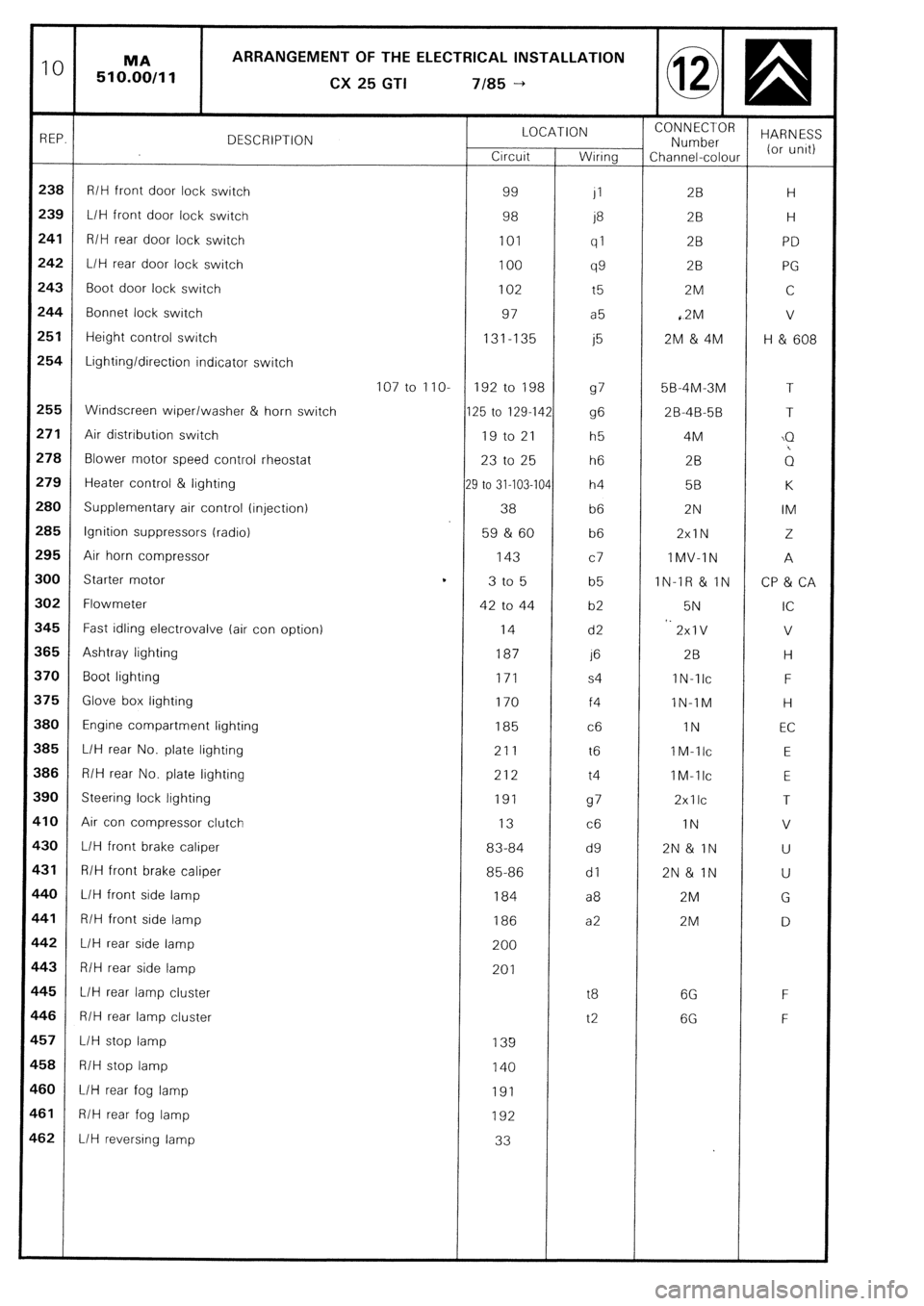
10 MA ARRANGEMENT OF THE ELECTRICAL INSTALLATION
510.00/11
CX
25 GTI 7185 -+
REP. DESCRIPTION LOCATION CONNECTOR
Number HARNESS
Crrcuit Wiring Channel-colour (or unrt)
238 R/H front door lock switch 99
JI 2B H
239
L/H front door lock switch 98
j8 2B H
241 R/H rear door lock switch 101
ql 28 PD
242 L/H rear door lock switch 100
99 28 PG
243 Boot door lock switch 102 t5 2M C
244 Bonnet lock switch 97 a5 ,2M v
251 Height control switch 131-135
j5 2M & 4M H & 608
254 Lighting/direction indicator switch
107 to IIO- 192 to 198
97 5B-4M-3M T
255 Windscreen wiper/washer & horn switch 125 to 129-142
96 2B-4B-5B T
271 Air distribution switch 19 to 21 h5 4M \Q
278 Blower motor speed control rheostat 23 to 25 h6 2B ;1
279 Heater control & lighting
29 to 31-103-104 h4 58 K
280 Supplementary air control (injection) 38 b6 2N IM
285 Ignition suppressors (radio) 59 & 60 b6 2xlN 2
295
Air horn compressor 143
c7 IMV-IN A
300
Starter motor t
3 to 5 b5 IN-IR & IN CP & CA
302 Flowmeter 42 to 44 b2 5N IC
545 Fast idling electrovalve (air con option) 14 d2 *. 2xlV V
$65 Ashtray lighting 187 1’3 2B H
$70 Boot lighting 171 s4 IN-TIC F
i75 Glove box lighting 170 f4 lN-IM H
I80 Engine compartment lighting 185 c6 IN EC
385 L/H rear No. plate lighting 211 t6 IM-llc E
386 R/H rear No. plate lighting 212 t4 IM-llc
E
390 Steering lock lighting 191
97 2xllc T
$10 Air con compressor clutch 13
c6 IN V
$30 L/H front brake caliper 83-84 d9 2N& IN U
$31 R/H front brake caliper 85-86 dl 2N& IN U
140 L/H front side lamp 184 a8 2M G
F41 R/H front side lamp 186 a2 2M D
L42 L/H rear side lamp 200
c43
R/H rear side lamp 201
145
L/H rear lamp cluster t8 6G F
C46 R/H rear lamp cluster t2 6G F
L57 L/H stop lamp 139
158 R/H stop lamp 140
160
L/H rear fog lamp 191
1-61 R/H rear fog lamp 192
.62 L/H reversing lamp 33