ECO DATSUN PICK-UP 1977 User Guide
[x] Cancel search | Manufacturer: DATSUN, Model Year: 1977, Model line: PICK-UP, Model: DATSUN PICK-UP 1977Pages: 537, PDF Size: 35.48 MB
Page 45 of 537

Condition
POOR
FUEL
ECONOMY
Se
the
xplanation
of
the
pow
r
dec
Oth
n
PROBLEM
IN
OTHER
FUNCTIONS
D
cr
d
oil
p
ssure
Excessive
wear
on
the
sliding
parts
Scuffing
of
sliding
parts
Floor
temperature
too
high
California
only
Engine
Tune
up
Probable
cause
Exceeding
idling
revolution
Inoperative
acceleration
recovery
Fuel
leakage
Malfunction
of
B
C
D
D
Malfunction
of
A
r
C
air
cleaner
Inadequate
oil
quality
Overheat
Worn
oil
pump
regulator
valve
Functional
deterioration
of
oil
pump
Blocked
oil
f1lter
Increased
clearance
in
various
sliding
parts
Blocked
oil
strainer
Inoperative
oil
gauge
pressure
switch
Oil
pressure
decreases
Improper
quality
or
contamination
of
oil
Damaged
air
cleaner
Overheat
or
overcoal
Improper
fuel
mixture
Decrease
of
oil
pressure
Insufficient
clearances
Overhea
t
Improper
fuel
mixture
Problem
in
fuel
system
Refer
to
Inspec
tion
of
Fuel
System
Problem
in
ignition
system
Refer
to
In
spection
of
Ignition
System
ET33
Corrective
action
Adjust
it
to
the
designated
rpm
Adjust
it
Repair
or
tighten
the
connection
of
fuel
pipes
Adjust
Check
and
replace
Use
the
designated
oil
Previously
mentioned
Disassemble
oil
pump
and
repair
or
renew
it
Repair
or
replace
it
with
a
new
one
Renew
it
Disassemble
and
replace
the
worn
parts
with
new
ones
Oeanit
Replace
it
with
a
new
one
Previousiy
mentioned
Exchange
the
oil
with
proper
one
and
change
element
Change
elemen
t
Previously
mentioned
Check
the
fuel
system
Previously
mentioned
Readjust
to
the
designated
clearances
Previously
mentioned
Check
the
fuel
system
Check
and
repair
Check
and
repair
Page 58 of 537
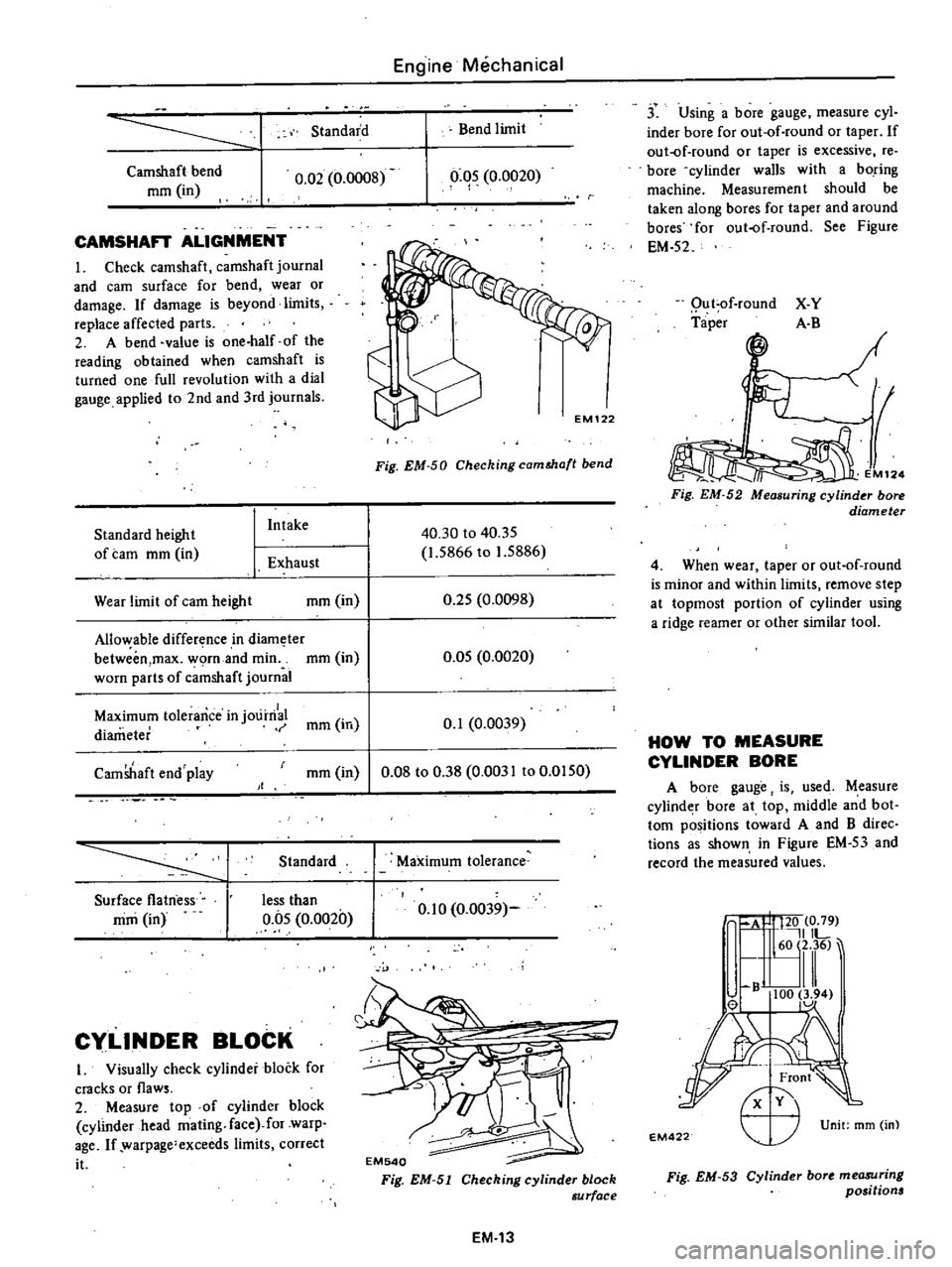
Standard
Camshaft
bend
mm
in
0
02
0
0008
CAMSHAFT
ALIGNMENT
I
Check
camshaft
camshaft
journal
and
earn
surface
for
bend
wear
or
damage
If
damage
is
beyond
limits
replace
affected
parts
2
A
bend
value
is
one
half
of
the
reading
obtained
when
camshaft
is
turned
one
full
revolution
with
a
dial
gauge
applied
to
2nd
and
3rd
journals
Standard
height
of
tam
mm
in
I
Intake
1
Exhaust
Wear
limit
of
earn
height
mm
in
Allo
able
difference
in
diam
ter
betweim
max
worn
and
min
mm
in
worn
parts
of
c
mshaft
journal
Engine
Mechanical
Bend
limit
0
05
0
0020
I
Fig
EM
50
Checking
camMa
t
bend
40
30
to
40
35
1
5866
to
1
5886
0
25
0
0098
0
05
0
0020
Maximum
tolerance
in
j01
irri
mm
in
0
1
0
0039
diameter
CamShaft
end
play
mm
in
0
08
to
0
38
0
0031
to
0
0150
Standard
Surface
flatness
mm
in
less
than
0
05
0
0020
Cy
LlNDER
BLOCK
I
Visually
check
cylinder
block
for
cracks
or
flaws
2
Measure
top
of
cylinder
block
cylinder
head
mating
face
for
warp
age
If
warpage
exceeds
limits
correct
it
Maximum
tolerance
0
10
0
0039
EM540
Fig
EM
51
Cheching
cylinder
block
au
rface
EM
13
j
Using
a
bore
gauge
measure
cyl
inder
bore
for
out
of
round
or
taper
If
out
of
round
or
taper
is
excessive
re
bore
cylinder
walls
with
a
boring
machine
Measuremen
t
should
be
taken
along
bores
for
taper
and
around
bores
for
out
of
round
See
Figure
EM
52
Qu
t
of
round
Taper
X
Y
A
B
M12
Fig
EM
52
Measuring
cylinder
bore
diameter
4
When
wear
taper
or
out
of
round
is
minor
and
within
limits
remove
step
at
topmost
portion
of
cylinder
using
a
ridge
reamer
or
other
similar
tool
HOW
TO
MEASURE
CYLINDER
BORE
A
bore
gauge
is
used
Measure
cylind
r
bore
at
top
middle
and
bot
tom
positions
toward
A
and
B
direc
tions
as
shown
in
Figure
EM
53
and
record
the
measured
values
A
I
120
0
79
IlL
60
2
36
lll
B
100
3
94
el
1
Unit
mm
m
EM
22
r
Fig
EM
53
Cylinder
bort
me08Uring
positions
Page 59 of 537
Engine
Mechanical
Standard
Wear
limit
Inner
diameter
85
000
to
85
050
0
2
0
0079
3
3465
to
3
3484
Cylinder
bore
mm
in
Out
of
round
O
ot5
0
0006
Taper
0
015
0
0006
Difference
in
cylinder
bore
0
05
0
0020
0
2
0
0079
mm
in
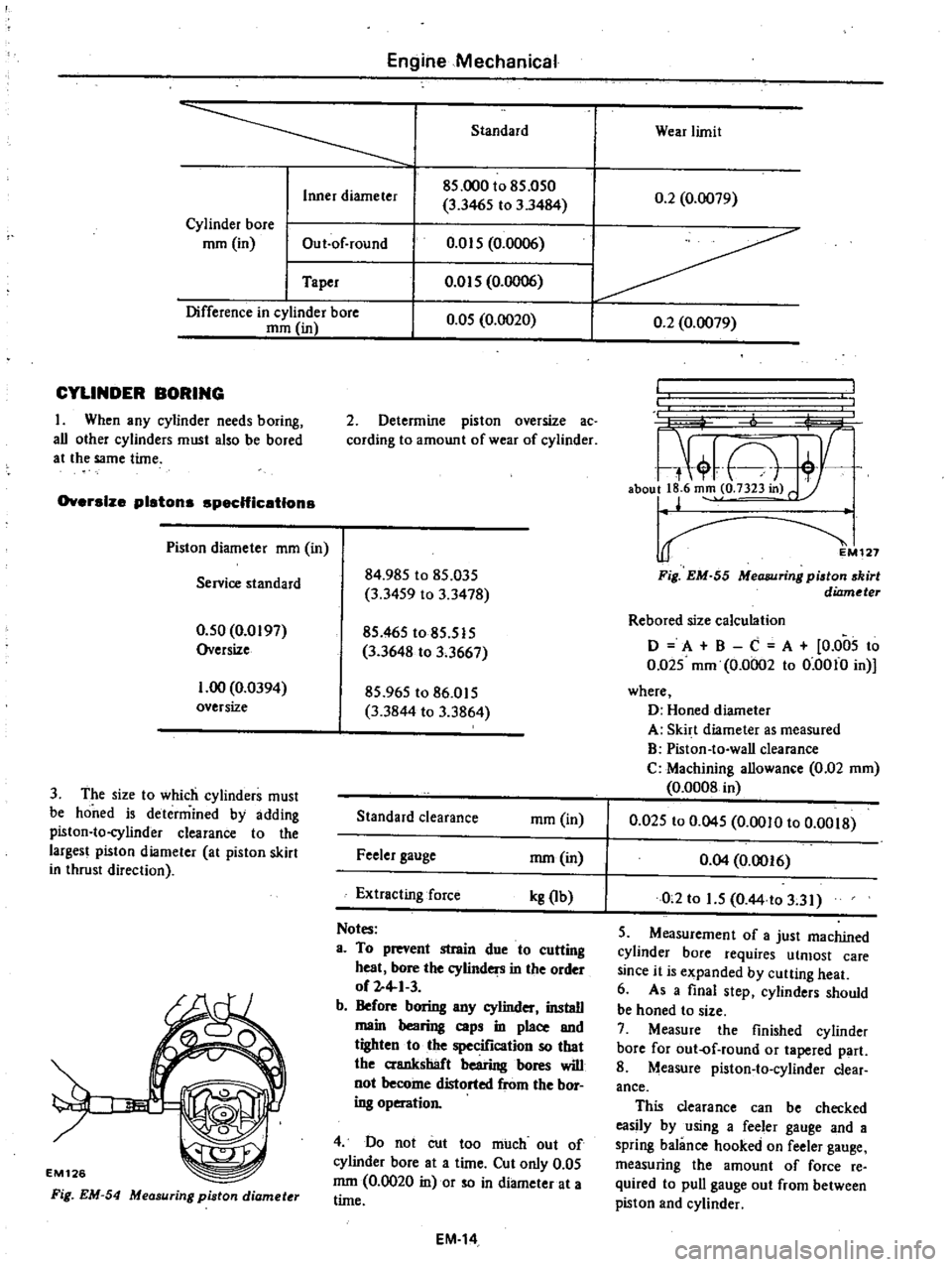
CYLINDER
BORING
I
When
any
cylinder
needs
boring
all
other
cylinders
must
also
be
bored
at
the
same
time
Oversize
pistons
spec
Hic
etlons
Piston
diameter
mm
in
Servioe
standard
0
50
0
0197
Oversize
1
00
0
0394
oversize
3
The
size
to
which
cylinders
must
be
honed
is
determined
by
adding
piston
to
cylinder
clearance
to
the
largest
piston
diameter
at
piston
skirt
in
thrust
direction
EM126
Fig
EM
54
Measuring
piston
diamet
r
2
Determine
piston
oversize
ac
cording
to
amount
of
wear
of
cylinder
84
985
to
85
035
3
3459
to
3
3478
85
465
to
85
515
3
3648
to
3
3667
85
965
to
86
015
3
3844
to
3
3864
Standard
clearance
ffim
in
Feeler
gauge
mm
in
Extracting
force
kg
Ib
Notes
a
To
prevent
strain
due
to
cutting
heat
bore
the
cylinders
in
the
order
of
2
4
1
3
b
Before
boring
any
cylinder
install
main
bearing
caps
in
place
and
tighten
to
the
specification
so
that
the
crankshaft
bearing
bores
will
not
become
distorted
from
the
bor
ing
operation
4
Do
not
cut
too
much
out
of
cylinder
bore
at
a
time
Cut
only
0
05
mm
0
0020
in
or
so
in
diameter
at
a
time
EM
14
L
7
A
aboull
6
m
o
7323in
r
127
Fig
EM
55
MeCUJlJring
piston
skirt
diameter
Rebored
size
calculation
o
A
B
C
A
0
005
to
0
Q25
mm
0
0002
to
0
0010
in
where
D
Honed
diameter
A
Skirt
diameter
as
measured
B
Piston
to
wall
clearance
C
Machining
allowance
0
02
mm
0
0008
in
0
025
to
0
045
0
0010
to
0
0018
0
04
0
0016
0
2
to
1
5
O
44
to
3
31
5
Measurement
of
a
just
machined
cylinder
bore
requires
utmost
care
since
it
is
expanded
by
cutting
heat
6
As
a
final
step
cylinders
should
be
honed
to
size
7
Measure
the
finished
cylinder
bore
for
out
of
round
or
tapered
part
8
Measure
piston
to
cylinder
clear
ance
This
clearance
can
be
checked
easily
by
using
a
feeler
gauge
and
a
spring
balance
hooked
on
feeler
gauge
measuring
the
amount
of
force
re
quired
to
pull
gauge
out
from
between
piston
and
cylinder
Page 60 of 537

Engine
Mechanical
Notes
a
When
measuring
clearance
slowly
pull
feeier
gaUge
siraight
upward
b
It
Is
reConUnended
that
piston
and
cylinder
be
hel
ted
to
200C
680F
PISTONS
PISTON
PINS
AND
PISTON
RINGS
I
Remove
carbon
from
piston
and
ring
grooves
with
a
ca
bon
scraper
and
a
curved
steel
wire
Clean
out
oil
slots
in
bottom
land
of
oil
ring
groove
2
Check
for
damage
scratches
and
wear
Replace
if
necessary
3
Meas1
1re
side
clearance
of
rings
in
ring
grooves
as
each
ring
is
installed
Side
clearance
should
be
as
follows
00
I
EM542
Fig
EM
58
Measuring
ring
gap
Notes
a
When
piston
ring
only
is
to
be
replaced
without
cylinder
bore
being
corrected
measure
gap
at
bottom
of
cylinder
where
wear
is
minor
b
Oversize
piston
rings
are
available
for
serv
ce
Oversize
0
5
mm
0
0197
in
and
1
0
mm
0
0394
in
5
Measure
piston
pin
hole
in
rela
tion
to
outer
diameter
of
pin
If
wear
exceeds
limit
replace
each
piston
pin
together
with
the
piston
on
which
it
is
installed
6
Determine
the
fitting
of
piston
pin
into
piston
pin
hole
to
such
an
extent
that
it
can
be
finger
pressed
at
room
temperature
This
piston
pin
must
be
a
tight
pre
s
fit
into
connect
ing
rod
t
J
f
rr
11
1
I
EM541
Fig
EM
56
Measuring
piaton
fit
in
cylinder
Fig
EM
57
Measuring
piston
ring
side
clearance
Side
clearance
Unit
mm
in
I
Second
ring
I
I
Wear
limit
Standard
0
040
to
0
073
0
0016
to
0
0029
0
030
to
0
070
I
0
0012
to
0
0028
I
Top
ring
0
1
0
0039
Oil
ring
f
feeler
gauge
Ring
should
be
placed
to
diameter
at
upper
or
lower
limit
of
ring
travel
4
Push
ring
into
cylinder
with
pis
ton
so
as
to
place
it
squarely
in
cylinder
measure
ring
gap
with
a
EM131
Ring
gap
Fig
EM
59
Piston
pin
fitting
Unit
rom
in
Standard
Wear
limit
0
25
to
0
40
0
0098
to
0
0157
0
30
to
0
50
0
0
II
8
to
0
0197
Top
ring
Second
ring
1
0
0
0394
EM132
0
30
to
0
90
0
0118
to
0
0354
Oil
ring
Fig
EM
60
Measuring
pi
ton
pin
diamet
EM
15
Page 64 of 537
Engine
Mechanical
Connectlns
rod
be
rlns
undersize
SID
0
25
0
0098
Undersize
0
50
0
0197
Undersize
0
75
0
0295
Undersize
MISCELLANEOUS
COMPONENTS
CRANKSHA
AND
CAMSHA
SPROCKETS
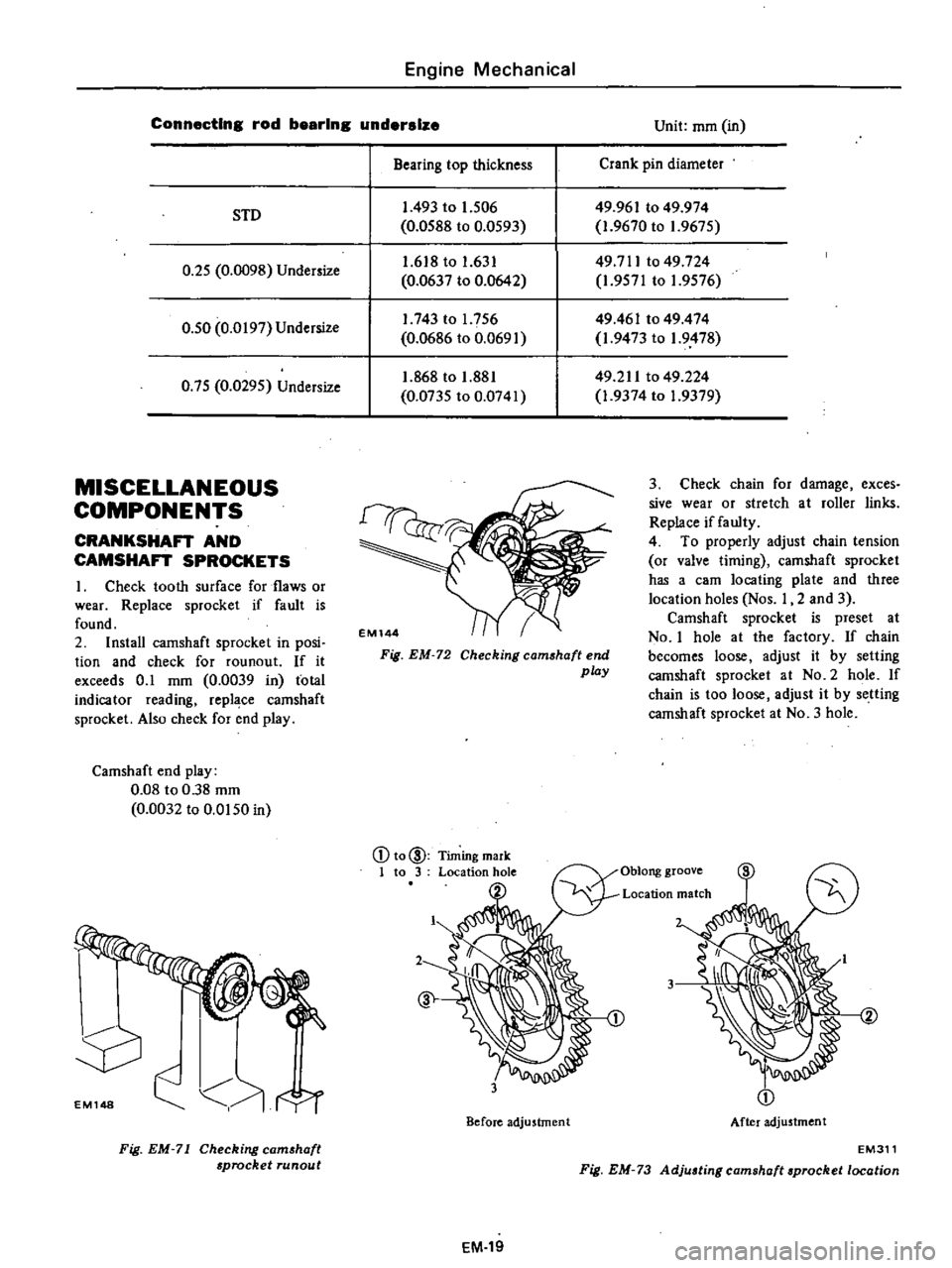
I
Check
tooth
surface
for
flaws
or
wear
Replace
sprocket
if
fault
is
found
2
Install
camshaft
sprocket
in
posi
tion
and
check
for
rounout
If
it
exceeds
0
1
mm
0
0039
in
total
indicator
reading
repl
ce
camshaft
sprocket
Also
check
for
end
play
Camshaft
end
play
0
08
to
0
38
mm
0
0032
to
0
0150
in
EMl48
Fig
EM
71
Checking
eam
haft
sprocket
Tunaut
Unit
mm
in
Bearing
top
thickness
Crank
pin
diameter
1
493
to
1
506
0
0588
to
0
0593
49
961
to
49
974
1
9670
to
1
9675
49711
to
49
724
1
9571
to
1
9576
1
618
to
1
631
0
0637
to
0
0642
1
743
to
1
756
0
0686
to
0
0691
49461
to
49
474
1
9473
to
1
9478
1
868
to
1
881
0
0735
to
0
0741
49
211
to
49
224
1
9374
to
1
9379
Fig
EM
72
Checking
camshaft
end
play
3
Check
chain
for
damage
exces
sive
wear
or
stretch
at
roller
links
Replace
if
faulty
4
To
properly
adjust
chain
tension
or
valve
timing
camshaft
sprocket
has
a
earn
locating
plate
and
three
location
holes
Nos
I
2
and
3
Camshaft
sprocket
is
preset
at
No
I
hole
at
the
factory
If
chain
becomes
loose
adjust
it
by
setting
camshaft
sprocket
at
NO
2
hole
If
chain
is
too
loose
adjust
it
by
setting
camshaft
sprocket
at
No
3
hole
2
3
Before
adjustment
Location
match
3
After
adju5tmen
t
EM311
Fig
EM
73
Adjuating
camshaft
aprocket
location
EM
19
Page 65 of 537
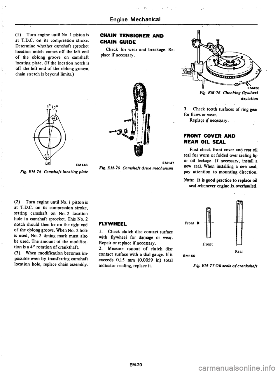
I
Turn
engine
until
No
I
piston
is
at
T
D
C
on
its
compression
stroke
Determine
whether
camshaft
sprocket
location
notch
comes
off
the
left
end
of
the
oblong
groove
on
camshaft
locating
plate
If
the
location
notch
is
off
the
left
end
of
the
oblong
groove
chain
stretch
is
beyond
limits
40150
EMl46
Fig
EM
74
Camshafllocating
plate
2
Turn
engine
until
No
I
piston
is
at
T
D
C
on
its
compression
stroke
setting
camshaft
on
No
2
location
hole
in
camshaft
sprocket
This
No
2
notch
should
then
be
on
the
right
end
of
the
oblong
groove
When
No
2
hole
is
used
NO
2
timing
mark
must
also
be
used
The
amount
of
the
modifica
tion
is
a
40
rotation
of
crankshaft
3
When
modification
becomes
im
possible
even
by
transferring
camshaft
location
hole
replace
chain
assembly
Engine
Mechanical
CHAIN
TENSIONER
AND
CHAIN
GUIDE
Check
for
wear
and
breakage
Re
place
if
necessary
r
I
L
EM147
Fig
EM
75
Cam
haft
dri
mechanilm
FLYWHEEL
I
Check
clutch
disc
contact
surface
with
flywheel
for
damage
or
wear
Repair
or
replace
if
necessary
2
Measure
runout
of
clutch
disc
contact
surface
with
a
dial
gauge
fit
exceeds
0
15
mm
0
0059
in
total
indicator
reading
replace
it
EM
20
EM426
Fig
EM
76
Checking
flywheel
deviation
3
Check
tooth
surfaces
of
ring
gear
for
flaws
or
wear
Replace
if
necessary
FRONT
COVER
AND
REAR
OIL
SEAL
First
check
front
cover
an
rear
oil
seal
for
worn
or
folded
over
sealing
lip
or
oil
leakage
If
necessary
install
a
new
seal
When
installing
a
new
seal
pay
attenti
on
to
mounting
direction
Note
It
is
good
practice
to
replace
oil
seal
whenever
engine
is
overhauled
Frant
t
r
r
J
I
Front
Real
EM150
Fig
EM
77
Oil
eals
of
crank
haft
Page 67 of 537
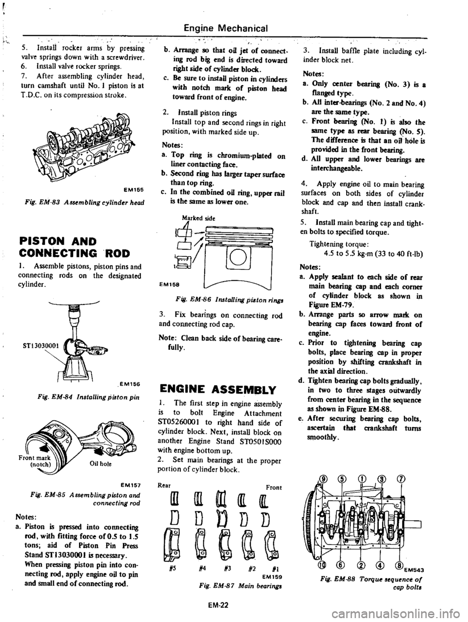
5
Install
rocker
arms
by
pressing
valve
springs
down
with
a
screwdriver
6
Install
valve
rocker
springs
7
After
assembling
cylinder
head
turn
camshaft
until
No
I
piston
is
at
T
D
C
on
its
compression
stroke
EM1S5
Fig
EM
83
A
embling
cylinder
head
PISTON
AND
CONNECTINGROD
1
Assemble
pistons
piston
pins
and
connecting
rods
on
the
de
ignated
cylinder
STl3030001
EM156
Fig
EM
84
Installing
piston
pin
EM157
Fig
EM
85
Assembling
piston
and
connecting
rod
Notes
a
Piston
is
pressed
into
connecting
rod
with
fitting
force
of
0
5
to
5
tons
aid
of
Piston
Pin
Press
Stand
STl303000
I
is
necessary
When
pressing
piston
pin
into
con
necting
rod
apply
engine
oil
to
pin
and
small
end
of
connecting
rod
Engine
Mechanical
b
Arrange
so
that
oil
jet
of
connect
ing
rod
big
end
is
directed
toward
right
side
of
eylinder
block
c
Be
sure
to
install
piston
in
cylinders
with
notch
mark
of
piston
head
toward
front
of
engine
2
Install
piston
rings
InstalI
top
and
second
rings
in
right
position
with
marked
side
up
Notes
a
Top
ring
is
chromium
plated
on
liner
contacting
face
b
Second
ring
has
larger
taper
surface
than
top
ring
c
In
the
combined
oil
ring
upper
rail
is
the
same
as
lower
one
j
c6J
EM158
Fig
EM
86
lalling
pidon
rings
3
Fix
bearings
on
connecting
rod
and
connecting
rod
cap
Note
Clean
back
side
of
bearing
care
fully
ENGINE
ASSEMBLY
The
first
step
in
engine
assembly
is
to
bolt
Engine
Attachment
ST0526000
I
to
right
hand
ide
of
cylinder
block
Next
install
block
on
another
Engine
Stand
ST0501S000
with
engine
bottom
up
2
Set
main
bearings
at
the
proper
portion
of
cylinder
block
Rear
Front
III
III
m
It
IlL
D
D
D
D
D
1
5
1
4
1
3
1
2
1
1
EM159
Fig
EM
87
Main
bearings
EM
22
3
Install
baffle
plate
including
cyl
inder
block
net
Notes
a
Only
center
bearing
No
3
is
a
flanged
type
b
All
inter
bearings
No
2
and
No
4
are
the
same
type
c
Front
bearing
No
I
is
also
the
same
type
as
rear
bearing
No
5
The
difference
is
that
an
oil
hole
is
provided
in
the
front
bearing
d
All
upper
and
lower
bearings
are
interchangeable
4
Apply
engine
oil
to
main
bearing
surfaces
on
both
sides
of
cylinder
block
and
cap
and
then
install
crank
shaft
5
Install
main
bearing
cap
and
tight
en
bolts
to
specified
torque
Tightening
torque
4
5
to
5
5
kg
m
33
to
40
ft
lb
Notes
a
Apply
sealant
to
each
side
of
rear
main
bearing
cap
and
each
comer
of
eylinder
block
as
shown
in
Figure
EM
79
b
Arrange
parts
so
arrow
mark
on
bearing
cap
faces
toward
front
of
engine
c
Prior
to
tightening
bearing
cap
bolts
place
bearing
cap
in
proper
position
by
shifting
crankshaft
in
the
axial
direction
d
Tighten
bearing
cap
bolts
gradually
in
two
to
three
stages
outwardly
from
center
bearing
in
the
sequence
as
shown
in
Figure
EM
88
e
After
securing
bearing
cap
bolts
ascertain
that
aankshaft
turns
smoothly
@
i
d
l
j
1
@EM543
Fig
EM
8S
Torque
sequence
0
cap
bolt
Page 69 of 537
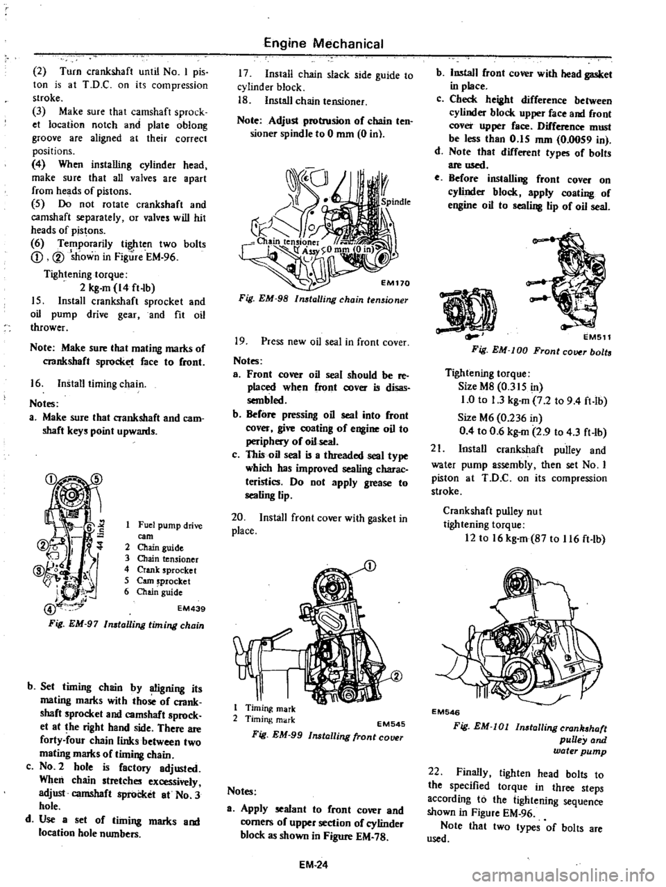
2
Turn
crankshaft
until
No
I
pis
ton
is
at
T
D
C
on
its
compression
stroke
3
Make
sure
thai
camshaft
sprock
et
location
notch
and
plate
oblong
groove
are
aligned
at
their
correct
positions
4
When
installing
cylinder
head
make
sure
that
all
valves
are
apart
from
heads
of
pistons
5
Do
not
rotate
crankshaft
and
camshaft
separately
or
valves
will
hit
heads
of
pistons
6
Temporarily
tighten
two
bolts
CD
V
sJiown
in
Fig
re
EM
96
Tightening
torque
2
kg
m
14
ft
b
15
Install
crankshaft
sprocket
and
oil
pump
drive
gear
and
fit
oil
thrower
Note
Make
sure
lhat
maling
marks
of
crankshaft
sprocket
face
10
Cront
16
Install
timing
chain
Noles
a
Make
sure
that
crankshaft
and
cam
shaft
keys
point
upwards
Fuel
pump
drive
earn
2
Chain
guide
3
Chain
tensioner
4
Crank
sprocket
5
earn
sprocket
6
Chai
guide
EM439
b
Set
timing
chain
by
OOgning
its
mating
marks
with
those
oC
crank
shaft
sprocket
and
camshaft
sprock
et
at
the
right
hand
side
There
are
forty
four
chain
links
between
two
mating
marks
of
timing
chain
c
NO
2
hole
is
Cactory
adjusted
When
chain
stretches
excessively
adjust
camshaft
sprocket
at
No
3
hole
d
Use
a
set
of
timing
marks
and
location
hole
numbers
Engine
Mechanical
17
Install
chain
slack
side
guide
to
cylinder
block
18
Install
chain
tensioner
Note
Adjust
protrusion
oC
chain
ten
sioner
spindle
to
0
mm
0
in
Fig
EM
98
lmtalling
chain
tensioner
19
Press
new
oil
seal
in
front
cover
Notes
a
Front
cover
oil
seal
should
be
reo
placed
when
Cront
cover
is
disas
sembled
b
BeCore
pressing
oil
seal
into
Cront
cover
give
coating
of
engine
oil
to
periphery
of
oil
seal
c
This
oil
seal
is
a
threaded
seal
type
which
has
improved
sealing
charac
teristics
Do
not
apply
grease
to
sealing
lip
20
Install
front
cover
with
gasket
in
place
1
Timing
mark
2
Timing
mark
EM545
Fig
EM
99
Installing
fronl
COlHlr
Notes
a
Apply
sealant
to
Cront
cover
and
corners
oC
upper
section
of
cylinder
block
as
shown
in
Figure
EM
78
EM
24
b
Install
Cront
cover
with
head
gasket
in
place
c
Check
height
diCCerence
between
cylinder
block
upper
Cace
and
Cront
cover
upper
Cace
DifCerence
must
be
less
than
0
15
mm
0
0059
in
d
Note
that
difCerent
types
oC
bolts
are
used
e
Before
installing
front
cover
on
cylinder
block
apply
coating
oC
engine
oil
10
sealing
lip
of
oil
seal
EMS11
Fig
EM
lOD
Front
cover
bolts
Tightening
torque
Size
M8
0
315
in
1
0
to
1
3
kg
m
7
2
to
9
4
ft
lb
Size
M6
0
236
in
0
4
to
0
6
kg
m
2
9
to
4
3
ft
lb
21
Install
crankshaft
pulley
and
water
pump
assembly
then
set
No
I
piston
at
ToO
C
on
its
compression
stloke
Crankshaft
pulley
nu
I
tightening
torque
12
to
16
kg
m
B7
to
116
ft
lb
EM546
Fig
EM
Ol
lnstallingcran
haft
pulley
and
water
pump
22
Finally
tighten
head
bolts
to
the
specified
torque
in
three
steps
according
to
the
lightening
sequence
shown
in
Figure
EM
96
Note
thai
Iwo
types
of
bolts
are
used
Page 71 of 537
30
Install
heatshieid
plate
on
mani
fold
assembly
31
Install
air
gallery
pipe
on
ex
haust
manifold
32
Install
manifold
gasket
and
manifold
assembly
on
cylinder
head
Tightening
torque
1
2to
1
6kg
m
8
7
to
11
6
ft
lb
33
Install
blow
by
gas
pipe
on
cyl
inder
block
and
tighten
with
rear
engine
slinger
34
Install
thermostat
housing
gas
ket
thermostat
housing
and
thermo
stat
35
Install
thermal
vacuum
valve
on
thermostat
housing
Before
installing
apply
a
liquid
packing
slightly
to
the
threads
36
Install
FJ
C
D
bracket
on
cylin
der
head
37
Install
E
G
R
passage
and
E
G
R
valve
on
intake
manifold
38
Connect
E
G
R
tube
to
E
G
R
tube
and
exhaust
manifold
39
Install
check
valve
on
air
gallery
pipe
40
Install
air
cleaner
bracket
on
intake
manifold
41
Install
air
control
valve
on
air
cleaner
bracket
California
models
42
Install
vacuum
and
fuel
tubes
combined
on
cylinder
head
43
Install
distributor
assembly
44
Install
heatshield
plate
joint
seat
and
carburetor
Carbure10r
tightening
torque
0
5
to
1
0
kg
m
3
6
to
7
2
ft
lb
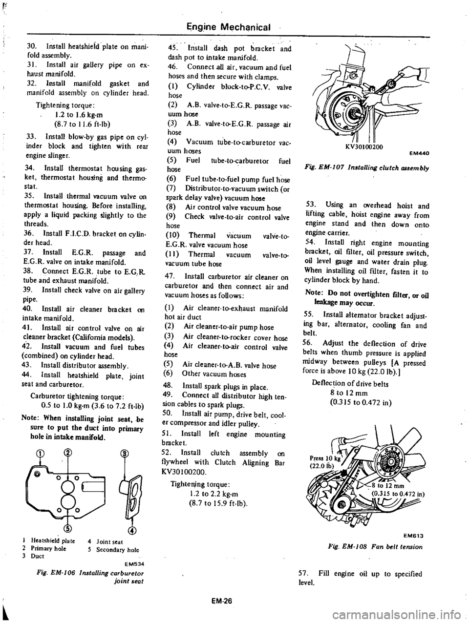
Note
When
instalUng
joint
seat
be
sure
to
put
the
duct
into
primary
hole
in
intake
manifold
S
J
Heatshield
plate
4
Joint
seat
2
Primary
hole
5
Secondary
hole
3
Duct
EM534
Fig
EM
I06
Installing
carburetor
joint
seat
Engine
Mechanical
45
Install
dash
pot
bracket
and
dash
pot
to
intake
manifold
46
Connect
all
air
vacuum
and
fuel
hoses
and
then
secure
with
clamps
I
Cylinder
block
to
P
C
V
valve
hose
2
A
B
valve
to
E
G
R
passage
vac
uum
hose
3
A
B
valve
to
E
G
R
passage
air
hose
4
Vacuum
tube
to
carburetor
vac
uum
hoses
5
Fuel
ube
to
carburetor
fuel
hose
6
Fuel
tube
to
fuel
pump
fuelhose
7
Distributor
to
vacuum
switch
or
spark
delay
valve
vacuum
hose
8
Air
control
valve
vacuum
hose
9
Check
valve
to
air
control
valve
hose
10
Thermal
vacuum
valve
to
E
G
R
valve
vacuum
hose
I
I
Thermal
vacuum
valve
to
vacuum
tube
hose
47
Install
carburetor
air
cleaner
on
carburetor
and
then
connect
air
and
vacuum
hoses
as
follows
I
Air
cleaner
to
exhaust
manifold
hot
air
duct
2
Air
c1eaner
to
air
pump
hose
3
Air
cleaner
to
rocker
cover
hose
4
Air
cleaner
to
air
control
valve
hose
5
6
48
Install
spark
plugs
in
place
49
Connect
all
distributor
high
ten
sion
cables
to
spark
plugs
50
Install
air
pump
drive
belt
cool
er
compressor
and
idler
pulley
51
Install
left
engine
mounting
bracket
52
Install
clutch
assembly
on
flywheel
with
Clutch
Aligning
Bar
KV30100200
Air
cleaner
to
A
B
valve
hose
Other
vacuum
hoses
Tightening
torque
1
2
to
2
2
kg
m
8
7
to
15
9
ft
lb
EM
26
I
I
KV30100200
EM440
Fig
EM
I07
In
talling
clutch
embly
53
Using
an
overhead
hoist
and
lifting
cable
hoist
engine
away
from
engine
stand
and
then
down
onto
engine
carrier
54
Install
right
engine
mounting
bracket
oil
filter
oil
pressure
switch
oil
level
gauge
and
water
drain
plug
When
installing
oil
filter
fasten
it
to
cylinder
block
by
hand
Note
Do
not
overtighten
flit
or
oil
leakage
may
occur
55
Install
alternator
bracket
adjust
ing
bar
alternator
cooling
fan
and
belt
56
Adjust
the
deflection
of
drive
belts
when
thumb
pressure
is
applied
midway
between
pulleys
A
pressed
force
is
above
10
kg
22
0
lb
Deflection
of
drive
belts
8
to
12
mm
0
315
to
0
472
in
EM613
Fig
EM
lOB
Fan
belt
tension
57
Fill
engine
oil
up
to
specified
level
Page 74 of 537
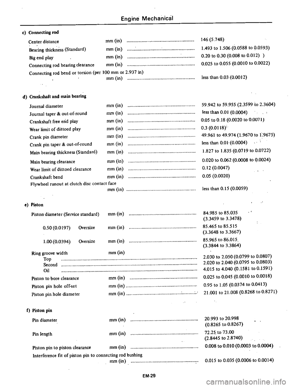
Engine
Mechanical
c
Connecting
rod
Center
distance
mm
in
Bearing
thickness
Standard
mm
in
Big
end
play
mm
in
Connecting
rod
bearing
clearance
mm
in
Connecting
rod
bend
or
torsion
per
100
mm
or
2
937
in
mm
in
d
Crankshaft
and
main
bearing
Journal
diameter
Journal
taper
out
of
round
Crankshaft
free
end
play
Wear
limit
of
dittoed
play
Crank
pin
diameter
Crank
pin
taper
out
of
round
Main
bearing
thickness
StJlndard
146
5
748
1
493
to
1
506
0
0588
to
0
0593
0
20
to
0
30
0
008
to
0
012
0
D25
to
0
055
0
0010
to
0
0022
less
than
0
03
0
0012
mm
in
mm
in
mm
in
mm
in
mm
in
mm
in
mm
in
59
942
to
59
955
2
3599
io
2
3604
less
than
0
0
I
0
0004
0
05
to
0
18
0
0020
to
0
0071
0
3
0
0118
49
961
to
49
974
1
9670
to
1
9675
less
than
0
01
0
0004
1
827
to
1
835
0
0719
to
0
0722
0
020
to
0
062
0
0008
to
0
0024
0
12
0
0047
0
05
0
0020
Main
bearing
clearance
mm
in
Wear
limit
of
dittoed
clearance
mm
in
Crankshaft
bend
mm
in
Flywheel
runout
at
clutch
disc
contact
face
mm
in
e
Piston
Pistondiarneter
Service
standard
0
50
0
0197
Oversize
1
00
0
0394
Oversize
Ring
groove
width
Top
Second
Oil
Piston
to
bore
clearance
Piston
pin
hole
off
set
Piston
pin
hole
diameter
f
Piston
pin
Pin
diameter
Pin
length
less
than
0
15
0
0059
mm
in
84
985
to
85
035
3
3459
to
3
3478
85
465
to
85
515
3
3648
to
3
3667
85
965
to
86
015
3
3844
to
3
3864
2
030
to
2
050
0
0799
to
0
0807
2
020
to
2
040
0
0795
to
0
0803
4
015
to
4
040
0
1581
to
0
1591
0
Q25
to
0
045
0
0010
to
0
0018
0
95
to
1
05
0
0374
to
0
0413
21
001
to
21
008
0
8268
to
0
8271
mm
in
mm
in
mm
in
mm
in
mm
in
mm
in
mm
in
20
993
to
20
998
0
8265
to
0
8267
72
25
to
73
00
2
8445
to
2
8740
0
008
to
om
0
0
0003
to
0
0004
mm
in
Piston
pin
to
piston
clearance
mm
in
Interference
fit
of
piston
pin
to
connecting
rod
bushing
mm
in
om
5
to
0
035
0
0006
to
0
00
I
4
EM
29