air condition DODGE CHARGER 2017 7.G Owners Manual
[x] Cancel search | Manufacturer: DODGE, Model Year: 2017, Model line: CHARGER, Model: DODGE CHARGER 2017 7.GPages: 530, PDF Size: 4.72 MB
Page 42 of 530
The seat belt webbing retractor will lock only during very
sudden stops or collisions. This feature allows the shoulder
part of the seat belt to move freely with you under normal
conditions. However, in a collision the seat belt will lock
and reduce your risk of striking the inside of the vehicle or
being thrown out of the vehicle.
WARNING!
•Relying on the air bags alone could lead to more
severe injuries in a collision. The air bags work with
your seat belt to restrain you properly. In some
collisions, the air bags won’t deploy at all. Always
wear your seat belt even though you have air bags.
• In a collision, you and your passengers can suffer
much greater injuries if you are not properly buckled
up. You can strike the interior of your vehicle or
other passengers, or you can be thrown out of the
vehicle. Always be sure you and others in your
vehicle are buckled up properly.
• It is dangerous to ride in a cargo area, inside or
outside of a vehicle. In a collision, people riding in
these areas are more likely to be seriously injured or
killed.
(Continued)
WARNING! (Continued)
•Do not allow people to ride in any area of your
vehicle that is not equipped with seats and seat belts.
• Be sure everyone in your vehicle is in a seat and
using a seat belt properly. Occupants, including the
driver, should always wear their seat belts whether
or not an air bag is also provided at their seating
position to minimize the risk of severe injury or
death in the event of a crash.
• Wearing your seat belt incorrectly could make your
injuries in a collision much worse. You might suffer
internal injuries, or you could even slide out of the
seat belt. Follow these instructions to wear your seat
belt safely and to keep your passengers safe, too.
• Two people should never be belted into a single seat
belt. People belted together can crash into one an-
other in a collision, hurting one another badly. Never
use a lap/shoulder belt or a lap belt for more than one
person, no matter what their size.
40 THINGS TO KNOW BEFORE STARTING YOUR VEHICLE
Page 51 of 530
Air Bag Warning Light
The ORC monitors the readiness of the electronic
parts of the air bag system whenever the ignition
switch is in the START or ON/RUN position. If
the ignition switch is in the OFF position or in the
ACC position, the air bag system is not on and the air bags
will not inflate.
The ORC contains a backup power supply system that may
deploy the air bag system even if the battery loses power or
it becomes disconnected prior to deployment.
The ORC turns on the Air Bag Warning Light in the
instrument panel for approximately four to eight seconds
for a self-check when the ignition switch is first in the
ON/RUN position. After the self-check, the Air Bag Warn-
ing Light will turn off. If the ORC detects a malfunction in
any part of the system, it turns on the Air Bag Warning
Light, either momentarily or continuously. A single chime
will sound to alert you if the light comes on again after
initial startup.
The ORC also includes diagnostics that will illuminate the
instrument panel Air Bag Warning Light if a malfunction is
detected that could affect the air bag system. The diagnos-
tics also record the nature of the malfunction. While the air bag system is designed to be maintenance free, if any of the
following occurs, have an authorized dealer service the air
bag system immediately.
•
The Air Bag Warning Light does not come on during the
four to eight seconds when the ignition switch is first in
the ON/RUN position.
• The Air Bag Warning Light remains on after the four to
eight-second interval.
• The Air Bag Warning Light comes on intermittently or
remains on while driving.
NOTE: If the speedometer, tachometer, or any engine
related gauges are not working, the Occupant Restraint
Controller (ORC) may also be disabled. In this condition
the air bags may not be ready to inflate for your protection.
Have an authorized dealer service the air bag system
immediately.
WARNING!
Ignoring the Air Bag Warning Light in your instrument
panel could mean you won’t have the air bag system to
protect you in a collision. If the light does not come on
as a bulb check when the ignition is first turned on,
(Continued)
2
THINGS TO KNOW BEFORE STARTING YOUR VEHICLE 49
Page 80 of 530
Exhaust Gas
WARNING!
Exhaust gases can injure or kill. They contain carbon
monoxide (CO), which is colorless and odorless.
Breathing it can make you unconscious and can even-
tually poison you. To avoid breathing (CO), follow
these safety tips:
•Do not run the engine in a closed garage or in
confined areas any longer than needed to move your
vehicle in or out of the area.
• If you are required to drive with the trunk/liftgate/
rear doors open, make sure that all windows are
closed and the climate control BLOWER switch is set
at high speed. DO NOT use the recirculation mode.
• If it is necessary to sit in a parked vehicle with the
engine running, adjust your heating or cooling con-
trols to force outside air into the vehicle. Set the
blower at high speed. The best protection against carbon monoxide entry into the
vehicle body is a properly maintained engine exhaust
system.
Whenever a change is noticed in the sound of the exhaust
system, when exhaust fumes can be detected inside the
vehicle, or when the underside or rear of the vehicle is
damaged, have a competent mechanic inspect the complete
exhaust system and adjacent body areas for broken, dam-
aged, deteriorated, or mispositioned parts. Open seams or
loose connections could permit exhaust fumes to seep into
the passenger compartment. In addition, inspect the ex-
haust system each time the vehicle is raised for lubrication
or oil change. Replace as required.
Safety Checks You Should Make Inside The Vehicle
Seat Belts
Inspect the seat belt system periodically, checking for cuts,
frays, and loose parts. Damaged parts must be replaced
immediately. Do not disassemble or modify the system.
Front seat belt assemblies must be replaced after a collision.
Rear seat belt assemblies must be replaced after a collision
if they have been damaged (i.e., bent retractor, torn web-
bing, etc.). If there is any question regarding seat belt or
retractor condition, replace the seat belt.
78 THINGS TO KNOW BEFORE STARTING YOUR VEHICLE
Page 202 of 530
•The pointer shows the level of fuel in the fuel tank
when the Keyless Push Button Ignition is in the
ON/RUN position.
•
The fuel pump symbol points to the side of the
vehicle where the fuel door is located.
5. Temperature Gauge
•
The temperature gauge shows engine coolant tempera-
ture. Any reading within the normal range indicates that
the engine cooling system is operating satisfactorily.
• The gauge pointer will likely indicate a higher tem-
perature when driving in hot weather, up mountain
grades, or when towing a trailer. It should not be
allowed to exceed the upper limits of the normal
operating range.
WARNING!
A hot engine cooling system is dangerous. You or
others could be badly burned by steam or boiling
coolant. You may want to call an authorized dealer for
service if your vehicle overheats. If you decide to look
under the hood yourself, see “Maintaining Your Ve-
hicle”. Follow the warnings under the Cooling System
Pressure Cap paragraph.
CAUTION!
Driving with a hot engine cooling system could dam-
age your vehicle. If the temperature gauge reads “H”
pull over and stop the vehicle. Idle the vehicle with the
air conditioner turned off until the pointer drops back
into the normal range. If the pointer remains on the
“H”, turn the engine off immediately and call an
authorized dealer for service.
WARNING AND INDICATOR LIGHTS
The warning/indicator lights switch on in the instrument
panel together with a dedicated message and/or acoustic
signal when applicable. These indications are indicative
and precautionary and as such must not be considered as
exhaustive and/or alternative to the information contained
in the Owner ’s Manual, which you are advised to read
carefully in all cases. Always refer to the information in this
chapter in the event of a failure indication.
All active telltales will display first if applicable. The
system check menu may appear different based upon
equipment options and current vehicle status. Some tell-
tales are optional and may not appear.
200 UNDERSTANDING YOUR INSTRUMENT PANEL
Page 204 of 530
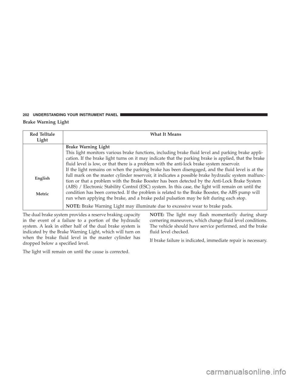
Brake Warning Light
Red TelltaleLight What It Means
English
Metric
Brake Warning Light
This light monitors various brake functions, including brake fluid level and parking brake appli-
cation. If the brake light turns on it may indicate that the parking brake is applied, that the brake
fluid level is low, or that there is a problem with the anti-lock brake system reservoir.
If the light remains on when the parking brake has been disengaged, and the fluid level is at the
full mark on the master cylinder reservoir, it indicates a possible brake hydraulic system malfunc-
tion or that a problem with the Brake Booster has been detected by the Anti-Lock Brake System
(ABS) / Electronic Stability Control (ESC) system. In this case, the light will remain on until the
condition has been corrected. If the problem is related to the Brake Booster, the ABS pump will
run when applying the brake, and a brake pedal pulsation may be felt during each stop.
NOTE:
Brake Warning Light may illuminate due to excessive wear to brake pads.
The dual brake system provides a reserve braking capacity
in the event of a failure to a portion of the hydraulic
system. A leak in either half of the dual brake system is
indicated by the Brake Warning Light, which will turn on
when the brake fluid level in the master cylinder has
dropped below a specified level.
The light will remain on until the cause is corrected. NOTE:
The light may flash momentarily during sharp
cornering maneuvers, which change fluid level conditions.
The vehicle should have service performed, and the brake
fluid level checked.
If brake failure is indicated, immediate repair is necessary.
202 UNDERSTANDING YOUR INSTRUMENT PANEL
Page 213 of 530
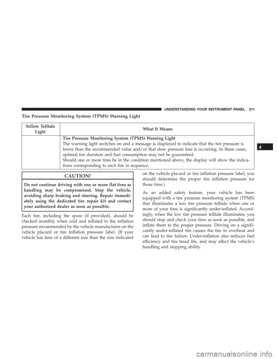
Tire Pressure Monitoring System (TPMS) Warning Light
Yellow TelltaleLight What It Means
Tire Pressure Monitoring System (TPMS) Warning Light
The warning light switches on and a message is displayed to indicate that the tire pressure is
lower than the recommended value and/or that slow pressure loss is occurring. In these cases,
optimal tire duration and fuel consumption may not be guaranteed.
Should one or more tires be in the condition mentioned above, the display will show the indica-
tions corresponding to each tire in sequence.
CAUTION!
Do not continue driving with one or more flat tires as
handling may be compromised. Stop the vehicle,
avoiding sharp braking and steering. Repair immedi-
ately using the dedicated tire repair kit and contact
your authorized dealer as soon as possible.
Each tire, including the spare (if provided), should be
checked monthly when cold and inflated to the inflation
pressure recommended by the vehicle manufacturer on the
vehicle placard or tire inflation pressure label. (If your
vehicle has tires of a different size than the size indicated on the vehicle placard or tire inflation pressure label, you
should determine the proper tire inflation pressure for
those tires.)
As an added safety feature, your vehicle has been
equipped with a tire pressure monitoring system (TPMS)
that illuminates a low tire pressure telltale when one or
more of your tires is significantly under-inflated. Accord-
ingly, when the low tire pressure telltale illuminates, you
should stop and check your tires as soon as possible, and
inflate them to the proper pressure. Driving on a signifi-
cantly under-inflated tire causes the tire to overheat and
can lead to tire failure. Under-inflation also reduces fuel
efficiency and tire tread life, and may affect the vehicle’s
handling and stopping ability.
4
UNDERSTANDING YOUR INSTRUMENT PANEL 211
Page 295 of 530
The following describes the left-hand control operation in
each mode.
Radio Operation
Pushing the top of the switch will “Seek” up for the next
listenable station and pushing the bottom of the switch will
“Seek” down for the next listenable station.
The button located in the center of the left-hand control
will tune to the next preset station that you have pro-
grammed in the radio preset button.
RADIO OPERATION AND MOBILE DEVICES
Under certain conditions, an “on” mobile device in your
vehicle can cause erratic or noisy performance from your
radio. This condition may be lessened or eliminated by
relocating the mobile device antenna. This condition is not
harmful to the radio. If your radio performance does not
satisfactorily “clear” by the repositioning of the antenna, it
is recommended that the radio volume be turned down or
off during mobile device operation when not using
Uconnect (if equipped).
Regulatory And Safety Information
USA/CANADA
Exposure to Radio Frequency Radiation
The radiated output power of the internal wireless radio is
far below the FCC radio frequency exposure limits. Nev-
ertheless, the wireless radio will be used in such a manner
that the radio is 8 inches (20 centimeters) or further from
the human body.
The internal wireless radio operates within guidelines
found in radio frequency safety standards and recommen-
dations, which reflect the consensus of the scientific com-
munity.
The radio manufacturer believes the internal wireless radio
is safe for use by consumers. The level of energy emitted is
far less than the electromagnetic energy emitted by wire-
less devices such as mobile phones. However, the use of
wireless radios may be restricted in some situations or
environments, such as aboard airplanes. If you are unsure
of restrictions, you are encouraged to ask for authorization
before turning on the wireless radio.
4
UNDERSTANDING YOUR INSTRUMENT PANEL 293
Page 296 of 530
This device complies with Part 15 of the FCC Rules and
with Industry Canada license-exempt RSS standard(s).
Operation is subject to the following two conditions:
1. This device may not cause harmful interference.
2. This device must accept any interference received, in-cluding interference that may cause undesired opera-
tion.
NOTE:
• This equipment has been tested and found to comply
with the limits for a Class B digital device, pursuant to
Part 15 of the FCC Rules. These limits are designed to
provide reasonable protection against harmful interfer-
ence in a residential installation. This equipment gener-
ates, uses and can radiate radio frequency energy and, if
not installed and used in accordance with the instruc-
tions, may cause harmful interference to radio commu-
nications. However, there is no guarantee that interfer-
ence will not occur in a particular installation. •
If this equipment does cause harmful interference to
radio or television reception, which can be determined
by turning the equipment off and on, the user is encour-
aged to try to correct the interference by one or more of
the following measures:
• Increase the separation between the equipment and
receiver.
• Consult the dealer or an experienced radio technician for
help.
CLIMATE CONTROLS
The Climate Control System allows you to regulate the
temperature, airflow, and direction of air circulating
throughout the vehicle. The controls are located on the
instrument panel below the radio.
294 UNDERSTANDING YOUR INSTRUMENT PANEL
Page 299 of 530
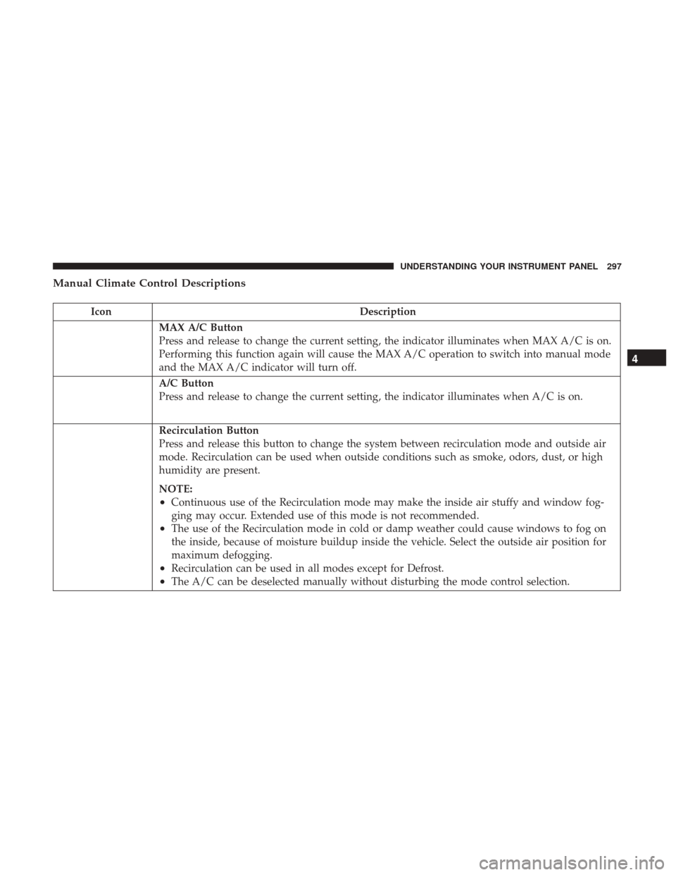
Manual Climate Control Descriptions
IconDescription
MAX A/C Button
Press and release to change the current setting, the indicator illuminates when MAX A/C is on.
Performing this function again will cause the MAX A/C operation to switch into manual mode
and the MAX A/C indicator will turn off.
A/C Button
Press and release to change the current setting, the indicator illuminates when A/C is on.
Recirculation Button
Press and release this button to change the system between recirculation mode and outside air
mode. Recirculation can be used when outside conditions such as smoke, odors, dust, or high
humidity are present.
NOTE:
•Continuous use of the Recirculation mode may make the inside air stuffy and window fog-
ging may occur. Extended use of this mode is not recommended.
•The use of the Recirculation mode in cold or damp weather could cause windows to fog on
the inside, because of moisture buildup inside the vehicle. Select the outside air position for
maximum defogging.
•Recirculation can be used in all modes except for Defrost.
•The A/C can be deselected manually without disturbing the mode control selection.
4
UNDERSTANDING YOUR INSTRUMENT PANEL 297
Page 302 of 530
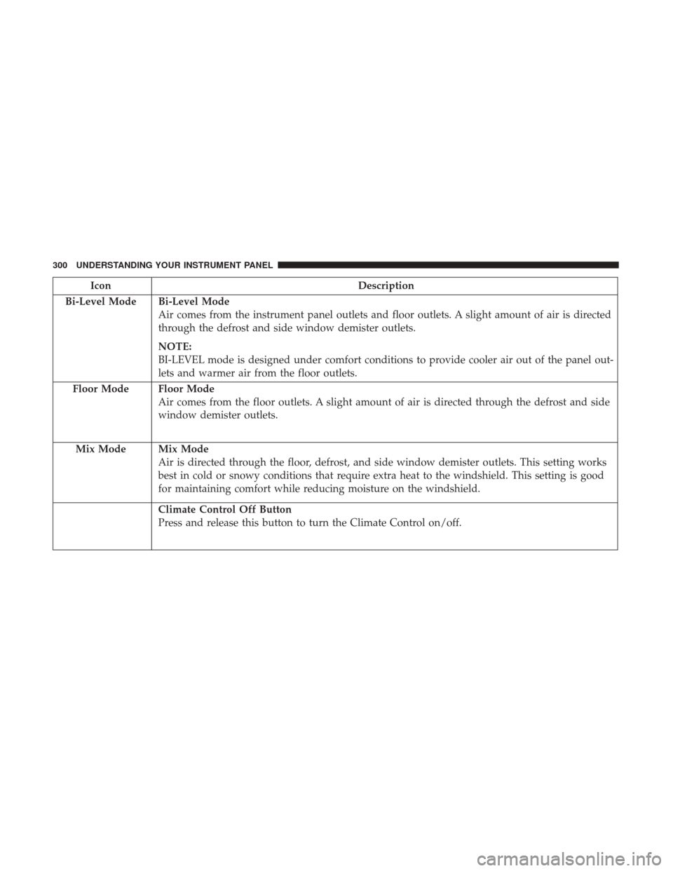
IconDescription
Bi-Level Mode
Bi-Level Mode
Air comes from the instrument panel outlets and floor outlets. A slight amount of air is directed
through the defrost and side window demister outlets.
NOTE:
BI-LEVEL mode is designed under comfort conditions to provide cooler air out of the panel out-
lets and warmer air from the floor outlets.
Floor Mode
Floor Mode
Air comes from the floor outlets. A slight amount of air is directed through the defrost and side
window demister outlets.
Mix Mode
Mix Mode
Air is directed through the floor, defrost, and side window demister outlets. This setting works
best in cold or snowy conditions that require extra heat to the windshield. This setting is good
for maintaining comfort while reducing moisture on the windshield.
Climate Control Off Button
Press and release this button to turn the Climate Control on/off.
300 UNDERSTANDING YOUR INSTRUMENT PANEL