interior lights DODGE HORNET 2023 Owners Manual
[x] Cancel search | Manufacturer: DODGE, Model Year: 2023, Model line: HORNET, Model: DODGE HORNET 2023Pages: 288, PDF Size: 14.2 MB
Page 5 of 288
3
EXTERIOR LIGHTS ...............................................................40Multifunction Lever .................................................... 40
Headlight Switch ......................................................... 40
Daytime Running Lights (DRLs) —
If Equipped .................................................................. 40
High/Low Beam Switch ............................................. 40
Automatic High Beam Headlamp Control —
If Equipped ................................................................. 41
Flash-To-Pass .............................................................. 41
Automatic Headlights — If Equipped ......................... 41
Headlights On Automatically With Wipers —
If Equipped .................................................................. 41
Headlight Delay ........................................................... 41
Lights-On Reminder .................................................... 41
Cornering Lights — If Equipped .................................. 41
Turn Signals ................................................................ 42
Lane Change Assist ................................................... 42
Battery Saver Feature................................................. 42
INTERIOR LIGHTS................................................................42 Interior Courtesy Lights............................................... 42
WINDSHIELD WIPERS AND WASHERS ........................... 44 Windshield Wiper Operation....................................... 44
Rain Sensing Wipers — If Equipped .......................... 45
Rear Window Wiper/Washer ..................................... 46
CLIMATE CONTROLS ..........................................................46 Automatic Climate Control Descriptions And
Functions ..................................................................... 46
Automatic Temperature
Control (ATC) ............................................................... 49
Climate Voice Commands .......................................... 49
Operating Tips ............................................................ 49 INTERIOR STORAGE AND EQUIPMENT ............................ 50
Storage ......................................................................... 50
USB Control .................................................................. 51
Power Outlets — If Equipped ....................................... 52
Wireless Charging Pad —
If Equipped ................................................................... 53
WINDOWS .......................................................................... 55 Power Window Controls............................................... 55
Automatic Window Features ......................................55
Power Window System Initialization........................... 55
Window Lockout Switch ..............................................56
Wind Buffeting ............................................................ 56
POWER SUNROOF — IF EQUIPPED ................................. 56 Opening And Closing The Sunroof ..............................57
Opening And Closing The Power Sunshade ............... 57
Pinch Protect Feature.................................................. 57
Re-Initialization Procedure .......................................... 58
Sunroof Maintenance.................................................. 58
HOOD ................................................................................... 58 Opening The Hood .......................................................58
Closing The Hood ......................................................... 59
LIFTGATE .............................................................................. 59 Unlock/Open The Liftgate ........................................... 59
Lock/Close The Liftgate ..............................................60
Power Liftgate — If Equipped ......................................60
Adjustable Power Liftgate Height ............................... 61
Hands-Free Liftgate — If Equipped ............................ 62
Cargo Area Features.................................................... 63GETTING TO KNOW YOUR
INSTRUMENT PANEL
PREMIUM INSTRUMENT CLUSTER................................... 65 Instrument Cluster Descriptions
b
.......................... 66
INSTRUMENT CLUSTER DISPLAY ..................................... 66 Instrument Cluster Display Location And
Controls........................................................................ 66
Oil Change Reset
b
.................................................. 68
Oil Change Indicator System ...................................... 68
Gear Shift Indicator (GSI) —
If Equipped................................................................... 68
Instrument Cluster Display Menu Items ................... 68
Battery Saver On/Battery Saver Mode Message —
Electrical Load Reduction Actions — If Equipped ...... 70
WARNING LIGHTS AND MESSAGES ................................ 71 Red Warning Lights ..................................................... 71
Yellow Warning Lights ................................................. 73
Yellow Indicator Lights ................................................ 77
Green Indicator Lights................................................. 77
White Indicator Lights ................................................. 78
Blue Indicator Lights ................................................... 78
ONBOARD DIAGNOSTIC SYSTEM — OBD II .................... 78 Onboard Diagnostic System (OBD II)
Cybersecurity ............................................................... 79
EMISSIONS INSPECTION AND MAINTENANCE
PROGRAMS ......................................................................... 79
23_GG_OM_EN_USC_t.book Page 3
Page 15 of 288
13
GETTING TO KNOW YOUR VEHICLE
KEYS
KEY FOBS
Your vehicle is equipped with a key fob which supports
Passive Entry, Remote Keyless Entry (RKE), Keyless
Enter ‘n Go™ (if equipped), Remote Start (if equipped),
and Panic button operation. The key fob allows you to lock
or unlock the doors and liftgate from distances up to
approximately 66 ft (20 m). In some conditions, this
distance can be reduced or increased. The key fob does
not need to be pointed at the vehicle to activate the
system. The key fob also contains an emergency key,
which is stored in the rear of the key fob.
NOTE:
The key fob’s wireless signal may be blocked if the key
fob is located next to a metallic object, mobile phone,
laptop, wireless charging pad, or other electronic
device. This may result in poor performance.
If the key fob’s battery is near depletion, the key fob
performance can be reduced.
With the ignition on and the vehicle moving at 2 mph
(4 km/h), all RKE commands are disabled.
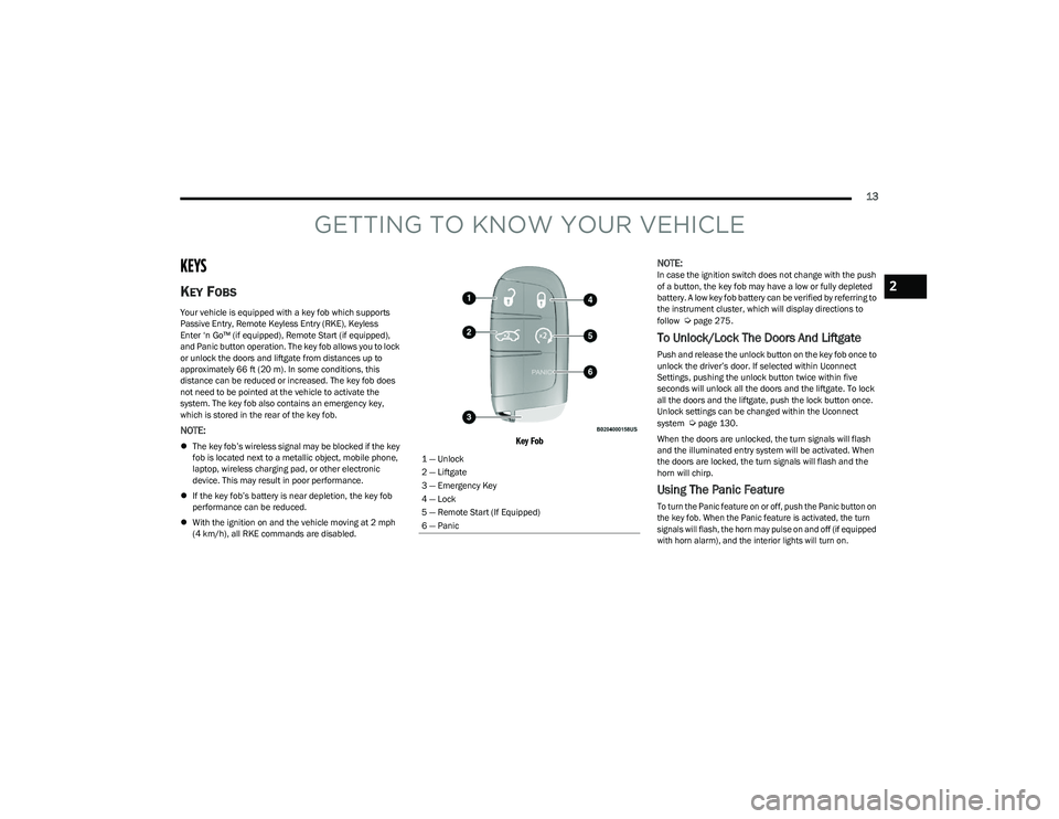
Key Fob
NOTE:
In case the ignition switch does not change with the push
of a button, the key fob may have a low or fully depleted
battery. A low key fob battery can be verified by referring to
the instrument cluster, which will display directions to
follow
Úpage 275.
To Unlock/Lock The Doors And Liftgate
Push and release the unlock button on the key fob once to
unlock the driver’s door. If selected within Uconnect
Settings, pushing the unlock button twice within five
seconds will unlock all the doors and the liftgate. To lock
all the doors and the liftgate, push the lock button once.
Unlock settings can be changed within the Uconnect
system
Úpage 130.
When the doors are unlocked, the turn signals will flash
and the illuminated entry system will be activated. When
the doors are locked, the turn signals will flash and the
horn will chirp.
Using The Panic Feature
To turn the Panic feature on or off, push the Panic button on
the key fob. When the Panic feature is activated, the turn
signals will flash, the horn may pulse on and off (if equipped
with horn alarm), and the interior lights will turn on.
1 — Unlock
2 — Liftgate
3 — Emergency Key
4 — Lock
5 — Remote Start (If Equipped)
6 — Panic
2
23_GG_OM_EN_USC_t.book Page 13
Page 16 of 288
14GETTING TO KNOW YOUR VEHICLE
The Panic feature will stay on for three minutes unless you
turn it off by either pushing the Panic button a second time
or driving the vehicle at a speed of 15 mph (24 km/h) or
greater.
NOTE:
The interior lights will turn off if you place the ignition in
the ON/RUN position while the Panic feature is
activated. However, the exterior lights and horn
(if equipped with horn alarm) will remain on.
You may need to be closer than 66 ft (20 m) from the
vehicle when using the key fob to turn off the Panic
feature due to the radio frequency noises emitted by
the system.
Key Left Vehicle Feature
If a valid key fob is no longer detected inside the vehicle
while the vehicle’s ignition system is in the ON/RUN or
START position, the message “Key Fob Has Left The
Vehicle” will be shown in the instrument cluster display
and an interior chime will sound. An exterior audible and
visual alert will also be activated to warn the driver.
The vehicle’s horn will rapidly chirp three times along with
a single flash of the vehicle’s exterior lights.
NOTE:
The doors have to be open and then closed in order for
the vehicle to detect a key fob. The Key Left Vehicle
feature will activate when the first door is closed and
no key fob is detected in the vehicle. If the warning has
been activated, and the other doors are closed, no
other warnings will be issued.
These alerts will not be activated in situations where
either the vehicle’s engine is left running with the key
fob inside, or the key fob’s wireless signals are blocked.
Using The Key Fob To Open/Close Vehicle
Windows — If Equipped
To Open The Windows
From outside of the vehicle, push the unlock button on the
key fob twice, and hold for several seconds. All vehicle
door windows will open.
To Close The Windows
From outside of the vehicle, push the lock button on the
key fob twice, and hold for several seconds. All vehicle
door windows will close.
NOTE:
This feature is enabled through Uconnect Settings Úpage 130.
Vehicle must be equipped with front and rear auto up/
down windows.
Replacing The Battery In The Key Fob
The replacement battery is one CR2032 battery.
NOTE:
Customers are recommended to use a battery
obtained from Mopar®. Aftermarket coin battery
dimensions may not meet the original OEM coin battery
dimensions.
Perchlorate material — special handling may apply. See
www.dtsc.ca.gov/hazardouswaste/perchlorate for
further information.
Do not touch the battery terminals that are on the back
housing or the printed circuit board.
To replace the key fob battery, proceed as follows:
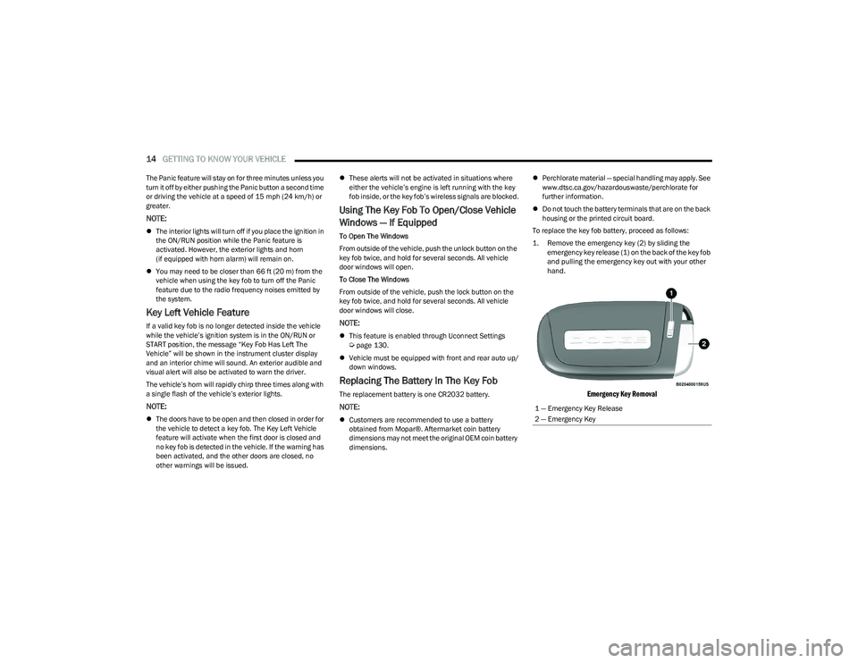
1. Remove the emergency key (2) by sliding the emergency key release (1) on the back of the key fob
and pulling the emergency key out with your other
hand.
Emergency Key Removal
1 — Emergency Key Release
2 — Emergency Key
23_GG_OM_EN_USC_t.book Page 14
Page 42 of 288
40GETTING TO KNOW YOUR VEHICLE
EXTERIOR LIGHTS
MULTIFUNCTION LEVER
Multifunction Lever
The multifunction lever controls the operation of the
turn signals, headlight beam selection and passing lights.
The multifunction lever is located on the left side of the
steering column.
HEADLIGHT SWITCH
The headlight switch is located on the left side of the
instrument panel. This switch controls the operation of the
headlights, parking lights, automatic headlights (if
equipped), instrument panel lights, and interior lights.
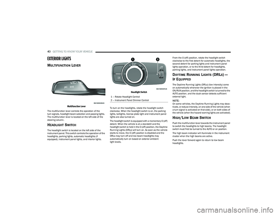
Headlight Switch
To turn on the headlights, rotate the headlight switch
clockwise. When the headlight switch is on, the parking
lights, taillights, license plate light and instrument panel
lights are also turned on.
The headlight switch is equipped with a momentary O (off)
detent. When the vehicle is at a standstill and the
headlight switch is held in the O (off) position, the Daytime
Running Lights (DRLs) will turn on. As soon as the vehicle
starts to move, the O (off) position is disabled and the
DRLs may turn off and low beam headlights may
automatically turn on based on exterior ambient
light levels. From the O (off) position, rotate the headlight switch
clockwise to the first detent for automatic headlights, the
second detent for parking lights and instrument panel
lights operation, or to the third detent for headlights,
parking lights, and instrument panel lights operation.
DAYTIME RUNNING LIGHTS (DRLS) —
I
F EQUIPPED
The Daytime Running Lights (DRLs) (low intensity) come
on automatically whenever the ignition is placed in the
ON/RUN position, and the headlight switch is turned to the
AUTO position, and the dusk sensor detects sufficient
external light.
NOTE:On some vehicles, the Daytime Running Lights may deac -
tivate, or reduce intensity, on one side of the vehicle (when
a turn signal is activated on that side), or on both sides of
the vehicle (when the hazard warning lights are activated).
HIGH/LOW BEAM SWITCH
Push the multifunction lever towards the instrument panel
to switch the headlights to high beams. The headlight
switch must first be turned to the AUTO or on position.
The high beam indicator will illuminate in the instrument
cluster when the high beams are active.
Push the lever forward again to return to low beam
headlights.
1 — Rotate Headlight Control
2 — Instrument Panel Dimmer Control
23_GG_OM_EN_USC_t.book Page 40
Page 44 of 288
42GETTING TO KNOW YOUR VEHICLE
TURN SIGNALS
Move the multifunction lever up or down to activate the
turn signals. The arrows on each side of the instrument
cluster display flash to show proper operation.
Once the turn signal lever is activated, it will return to its
original position. To cancel the turn signal action, the lever
must be moved again or the turn in that direction must be
completed.
NOTE:If either light remains on and does not flash, or there is a
very fast flash rate, check for a defective outside light
bulb.
LANE CHANGE ASSIST
Lightly push the multifunction lever up or down, without
moving beyond the detent, and the turn signal will flash
three times then automatically turn off.
To turn off the flashing before the end of the cycle, move
the lever in the opposite direction until the first click
(about half way).
BATTERY SAVER FEATURE
To protect the battery, if the headlight switch is left in the
low beam or parking lights position when the ignition is
placed in the OFF position, the lights are deactivated after
eight minutes. The lights can also be turned off manually
by rotating the headlight switch to the O (off) position.
INTERIOR LIGHTS
INTERIOR COURTESY LIGHTS
Courtesy and dome lights are turned on when the front
doors are opened.
To protect the battery, the interior lights will turn off
automatically 15 minutes after the ignition is placed in the
OFF position, and no other activity in the vehicle has
occurred. This will occur if the interior lights were turned
on manually or are on because a door is open. This
includes the glove compartment light and the cargo area
light. To restore interior light operation, either place the
ignition in the ON/RUN position, or push the light switch on
and then back off.
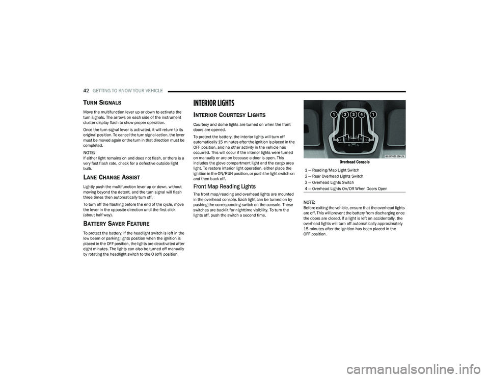
Front Map Reading Lights
The front map/reading and overhead lights are mounted
in the overhead console. Each light can be turned on by
pushing the corresponding switch on the console. These
switches are backlit for nighttime visibility. To turn the
lights off, push the switch a second time.
Overhead Console
NOTE:
Before exiting the vehicle, ensure that the overhead lights
are off. This will prevent the battery from discharging once
the doors are closed. If a light is left on accidentally, the
overhead lights will turn off automatically approximately
15 minutes after the ignition has been placed in the
OFF position. 1 — Reading/Map Light Switch
2 — Rear Overhead Lights Switch
3 — Overhead Lights Switch
4 — Overhead Lights On/Off When Doors Open
23_GG_OM_EN_USC_t.book Page 42
Page 45 of 288
GETTING TO KNOW YOUR VEHICLE43
Overhead Light Timing
On certain models, to assist getting in and out of the
vehicle at night or in poorly-lit areas, two timed modes
have been provided.
Timing While Getting Into The Vehicle
The overhead lights turn on according to the following
modes:
Will illuminate for approximately three minutes when
the doors are unlocked.
Will illuminate for approximately three minutes when
one of the doors is opened.
Will illuminate for approximately 27 seconds when
each individual door is closed and switch off simultane -
ously when the doors are locked.
Timing is interrupted when the ignition is placed in the
ON/RUN position.
Three Modes Are Available For Turning Off Overhead
Lighting:
When all doors are closed after entering the vehicle,
the three-minute timer will stop and a seconds timer
will start for the interior lights. This timing will stop
when the ignition is placed in the ON/RUN position.
When doors are locked (either with key fob or with the
emergency key inserted in driver side door), the over -
head light turns off.
The interior lights will turn off after 15 minutes to
preserve the battery. Timing While Getting Out Of The Vehicle
After placing the ignition in the OFF position, the overhead
lights will turn on as follows:
For a few seconds after the engine stops.
For approximately three minutes when one of the doors
is opened.
For several seconds when the last door is closed.
The timing stops automatically when the doors are locked.
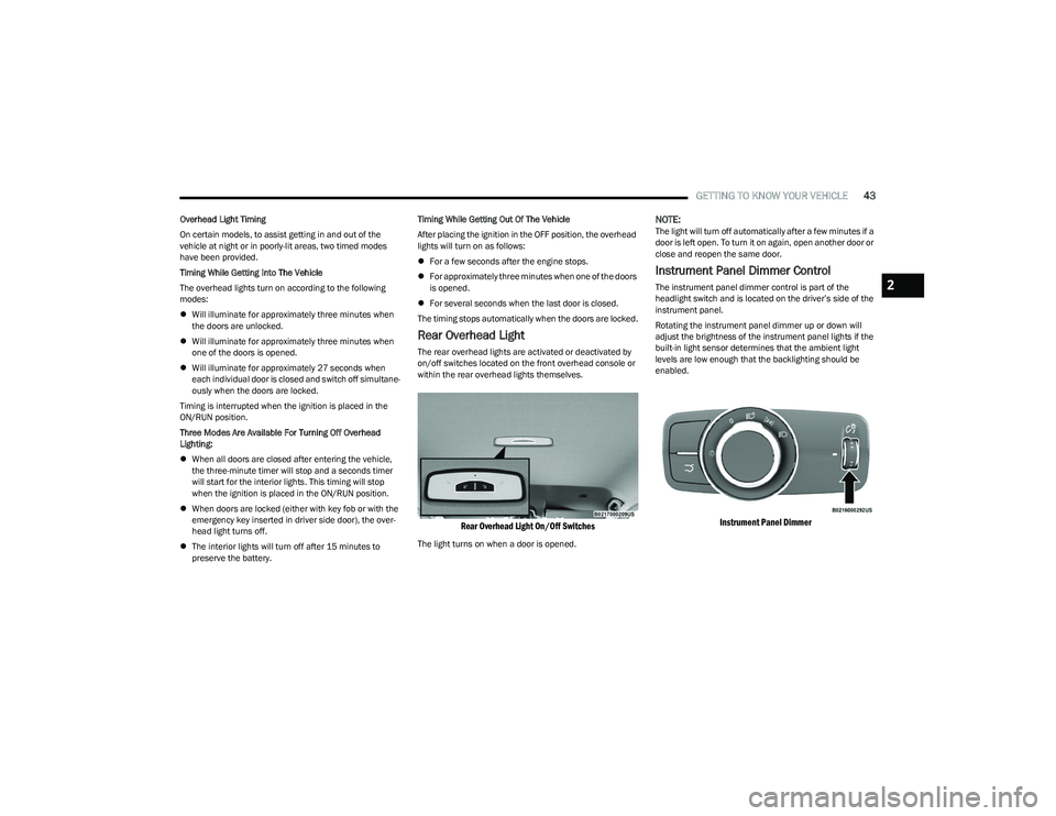
Rear Overhead Light
The rear overhead lights are activated or deactivated by
on/off switches located on the front overhead console or
within the rear overhead lights themselves.
Rear Overhead Light On/Off Switches
The light turns on when a door is opened.
NOTE:The light will turn off automatically after a few minutes if a
door is left open. To turn it on again, open another door or
close and reopen the same door.
Instrument Panel Dimmer Control
The instrument panel dimmer control is part of the
headlight switch and is located on the driver’s side of the
instrument panel.
Rotating the instrument panel dimmer up or down will
adjust the brightness of the instrument panel lights if the
built-in light sensor determines that the ambient light
levels are low enough that the backlighting should be
enabled.
Instrument Panel Dimmer
2
23_GG_OM_EN_USC_t.book Page 43
Page 46 of 288
44GETTING TO KNOW YOUR VEHICLE
Interior Ambient Lighting — If Equipped
The brightness of the interior passenger compartment
lights can be adjusted through Uconnect Settings
Úpage 130.
The lights can be adjusted to seven different levels of
brightness.
Battery Saver Feature
To protect the battery, the interior lights will turn off
automatically 15 minutes after the ignition switch is
placed in the OFF position. This will occur if the interior
lights were switched on manually or are on because a
door is open.
WINDSHIELD WIPERS AND WASHERS
The windshield wiper/washer controls are located on the
windshield wiper/washer lever on the right side of the
steering column. The front wipers are operated by rotating
a switch, located on the end of the lever. For information
on the rear wiper/washer, see
Úpage 46.
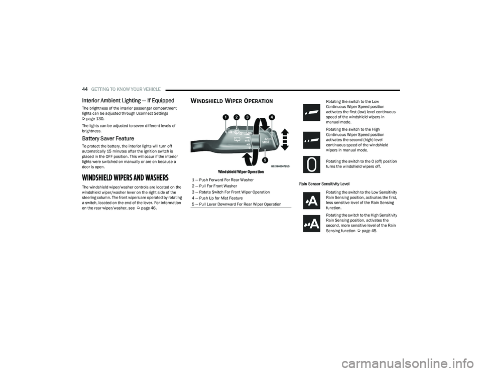
WINDSHIELD WIPER OPERATION
Windshield Wiper Operation
Rain Sensor Sensitivity Level
1 — Push Forward For Rear Washer
2 — Pull For Front Washer
3 — Rotate Switch For Front Wiper Operation
4 — Push Up for Mist Feature
5 — Pull Lever Downward For Rear Wiper Operation
Rotating the switch to the Low
Continuous Wiper Speed position
activates the first (low) level continuous
speed of the windshield wipers in
manual mode.
Rotating the switch to the High
Continuous Wiper Speed position
activates the second (high) level
continuous speed of the windshield
wipers in manual mode.
Rotating the switch to the O (off) position
turns the windshield wipers off.
Rotating the switch to the Low Sensitivity
Rain Sensing position, activates the first,
less sensitive level of the Rain Sensing
function.
Rotating the switch to the High Sensitivity
Rain Sensing position, activates the
second, more sensitive level of the Rain
Sensing function
Úpage 45.
23_GG_OM_EN_USC_t.book Page 44
Page 72 of 288
70GETTING TO KNOW YOUR INSTRUMENT PANEL
DRIVER ASSIST
The instrument cluster display displays the current
Adaptive Cruise Control (ACC) and Lane Keep Assist (LKA)
system settings. The information displayed depends on
ACC system status.
The Instrument Cluster Display shows the status and
settings of the driving assistance Adaptive Cruise Control,
Lane Keep Assist and Active Driving Assist systems. Any
instant notifications are displayed via a pop-up screen.
The instrument cluster display displays the current LKA
system settings. The information displayed depends on
Lane Keep Assist system status and the conditions that
need to be met
Úpage 113.
STORED MESSAGES
Turn the Thumbwheel up and down until the Stored
Messages menu option is highlighted. Press the
Thumbwheel to enter and exit the Stored Messages.
Messages shown on the display via popup screens are
stored as long as they remain valid. You can view them
later in the central area of the “Messages” screen.
If multiple messages are present:
Press the Thumbwheel to access the message list.
Scroll through the messages by turning the Thumb -
wheel up or down. The presence or previous or next
message is indicated by gray dots.
BATTERY SAVER ON/BATTERY SAVER
M
ODE MESSAGE — ELECTRICAL LOAD
R
EDUCTION ACTIONS — IF EQUIPPED
This vehicle is equipped with an Intelligent Battery Sensor
(IBS) to perform additional monitoring of the electrical
system and status of the vehicle battery.
In cases when the IBS detects charging system failure, or
the vehicle battery conditions are deteriorating, electrical
load reduction actions will take place to extend the driving
time and distance of the vehicle. This is done by reducing
power to or turning off non-essential electrical loads.
Load reduction is only active when the engine is running.
It will display a message if there is a risk of battery
depletion to the point where the vehicle may stall due to
lack of electrical supply, or will not restart after the current
drive cycle.
These messages indicate the vehicle battery has a low
state of charge and continues to lose electrical charge at
a rate that the charging system cannot sustain.
NOTE:
The charging system is independent from load reduc -
tion. The charging system performs a diagnostic on the
charging system continuously.
If the Battery Charge Warning Light is on it may indicate
a problem with the charging system
Úpage 72. The electrical loads that may be switched off (if equipped),
and vehicle functions which can be effected by load
reduction:
Heated Seat/Vented Seats/Heated Wheel
Heated/Cooled Cup Holders — If Equipped
Rear Defroster And Heated Mirrors
HVAC System
150W Power Inverter System
Audio and Telematics System
Loss of the battery charge may indicate one or more of the
following conditions:
The charging system cannot deliver enough electrical
power to the vehicle system because the electrical
loads are larger than the capability of charging system.
The charging system is still functioning properly.
Turning on all possible vehicle electrical loads (e.g.
HVAC to max settings, exterior and interior lights, over -
loaded power outlets +12 Volts, 150W, USB ports)
during certain driving conditions (city driving, towing,
frequent stopping).
Installing options like additional lights, upfitter elec -
trical accessories, audio systems, alarms and similar
devices.
Unusual driving cycles (short trips separated by long
parking periods).
The vehicle was parked for an extended period of time
(weeks, months).
23_GG_OM_EN_USC_t.book Page 70
Page 73 of 288
GETTING TO KNOW YOUR INSTRUMENT PANEL71
The battery was recently replaced and was not charged
completely.
The battery was discharged by an electrical load left on
when the vehicle was parked.
The battery was used for an extended period with the
engine not running to supply radio, lights, chargers,
+12 Volts portable appliances like vacuum cleaners,
game consoles and similar devices.
What to do when an electrical load reduction action
message is present (“Battery Saver On” or
“Battery Saver Mode”)
During a trip:
Reduce power to unnecessary loads if possible:
Turn off redundant lights (interior or exterior)
Check what may be plugged into power outlets
+12 Volts, 150W, USB ports
Check HVAC settings (blower, temperature)
Check the audio settings (volume)
After a trip:
Check if any aftermarket equipment was installed
(additional lights, upfitter electrical accessories,
audio systems, alarms) and review specifications if any
(load and Ignition Off Draw currents).
Evaluate the latest driving cycles (distance, driving
time and parking time).
The vehicle should have service performed if the
message is still present during consecutive trips and
the evaluation of the vehicle and driving pattern did not
help to identify the cause.WARNING LIGHTS AND MESSAGES
The warning/indicator lights will illuminate in the
instrument panel together with a dedicated message and/
or acoustic signal when applicable. These indications are
indicative and precautionary and as such must not be
considered as exhaustive and/or alternative to the
information contained in the Owner’s Manual, which you
are advised to read carefully in all cases. Always refer to
the information in this chapter in the event of a failure
indication. All active telltales will display first if applicable.
The system check menu may appear different based upon
equipment options and current vehicle status. Some
telltales are optional and may not appear.
RED WARNING LIGHTS
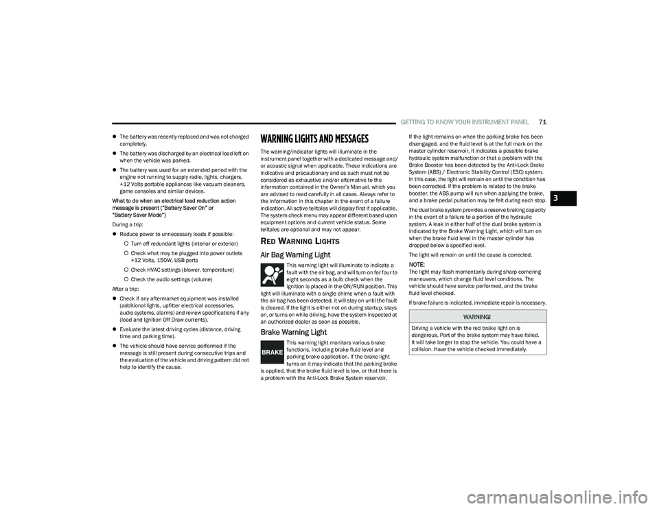
Air Bag Warning Light
This warning light will illuminate to indicate a
fault with the air bag, and will turn on for four to
eight seconds as a bulb check when the
ignition is placed in the ON/RUN position. This
light will illuminate with a single chime when a fault with
the air bag has been detected, it will stay on until the fault
is cleared. If the light is either not on during startup, stays
on, or turns on while driving, have the system inspected at
an authorized dealer as soon as possible.
Brake Warning Light
This warning light monitors various brake
functions, including brake fluid level and
parking brake application. If the brake light
turns on it may indicate that the parking brake
is applied, that the brake fluid level is low, or that there is
a problem with the Anti-Lock Brake System reservoir. If the light remains on when the parking brake has been
disengaged, and the fluid level is at the full mark on the
master cylinder reservoir, it indicates a possible brake
hydraulic system malfunction or that a problem with the
Brake Booster has been detected by the Anti-Lock Brake
System (ABS) / Electronic Stability Control (ESC) system.
In this case, the light will remain on until the condition has
been corrected. If the problem is related to the brake
booster, the ABS pump will run when applying the brake,
and a brake pedal pulsation may be felt during each stop.
The dual brake system provides a reserve braking capacity
in the event of a failure to a portion of the hydraulic
system. A leak in either half of the dual brake system is
indicated by the Brake Warning Light, which will turn on
when the brake fluid level in the master cylinder has
dropped below a specified level.
The light will remain on until the cause is corrected.
NOTE:The light may flash momentarily during sharp cornering
maneuvers, which change fluid level conditions. The
vehicle should have service performed, and the brake
fluid level checked.
If brake failure is indicated, immediate repair is necessary.
WARNING!
Driving a vehicle with the red brake light on is
dangerous. Part of the brake system may have failed.
It will take longer to stop the vehicle. You could have a
collision. Have the vehicle checked immediately.
3
23_GG_OM_EN_USC_t.book Page 71
Page 143 of 288
MULTIMEDIA141
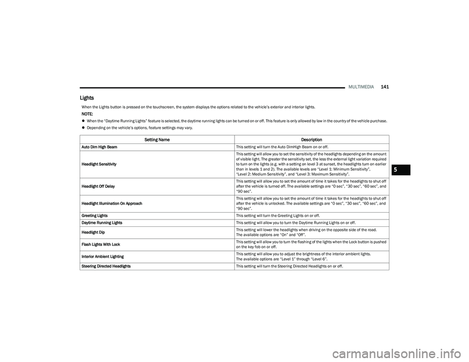
Lights
When the Lights button is pressed on the touchscreen, the system displays the options related to the vehicle’s exterior and interior lights.
NOTE:
When the “Daytime Running Lights” feature is selected, the daytime running lights can be turned on or off. This feature is only allowed by law in the country of the vehicle purchase.
Depending on the vehicle’s options, feature settings may vary.
Setting Name Description
Auto Dim High Beam This setting will turn the Auto DimHigh Beam on or off.
Headlight Sensitivity This setting will allow you to set the sensitivity of the headlights depending on the amount
of visible light. The greater the sensitivity set, the less the external light variation required
to turn on the lights (e.g. with a setting on level 3 at sunset, the headlights turn on earlier
than in levels 1 and 2). The available levels are “Level 1: Minimum Sensitivity”,
“Level 2: Medium Sensitivity”, and “Level 3: Maximum Sensitivity”.
Headlight Off Delay This setting will allow you to set the amount of time it takes for the headlights to shut off
after the vehicle is turned off. The available settings are “0 sec”, “30 sec”, “60 sec”, and
“90 sec”.
Headlight Illumination On Approach This setting will allow you to set the amount of time it takes for the headlights to shut off
after the vehicle is unlocked. The available settings are “0 sec”, “30 sec”, “60 sec”, and
“90 sec”.
Greeting Lights This setting will turn the Greeting Lights on or off.
Daytime Running Lights This setting will allow you to turn the Daytime Running Lights on or off.
Headlight Dip This setting will lower the headlights when driving on the opposite side of the road.
The available options are “On” and “Off”.
Flash Lights With Lock This setting will allow you to turn the flashing of the lights when the Lock button is pushed
on the key fob on or off.
Interior Ambient Lighting This setting will allow you to adjust the brightness of the interior ambient lights.
The available options are “Level 1” through “Level 6”.
Steering Directed Headlights This setting will turn the Steering Directed Headlights on or off.
5
23_GG_OM_EN_USC_t.book Page 141