lights DODGE JOURNEY 2014 1.G User Guide
[x] Cancel search | Manufacturer: DODGE, Model Year: 2014, Model line: JOURNEY, Model: DODGE JOURNEY 2014 1.GPages: 124, PDF Size: 3.37 MB
Page 3 of 124
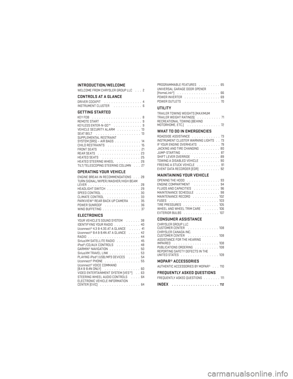
INTRODUCTION/WELCOME
WELCOME FROM CHRYSLER GROUP LLC . . . 2
CONTROLS AT A GLANCE
DRIVER COCKPIT................4
INSTRUMENT CLUSTER ............6
GETTING STARTED
KEYFOB .....................8
REMOTE START.................9
KEYLESS ENTER-N-GO™ ............9
VEHICLE SECURITY ALARM ..........13
SEATBELT ...................13
SUPPLEMENTAL RESTRAINT
SYSTEM (SRS) — AIR BAGS ...........14
CHILD RESTRAINTS ..............15
FRONT SEATS .................21
REARSEATS ..................23
HEATEDSEATS ................25
HEATED STEERING WHEEL ..........26
TILT/TELESCOPING STEERING COLUMN . . . 27
OPERATING YOUR VEHICLE
ENGINE BREAK-IN RECOMMENDATIONS . . . 28
TURN SIGNAL/WIPER/WASHER/HIGH BEAM
LEVER ......................28
HEADLIGHT SWITCH ..............29
SPEED CONTROL ................30
CLIMATE CONTROL ..............33
PARKVIEW® REAR BACK-UP CAMERA ....35
POWER SUNROOF ...............36
WIND BUFFETING ................37
ELECTRONICS
YOUR VEHICLE'S SOUND SYSTEM ......38
IDENTIFYING YOUR RADIO ...........40
Uconnect® 4.3 & 4.3S AT A GLANCE .....41
Uconnect® 8.4 & 8.4N AT A GLANCE .....42
RADIO ......................44
SiriusXM SATELLITE RADIO ..........45
iPod®/CD/AUX CONTROLS ..........48
GARMIN® NAVIGATION .............50
SiriusXM TRAVEL LINK .............53
PLAYING iPod®/USB/MP3 DEVICES .....54
Uconnect® PHONE ...............55
Uconnect® VOICE COMMAND
(8.4&8.4NONLY) ...............60
VIDEO ENTERTAINMENT SYSTEM (VES™) . . 63
STEERING WHEEL AUDIO CONTROLS ....64
ELECTRONIC VEHICLE INFORMATION
CENTER (EVIC) .................64 PROGRAMMABLE FEATURES
.........65
UNIVERSAL GARAGE DOOR OPENER
(HomeLink®) ..................66
POWER INVERTER ...............69
POWER OUTLETS ...............70
UTILITY
TRAILER TOWING WEIGHTS (MAXIMUM
TRAILERWEIGHTRATINGS) ..........71
RECREATIONAL TOWING (BEHIND
MOTORHOME, ETC.) ..............72
WHAT TO DO IN EMERGENCIES
ROADSIDE ASSISTANCE ............73
INSTRUMENT CLUSTER WARNING LIGHTS . . 73
IF YOUR ENGINE OVERHEATS .........79
JACKING AND TIRE CHANGING ........80
JUMP-STARTING ................87
SHIFT LEVER OVERRIDE ...........89
TOWING A DISABLED VEHICLE ........90
FREEING A STUCK VEHICLE ..........91
EVENT DATA RECORDER (EDR) ........92
MAINTAINING YOUR VEHICLE
OPENING THE HOOD..............93
ENGINE COMPARTMENT ...........94
FLUIDS AND CAPACITIES ...........96
MAINTENANCE SCHEDULE ..........98
MAINTENANCE RECORD ...........102
FUSES .....................103
TIRE PRESSURES ...............105
WHEEL AND WHEEL TRIM CARE ......106
EXTERIOR BULBS ...............107
CONSUMER ASSISTANCE
CHRYSLER GROUP LLC
CUSTOMER CENTER .............108
CHRYSLER CANADA INC.
CUSTOMER CENTER .............108
ASSISTANCE FOR THE HEARING
IMPAIRED ...................108
PUBLICATIONS ORDERING ..........108
REPORTING SAFETY DEFECTS IN THE
UNITEDSTATES ................109
MOPAR® ACCESSORIES
AUTHENTIC ACCESSORIES BY MOPAR® . . . 110
FREQUENTLY ASKED QUESTIONS
FREQUENTLY ASKED QUESTIONS .......111
INDEX....................112
TABLE OF CONTENTS
Page 8 of 124
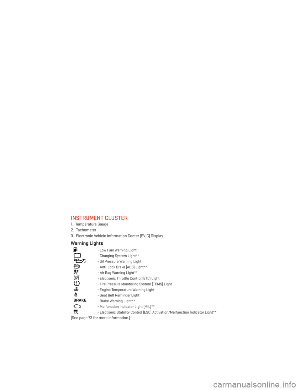
INSTRUMENT CLUSTER
1. Temperature Gauge
2. Tachometer
3. Electronic Vehicle Information Center (EVIC) Display
Warning Lights
- Low Fuel Warning Light
- Charging System Light**
- Oil Pressure Warning Light
- Anti-Lock Brake (ABS) Light**
- Air Bag Warning Light**
- Electronic Throttle Control (ETC) Light
- Tire Pressure Monitoring System (TPMS) Light
- Engine Temperature Warning Light
- Seat Belt Reminder Light
BRAKE- Brake Warning Light**
- Malfunction Indicator Light (MIL)**
- Electronic Stability Control (ESC) Activation/Malfunction Indicator Light**
(See page 73 for more information.)
CONTROLS AT A GLANCE
6
Page 31 of 124
Front Wipers
Intermittent, Low And High Operation
• Rotate the end of the lever to the first detent position for one of five intermittent settings,the second detent for low wiper operation and the third detent for high wiper operation.
Washer Operation
• Push the end of the lever in to the second detent and release.
Mist
• Push the end of the lever in to the first detent and release.
NOTE:
The mist feature does not activate the washer pump; therefore, no washer fluid will be
sprayed on the windshield. The wash function must be activated in order to spray the
windshield with washer fluid.
Rear Wiper
Wiper Operation
• Rotate the center portion of the lever forward to the first detent for rear wiper operation.
Washer Operation
• Rotate the center portion of the lever past the first detent to activate the rear washer.
HEADLIGHT SWITCH
Automatic Headlights/Parking
Lights/Headlights
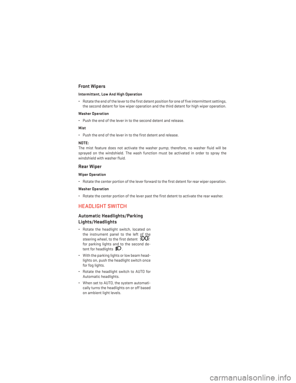
• Rotate the headlight switch, located on the instrument panel to the left of the
steering wheel, to the first detent
for parking lights and to the second de-
tent for headlights
.
• With the parking lights or low beam head- lights on, push the headlight switch once
for fog lights.
• Rotate the headlight switch to AUTO for Automatic headlights.
• When set to AUTO, the system automati- cally turns the headlights on or off based
on ambient light levels.
OPERATING YOUR VEHICLE
29
Page 32 of 124
Instrument Panel Dimmer
• Rotate the dimmer control to the extreme bottom position to fully dim the instrumentpanel lights and prevent the interior lights from illuminating when a door is opened.
• Rotate the dimmer control up to increase the brightness of the instrument panel when the parking lights or headlights are on.
• Rotate the dimmer control up to the next detent position to fully brighten the odometer and radio when the parking lights or headlights are on.
• Rotate the dimmer control up to the last detent position to turn on the interior lighting.
• If your vehicle is equipped with a touchscreen, the dimming is programmable through the Uconnect® system. Refer to “Uconnect® Settings ” in “Understanding Your Instrument
Panel” in the Owner's Manual on the DVD for further details.
Door/Map Pocket Lights
• Rotate the Door/Map Pocket control up or down to increase or decrease the brightness ofthe door handle and map pocket lighting when the parking lights or headlights are on.
SPEED CONTROL
The Speed Control switches are located on the steering wheel.
Cruise ON/OFF
• Push the ON/OFF button to activate theSpeed Control.
CRUISE
will appear on the instrument
cluster to indicate the Speed Control is on.
• Push the ON/OFF button a second time to turn the system off.
SET
• With the Speed Control on, push and re-lease the SET – button to set a desired
speed.
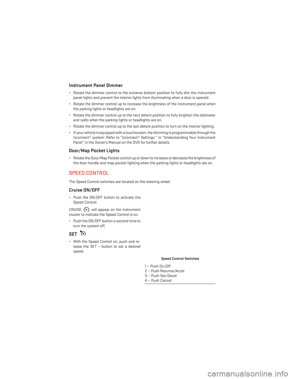
Speed Control Switches
1 — Push On/Off
2 — Push Resume/Accel
3 — Push Set/Decel
4 — Push Cancel
OPERATING YOUR VEHICLE
30
Page 67 of 124
Compass Calibration
This compass is self-calibrating, which eliminates the need to set the compass manually.
When the vehicle is new, the compass may appear erratic and the EVIC will display “CAL”
until the compass is calibrated.
You may also calibrate the compass by completing one or more 360 degree turns (in an area
free from large metal or metallic objects) until the “CAL” message displayed in the EVIC
turns off. The compass will now function normally.
PROGRAMMABLE FEATURES
Electronic Vehicle Information Center (EVIC) — If Equipped
• The EVIC can be used to view or change the following settings. Press the UPor
DOWN
button until System Setup displays, then press the SELECTbutton. Scroll
through the settings using the UP or DOWN buttons. Press the SELECT
button to
change the setting. Press the BACK button to scroll back to a previous menu or sub
menu.
• Fuel Economy • Average Fuel Economy
• Distance To Empty (DTE)
• Miles Per Gallon (MPG) • Trip Info
• Trip A
• Trip B
• Elapsed Time
• Vehicle Speed • Tire PSI
• Messages •
Vehicle Info (Customer Information
Features)
Uconnect® 4.3 Customer Programmable Features
• The Uconnect® 4.3 system allows you to access Customer Programmable feature set- tings such as Display, Clock, Safety/Assistance, Lights, Doors & Locks, Heated Seats,
Engine Off Operation, Compass Settings, Audio, Phone/ Bluetooth® and SIRIUS Setup
through hard-keys and soft-keys.
• Press the “Settings” hard-key to on the right side of the unit to access the Settings screen, use the “Page Up/Down” soft-keys to scroll through the following settings. The
following feature settings are available:
• Display • Auto On Comfort & Remote Start
• Clock • Engine Off Options
• Safety/Assistance • Audio
• Lights • Phone/Bluetooth®
• Doors & Locks • SIRIUS Setup
ELECTRONICS
65
Page 68 of 124
Uconnect® 8.4 Customer Programmable Features
• The Uconnect® 8.4 system allows you to access Customer Programmable feature set-tings such as Display, Clock, Safety/Assistance, Lights, Doors & Locks, Heated Seats,
Engine Off Operation, Compass Settings, Audio, Phone/Bluetooth® and SIRIUS Setup
through soft-keys.
• Touch the “More” soft-key on the bottom of the screen, then touch the “Settings” soft-key to access the Settings screen. When making a selection, scroll up or down until
the preferred setting is highlighted, then press and release the preferred setting until a
check-mark appears next to the setting, showing that setting has been selected.
The following feature settings are available:
• Display • Auto On Comfort & Remote Start
• Clock • Engine Off Options
• Safety/Assistance • Audio
• Lights • Phone/Bluetooth®
• Doors & Locks • SIRIUS Setup
UNIVERSAL GARAGE DOOR OPENER (HomeLink®)
• HomeLink® replaces up to three hand-held transmitters that operate devices such as
garage door openers, motorized gates, lighting or home security systems. The
HomeLink® unit is powered by your vehicles 12 Volt battery.
• The HomeLink® buttons that are located in the overhead console or sunvisor designate the three different HomeLink® channels.
• The HomeLink® indicator is located above the center button.
Before You Begin Programming
HomeLink®
Ensure that your vehicle is parked outside of
the garage before you begin programming.
For efficient programming and accurate
transmission of the radio-frequency signal,
it is recommended that a new battery be
placed in the hand-held transmitter of the
device that is being programmed to the
HomeLink® system.
Erase all channels before you begin pro-
gramming. To erase the channels, place the
ignition switch into the ON/RUN position,
then press and hold the two outside HomeLink® buttons (I and III) for up to 20 seconds or
until the red indicator flashes.
ELECTRONICS
66
Page 75 of 124
ROADSIDE ASSISTANCE
Dial toll-free 1-800-521-2779 for U.S. Residents or 1-800-363-4869 for Canadian Residents.
• Provide your name, vehicle identification number, license plate number, and your loca-tion, including the telephone number from which you are calling.
• Briefly describe the nature of the problem and answer a few simple questions.
• You will be given the name of the service provider and an estimated time of arrival. If you feel you are in an “unsafe situation”, please let us know. With your consent, we will
contact local police or safety authorities.
INSTRUMENT CLUSTER WARNING LIGHTS
- Charging System Light
This light shows the status of the electrical charging system. If the charging system light
remains on, it means that the vehicle is experiencing a problem with the charging system.
We recommend you do not continue driving if the charging system light is on. Have the
vehicle serviced immediately.
- Oil Pressure Warning Light
This light indicates low engine oil pressure. If the light turns on while driving, stop the
vehicle and shut off the engine as soon as possible. A chime will sound for four minutes
when this light turns on.
We recommend you do not operate the vehicle or engine damage will occur. Have the
vehicle serviced immediately.
- Anti-Lock Brake (ABS) Light
This light monitors the Anti-Lock Brake System (ABS). The light will turn on when the
ignition switch is turned to the ON/RUN position and may stay on for as long as four
seconds.
If the ABS light remains on or turns on while driving, it indicates that the Anti-Lock portion
of the brake system is not functioning and that service is required. However, the conven-
tional brake system will continue to operate normally if the BRAKE warning light is not on.
If the ABS light is on, the brake system should be serviced as soon as possible to restore the
benefits of Anti-Lock brakes. If the ABS light does not turn on when the ignition switch is
turned to the ON/RUN position, have the light inspected by an authorized dealer.
WHAT TO DO IN EMERGENCIES
73
Page 80 of 124
- High Beam Indicator
Indicates that headlights are on high beam.
- Front Fog Light Indicator
This indicator will illuminate when the front fog lights are on.
- Vehicle Security Light
This light will flash rapidly for approximately 15 seconds when the vehicle theft alarm is
arming. The light will flash at a slower speed continuously after the alarm is set. The
security light will also come on for about three seconds when the ignition is first turned on.
- Electronic Speed Control ON Indicator
This indicator will illuminate when the electronic speed control has been activated to the
“ON” position.
- Electronic Speed Control SET Indicator
This indicator will illuminate when the cruising speed has been set.
Oil Change Due
Your vehicle is equipped with an engine oil change indicator system. The “Oil Change Due”
message will flash in the EVIC display for approximately 10 seconds after a single chime
has sounded to indicate the next scheduled oil change interval. The engine oil change
indicator system is duty cycle based, which means the engine oil change interval may
fluctuate dependent upon your personal driving style.
Resetting The Light After Servicing
• Without pressing the brake pedal, push the ENGINE START/STOP button and cycle theignition to the ON/RUN position (Do not start the engine.)
• Fully depress the accelerator pedal, slowly, three times within 10 seconds.
• Without pressing the brake pedal, push the ENGINE START/STOP button once to return the ignition to the OFF/LOCK position.
WHAT TO DO IN EMERGENCIES
78
Page 100 of 124
E-85 Flexible Fuel — 3.6L Engine Only
CAUTION!
Only vehicles with the E-85 fuel filler door label or a yellow gas cap can operate on E-85.
• Refer to your Owner's Manual on the DVD for further details.
MAINTENANCE SCHEDULE
Your vehicle is equipped with an automatic oil change indicator system. The oil change
indicator system will remind you that it is time to take your vehicle in for scheduled
maintenance.
Based on engine operation conditions, the oil change indicator message will illuminate.
This means that service is required for your vehicle. Operating conditions such as frequent
short-trips, trailer tow, extremely hot or cold ambient temperatures, and E85 fuel usage will
influence when the “Change Oil” or “Oil Change Required” message is displayed. Severe
Operating Conditions can cause the change oil message to illuminate as early as
3,500 miles (5,600 km) since last reset. Have your vehicle serviced as soon as possible,
within the next 500 miles (805 km).
On Electronic Vehicle Information Center (EVIC) equipped vehicles, “Oil Change Required”
will be displayed in the EVIC and a single chime will sound, indicating that an oil change is
necessary.
On Non-EVIC equipped vehicles, “Change Oil” will flash in the instrument cluster odometer
and a single chime will sound, indicating that an oil change is necessary.
Your authorized dealer will reset the oil change indicator message after completing the
scheduled oil change. If a scheduled oil change is performed by someone other than your
authorized dealer, the message can be reset by referring to the steps described under
“Instrument Cluster Warning Lights” in “What To Do In Emergencies” in this guide or
“Electronic Vehicle Information Center (EVIC)” in “Understanding Your Instrument Panel” in
your Owners Manual on the DVD for further information.
NOTE:
Under no circumstances should oil change intervals exceed 10,000 miles (16,000 km) or
twelve months, whichever comes first.
MAINTAINING YOUR VEHICLE
98
Page 101 of 124
Severe Duty All Models
Change Engine Oil at 4000 miles (6,500 km) if the vehicle is operated in a dusty and off road
environment. This type of vehicle use is considered Severe Duty.
Once A Month Or Before A Long Trip:
• Check engine oil level.
• Check windshield washer fluid level.
• Check tire pressure and look for unusual wear or damage. Rotate tires at the first sign ofirregular wear, even if it occurs before the oil indicator system turns on.
• Check the fluid levels of the coolant reservoir, brake master cylinder, power steering and transmission (2.4L engine only) and fill as needed.
• Check function of all interior and exterior lights.
Required Maintenance Intervals.
Refer to the Maintenance Schedules on the following page for the required maintenance
intervals.
At Every Oil Change Interval As Indicated By Oil Change Indicator System:
• Change oil and filter.
• Rotate the tires. Rotate at the first sign of irregular wear, even if it occurs before the oil
indicator system turns on.
• Inspect battery and clean and tighten terminals as required.
• Inspect automatic transmission fluid if equipped with dipstick.
• Inspect brake pads, shoes, rotors, drums, hoses and park brake.
• Inspect engine cooling system protection and hoses.
• Inspect exhaust system.
• Inspect engine air cleaner if using in dusty or off-road conditions.
MAINTAINING YOUR VEHICLE
99