immobilizer DODGE NEON 1999 Service Repair Manual
[x] Cancel search | Manufacturer: DODGE, Model Year: 1999, Model line: NEON, Model: DODGE NEON 1999Pages: 1200, PDF Size: 35.29 MB
Page 376 of 1200
IMMOBILIZER SYSTEM
CONTENTS
page page
DESCRIPTION AND OPERATION
IMMOBILIZER RECEIVER................ 1
IMMOBILIZER SYSTEM.................. 1
IMMOBILIZER TRANSMITTER............. 2
POWER-UP MODE...................... 2
DIAGNOSIS AND TESTING
IMMOBILIZER DIAGNOSIS............... 2SERVICE PROCEDURES
VEHICLE IMMOBILIZER SYSTEM.......... 3
REMOVAL AND INSTALLATION
IMMOBILIZER RECEIVER................ 3
DESCRIPTION AND OPERATION
IMMOBILIZER SYSTEM
The Immobilizer system includes the following
unique items:
²An immobilizer module receiver that controls
system operation and also controls the RKE and Illu-
minated entry systems, if equipped.
²An encoded Crankshaft Position Sensor for the
ignition system. The Immobilizer module decodes the
signal from the crankshaft so the PCM can recognize
it as a valid Crankshaft Position Sensor signal, and
allow the engine to run.
²A wiring harness that interconnects the crank-
shaft sensor, the immobilizer receiver, and the PCM.
²Two key fob transmitters.
The Immobilizer System prevents unauthorized
operation of the vehicle by disabling the engine and
starter. The system will NOT allow the vehicle to
start unless the UNLOCK button on the RKE trans-
mitter is pressed. The system will be activated after
turning the ignition switch to the OFF position and
using one of the following methods.
(1) Press the LOCK button on the RKE transmit-
ter.
(2) LOCK the doors by pressing a power lock but-
ton switch.
(3) LOCK the driver or passenger door using the
key.
²The Security light will flash, for about 16 sec-
onds, indicating that the engine and starter will be
disabled.
²The Security light remaining on, indicates the
system is not operational.
²The Immobilizer will activate automatically
within 10 minutes of the ignition switch being in the
OFF position, whether the vehicle has been locked or
unlocked.²An attempt to start the vehicle without pressing
the UNLOCK button on the RKE transmitter will
result in a warning chime and the Security light
flashing.
NOTE: The ignition switch must be in the OFF posi-
tion in order for the system to be activated, whether
the doors are closed or not.
IMMOBILIZER RECEIVER
The immobilizer receiver is programmed to
respond to the Lock and Unlock radio signals issued
by the immobilizer transmitters. The receiver will
only respond to the radio signals of transmitters (up
to four) whose vehicle access codes have been stored
in the receiver's electronic memory. The receiver is
programmed at the assembly plant with the vehicle
access codes of the two transmitters that are shipped
with the vehicle.
The immobilizer receiver also has a central pro-
cessing unit, which contains the immobilizer system
logic. The programming in the immobilizer receiver
allows the system to learn and retain transmitter
vehicle access codes, as well as to communicate with
the Powertrain Control Module (PCM) and/or the
DRB scan tool on the Chrysler Collision Detection
(CCD) data bus network.
The CCD data bus network allows the sharing of
sensor information. This helps to reduce wiring har-
ness complexity, reduce internal controller hardware,
and reduce component sensor current loads. At the
same time, the CCD data bus network provides
increased reliability and enhanced diagnostic capabil-
ities.
Each immobilizer transmitter has a different vehi-
cle access code, which must be programmed into the
memory of the immobilizer receiver in the vehicle in
order to operate the immobilizer system. A DRB scan
tool must be used to program new or additional
PLIMMOBILIZER SYSTEM 8Q - 1
Page 377 of 1200
transmitter vehicle access codes into the memory of
the immobilizer receiver. Refer to the Vehicle Theft
Security System menu item on the DRB scan tool for
the procedures.
The immobilizer receiver recognizes the Lock and
Unlock signals received from the programmed immo-
bilizer transmitters. If the code sent by the key fob
transmitter is recognized as valid by the Immobilizer
module, it will decode the Crankshaft Position Sensor
signal, enable the starter circuit, and allow the
engine to run.
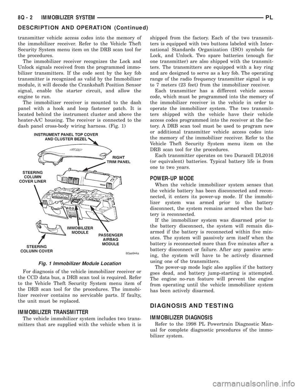
The immobilizer receiver is mounted to the dash
panel with a hook and loop fastener patch. It is
located behind the instrument cluster and above the
heater-A/C housing. The receiver is connected to the
dash panel cross-body wiring harness. (Fig. 1)
For diagnosis of the vehicle immobilizer receiver or
the CCD data bus, a DRB scan tool is required. Refer
to the Vehicle Theft Security System menu item of
the DRB scan tool for the procedures. The immobi-
lizer receiver contains no servicable parts. If faulty,
the unit must be replaced.
IMMOBILIZER TRANSMITTER
The vehicle immobilizer system includes two trans-
mitters that are supplied with the vehicle when it isshipped from the factory. Each of the two transmit-
ters is equipped with two buttons labeled with Inter-
national Standards Organization (ISO) symbols for
Lock, and Unlock. Two spare batteries (enough for
one transmitter) are also shipped with the transmit-
ters. The transmitters are equipped with a key ring
and are designed to serve as a key fob. The operating
range of the radio frequency transmitter signal is up
to 7 meters (23 feet) from the immobilizer receiver.
Each transmitter has a different vehicle access
code, which must be programmed into the memory of
the immobilizer receiver in the vehicle in order to
operate the immobilizer system. The two transmit-
ters shipped with the vehicle have their vehicle
access codes programmed into the receiver at the fac-
tory. A DRB scan tool must be used to program new
or additional transmitter vehicle access codes into
the memory of the immobilizer receiver. Refer to the
Vehicle Theft Security System menu item on the
DRB scan tool for the procedures.
Each transmitter operates on two Duracell DL2016
(or equivalent) batteries. Typical battery life is from
one to two years.
POWER-UP MODE
When the vehicle immobilizer system senses that
the vehicle battery has been disconnected and recon-
nected, it enters its power-up mode. If the immobi-
lizer system was armed prior to the battery
disconnect, the system remains armed when the bat-
tery is reconnected.
If the immobilizer system was disarmed prior to
the battery disconnect, the system will remain dis-
armed if the battery is reconnected within five min-
utes. The system will passively arm itself when the
battery is reconnected more than five minutes after a
battery disconnect or failure. After any passive arm-
ing, the system will have to be actively disarmed
using one of the transmitters.
The power-up mode logic also applies if the battery
goes dead, and battery jump-starting is attempted.
The engine no-run feature will prevent the engine
from operating until the vehicle immobilizer system
has been actively disarmed.
DIAGNOSIS AND TESTING
IMMOBILIZER DIAGNOSIS
Refer to the 1998 PL Powertrain Diagnostic Man-
ual for complete diagnostic procedures of the immo-
bilizer system.
Fig. 1 Immobilizer Module Location
8Q - 2 IMMOBILIZER SYSTEMPL
DESCRIPTION AND OPERATION (Continued)
Page 378 of 1200
SERVICE PROCEDURES
VEHICLE IMMOBILIZER SYSTEM
WARNING: ON VEHICLES EQUIPPED WITH AIR-
BAGS, REFER TO GROUP 8M - PASSIVE
RESTRAINT SYSTEMS BEFORE ATTEMPTING ANY
STEERING WHEEL, STEERING COLUMN, OR
INSTRUMENT PANEL COMPONENT DIAGNOSIS OR
SERVICE. FAILURE TO TAKE THE PROPER PRE-
CAUTIONS COULD RESULT IN ACCIDENTAL AIR-
BAG DEPLOYMENT AND POSSIBLE PERSONAL
INJURY.
NOTE: The following tests may not prove conclu-
sive in the diagnosis of this system. The most reli-
able, efficient, and accurate means to diagnose the
Vehicle Immobilizer System involves the use of a
DRB scan tool. Refer to the Vehicle Theft Security
System menu item on the DRB scan tool for the
procedures.
The vehicle immobilizer system and the Chrysler
Collision Detection (CCD) data bus network should
be diagnosed using the DRB scan tool. The DRB will
allow confirmation that the CCD data bus is func-
tional, that the immobilizer receiver is placing the
proper messages on the CCD data bus, and that the
Powertrain Control Module (PCM) is receiving the
CCD data bus messages. Refer to the Vehicle Theft
Security System menu item on the DRB scan tool for
the procedures. Refer to 8W-39 - Vehicle Theft Secu-
rity System in Group 8W - Wiring Diagrams for com-
plete circuit descriptions and diagrams.
(1) With the ignition switch in the Off position,
depress the Lock or Unlock button of the immobilizer
transmitter. Listen for the immobilizer receiver to
issue an audible chirp (Unlock) or chirps (Lock). If
OK, go to Step 2. If not OK, replace the transmitter
batteries with known good units and repeat Step 1. If
still not OK, go to Step 2.
(2) Check the fuse in the Power Distribution Cen-
ter (PDC). If OK, go to Step 3. If not OK, repair the
shorted circuit or component as required and replace
the faulty fuse.
(3) Disconnect and isolate the battery negative
cable. Unplug the wire harness connector at the
immobilizer receiver. Check for continuity between
the ground circuit cavity of the immobilizer receiver
wire harness connector and a good ground. There
should be continuity. If OK, go to Step 4. If not OK,
repair the open circuit to ground as required.
(4) Connect the battery negative cable. Check for
battery voltage at the fused B(+) circuit cavity of the
immobilizer receiver wire harness connector. If OK,
refer to the Vehicle Theft Security System menu itemon the DRB scan tool for further diagnosis. If not
OK, repair the open circuit to the PDC fuse as
required.REMOVAL AND INSTALLATION
IMMOBILIZER RECEIVER
WARNING: ON VEHICLES EQUIPPED WITH AIR-
BAGS, REFER TO GROUP 8M - PASSIVE
RESTRAINT SYSTEMS BEFORE ATTEMPTING ANY
STEERING WHEEL, STEERING COLUMN, OR
INSTRUMENT PANEL COMPONENT DIAGNOSIS OR
SERVICE. FAILURE TO TAKE THE PROPER PRE-
CAUTIONS COULD RESULT IN ACCIDENTAL AIR-
BAG DEPLOYMENT AND POSSIBLE PERSONAL
INJURY.
(1) Disconnect and isolate the battery negative
cable.
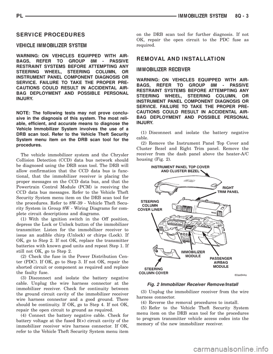
(2) Remove the Instrument Panel Top Cover and
Cluster Bezel and Right Trim panel. Remove the
receiver from the dash panel above the heater-A/C
housing (Fig. 2).
(3) Unplug the immobilizer receiver from the wire
harness connector.
(4) Reverse the removal procedures to install.
(5) Refer to the Vehicle Theft Security System
menu item on the DRB scan tool for the procedures
to program transmitter vehicle access codes into the
memory of the new immobilizer receiver.
Fig. 2 Immobilizer Receiver Remove/Install
PLIMMOBILIZER SYSTEM 8Q - 3
Page 410 of 1200
8W-02 COMPONENT INDEX
Component Page
A/C Compressor Clutch..................8W-42
A/C Compressor Clutch Relay.............8W-42
A/C Cycling Switch.....................8W-42
A/C Heater Blower Motor................8W-42
A/C Heater Control.....................8W-42
A/C Pressure Switches...................8W-42
ABS Warning Lamp Relay................8W-35
Airbag Control Module...................8W-43
Airbags..............................8W-43
Antenna..............................8W-47
Ash Receiver Lamp.....................8W-44
Automatic Shut Down Relay..............8W-30
Back-Up Lamp Switch...................8W-51
Back-Up Lamps........................8W-51
Battery..............................8W-20
Battery Temperature Sensor..............8W-30
Blower Motor Resistor Block..............8W-42
Brake Warning Lamp Switch...........8W-40, 50
Camshaft Position Sensor................8W-30
Center High Mounted Stop Lamp..........8W-51
Cigar Lighter Relay.....................8W-41
Cigar Lighter/Power Outlet...............8W-41
Circuit Breakers.......................8W-11
Clockspring.....................8W-30, 41, 61
Clutch Pedal Position Switch...........8W-10, 21
Combination Flasher....................8W-52
Controller Anti-Lock Brake...............8W-35
Crankshaft Position Sensor...............8W-30
Data Link Connector....................8W-30
Daytime Running Lamp Module...........8W-50
Diode No. 1........................8W-15, 42
Diode No. 2......................8W-10, 11, 44
Diode No. 3......................8W-11,44,70
Dome Lamp...........................8W-44
Door Ajar Switches.....................8W-44
Door Jamb Switches....................8W-44
Door Lock Motors......................8W-61
Door Lock Motors......................8W-61
Door Lock Switches.....................8W-61
Duty Cycle Evap/Purge Solenoid...........8W-30
EGR Transducer Solenoid................8W-30
Engine Coolant Temperature Sensor........8W-30
Engine Oil Pressure Switch...............8W-40
Engine Starter Motor....................8W-21
Engine Starter Motor Relay...............8W-21
Fog Lamp Relays....................8W-50, 51
Fog Lamp Switches..................8W-50, 51
Fog Lamps.........................8W-50, 51
Fuel Injectors..........................8W-30
Fuel Pump Module.....................8W-30
Fuel Pump Relay.......................8W-30
Fuse Block............................8W-11Component Page
Fuses (FB)............................8W-11
Fuses (PDC)...........................8W-10
Fusible Link........................8W-20, 21
Generator.............................8W-20
Glove Box Lamp And Switch..............8W-44
Grounds..............................8W-15
Halo Lamp............................8W-44
Headlamp Dimmer And Optical Horn Switch .8W-50
Headlamp Leveling Motors...............8W-50
Headlamp Leveling Switch...............8W-50
Headlamp Switch.......................8W-50
Headlamps............................8W-50
High Speed Warning Module..............8W-40
Horn Relay...........................8W-41
Horn Switches.........................8W-41
Horns................................8W-41
IAT/Map Sensor........................8W-30
Idle Air Control Motor...................8W-30
Ignition Coil Pack......................8W-30
Ignition Switch........................8W-10
Illumination Lamps.....................8W-40
Immobilizer...........................8W-61
Immobilizer Engine Sensor............8W-30, 61
Indicator Lamps........................8W-40
Instrument Cluster.....................8W-40
Intermittent Wipe/Wash Switch............8W-53
Key-In Switch.........................8W-40
Knock Sensor..........................8W-30
License Lamps.........................8W-51
Map/Reading Lamps....................8W-44
Noise Supressor.....................8W-10, 30
Oxygen Sensors........................8W-30
Park Brake Switch...................8W-40, 50
Park/Neutral Position Switch...........8W-30, 51
Park/Turn Signal Lamps..............8W-50, 52
Power Distribution Center................8W-10
Power Folding Mirror Relay...............8W-62
Power Mirror Fuse Holder................8W-62
Power Mirrors.........................8W-62
Power Steering Pressure Switch...........8W-30
Power Sunroof Motor....................8W-64
Power Window Motors...................8W-60
Power Window Switches.................8W-60
Powertrain Control Module...............8W-30
PRNDL Lamp.........................8W-44
Radiator Fan Motor.....................8W-42
Radio................................8W-47
Rear Window Defogger..................8W-48
Rear Window Defogger Switch.............8W-48
Remote Keyless Entry Module.............8W-61
Remote Keyless Entry Program
Module Connector....................8W-61
PL8W - 02 COMPONENT INDEX 8W - 02 - 1
Page 412 of 1200
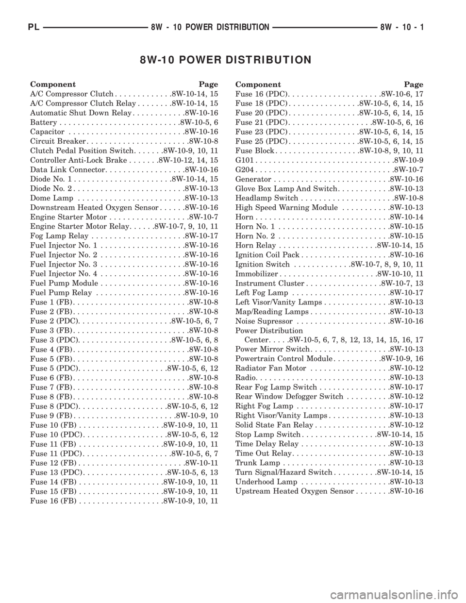
8W-10 POWER DISTRIBUTION
Component Page
A/C Compressor Clutch.............8W-10-14, 15
A/C Compressor Clutch Relay........8W-10-14, 15
Automatic Shut Down Relay............8W-10-16
Battery...........................8W-10-5, 6
Capacitor..........................8W-10-16
Circuit Breaker.......................8W-10-8
Clutch Pedal Position Switch.......8W-10-9, 10, 11
Controller Anti-Lock Brake.......8W-10-12, 14, 15
Data Link Connector..................8W-10-16
Diode No. 1......................8W-10-14, 15
Diode No. 2.........................8W-10-13
Dome Lamp........................8W-10-13
Downstream Heated Oxygen Sensor......8W-10-16
Engine Starter Motor..................8W-10-7
Engine Starter Motor Relay......8W-10-7, 9, 10, 11
Fog Lamp Relay.....................8W-10-17
Fuel Injector No. 1...................8W-10-16
Fuel Injector No. 2...................8W-10-16
Fuel Injector No. 3...................8W-10-16
Fuel Injector No. 4...................8W-10-16
Fuel Pump Module...................8W-10-16
Fuel Pump Relay....................8W-10-16
Fuse 1 (FB)..........................8W-10-8
Fuse 2 (FB)..........................8W-10-8
Fuse 2 (PDC).....................8W-10-5, 6, 7
Fuse 3 (FB)..........................8W-10-8
Fuse 3 (PDC).....................8W-10-5, 6, 8
Fuse 4 (FB)..........................8W-10-8
Fuse 5 (FB)..........................8W-10-8
Fuse 5 (PDC)....................8W-10-5, 6, 12
Fuse 6 (FB)..........................8W-10-8
Fuse 7 (FB)..........................8W-10-8
Fuse 8 (FB)..........................8W-10-8
Fuse 8 (PDC)....................8W-10-5, 6, 12
Fuse 9 (FB).......................8W-10-9, 10
Fuse 10 (FB)...................8W-10-9, 10, 11
Fuse 10 (PDC)...................8W-10-5, 6, 12
Fuse 11 (FB)...................8W-10-9, 10, 11
Fuse 11 (PDC)....................8W-10-5, 6, 7
Fuse 12 (FB)........................8W-10-11
Fuse 13 (PDC)...................8W-10-5, 6, 13
Fuse 14 (FB)...................8W-10-9, 10, 11
Fuse 15 (FB)...................8W-10-9, 10, 11
Fuse 16 (FB)...................8W-10-9, 10, 11Component Page
Fuse 16 (PDC).....................8W-10-6, 17
Fuse 18 (PDC)................8W-10-5, 6, 14, 15
Fuse 20 (PDC)................8W-10-5, 6, 14, 15
Fuse 21 (PDC)...................8W-10-5, 6, 16
Fuse 23 (PDC)................8W-10-5, 6, 14, 15
Fuse 25 (PDC)................8W-10-5, 6, 14, 15
Fuse Block...................8W-10-8, 9, 10, 11
G101...............................8W-10-9
G204...............................8W-10-7
Generator..........................8W-10-16
Glove Box Lamp And Switch............8W-10-13
Headlamp Switch.....................8W-10-8
High Speed Warning Module...........8W-10-13
Horn..............................8W-10-14
Horn No. 1.........................8W-10-15
Horn No. 2.........................8W-10-15
Horn Relay......................8W-10-14, 15
Ignition Coil Pack....................8W-10-16
Ignition Switch.............8W-10-7, 8, 9, 10, 11
Immobilizer......................8W-10-10, 11
Instrument Cluster.................8W-10-7, 13
Left Fog Lamp......................8W-10-17
Left Visor/Vanity Lamps...............8W-10-13
Map/Reading Lamps..................8W-10-13
Noise Supressor.....................8W-10-16
Power Distribution
Center.....8W-10-5, 6, 7, 8, 12, 13, 14, 15, 16, 17
Power Mirror Switch..................8W-10-13
Powertrain Control Module...........8W-10-9, 16
Radiator Fan Motor..................8W-10-12
Radio..............................8W-10-13
Rear Fog Lamp Switch................8W-10-17
Rear Window Defogger Switch..........8W-10-12
Right Fog Lamp.....................8W-10-17
Right Visor/Vanity Lamps..............8W-10-13
Solid State Fan Relay.................8W-10-12
Stop Lamp Switch.................8W-10-14, 15
Time Delay Relay....................8W-10-13
Time Out Relay......................8W-10-13
Trunk Lamp........................8W-10-13
Turn Signal/Hazard Switch..........8W-10-14, 15
Underhood Lamp....................8W-10-13
Upstream Heated Oxygen Sensor........8W-10-16
PL8W - 10 POWER DISTRIBUTION 8W - 10 - 1
Page 421 of 1200

ENGINE
STARTER
MOTOR
RELAY
(IN PDC)
A41
14
YL
C2428
YL14 A41
2810FUSE
15A
30
BLOCK FUSE
9
BATT A1
SWITCH
IGNITION
A21
14
DB
ATX MTX
A41
14
YL
1
2
SWITCH POSITION
PEDAL
CLUTCH
T141
14
YL/RD
A41
14
YL
3
0 2 11
203
10
1
203
8
BK/WT14 A31
315A
FUSE
11
2910A
FUSE
9
14
14FUSE20A
3416FUSE10A
36
3520A
FUSE
15
FUSE
BLOCK
3C242
1C101
1516
91011
3 ACC 1 START
2 RUN
0 OFF
142
IMMOBILIZER
A41
16
YL
A41
16
YL
(8W-21-3)(8W-11-14)(8W-11-3) (8W-10-7)
(8W-11-16) (8W-11-14)
(8W-11-20) (8W-11-20)(8W-11-20)(8W-11-3) (8W-10-7)
(8W-61-8)
8W - 10 - 10 8W-10 POWER DISTRIBUTION
LHD BUILT-UP-EXPORTPL
J988W-18199
Page 422 of 1200

10FUSE15A
30
BLOCK FUSE
315A
FUSE
11
3210A
FUSE
12
14FUSE20A
3416FUSE10A
36
3520A
FUSE
15
FUSE
BLOCK
ENGINE
STARTER
MOTOR
RELAY
(IN PDC)
A41
14
YL
C2428
YL14 A41
289
BATT A1
SWITCH IGNITION
A21
14
DB
ATX MTX
A41
14
YL
1
2
SWITCH POSITION
PEDAL
CLUTCH
T141
14
YL/RD
A41
14
YL
3
0 2 11
203
10
1
203
8
BK/WT14 A31
3C242
1C101
161514
1211103 ACC 1 START
2 RUN
0 OFF
142
IMMOBILIZER
A41
16
YL
A41
16
YL
(8W-11-14)(8W-11-4)
(8W-11-16) (8W-11-14)
(8W-11-20) (8W-11-20)(8W-11-20)(8W-11-4)
(8W-21-4)(8W-10-7)
(8W-10-7)
(8W-61-8)
PL8W-10 POWER DISTRIBUTION
RHD BUILT-UP-EXPORT8W - 10 - 11
8200J988W-1
Page 430 of 1200
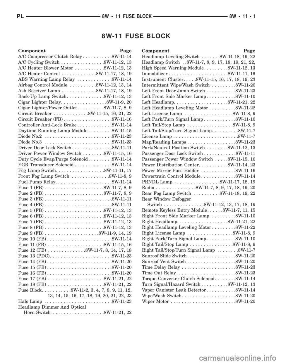
8W-11 FUSE BLOCK
Component Page
A/C Compressor Clutch Relay...........8W-11-14
A/C Cycling Switch................8W-11-12, 13
A/C Heater Blower Motor...........8W-11-12, 13
A/C Heater Control.............8W-11-17, 18, 19
ABS Warning Lamp Relay.............8W-11-14
Airbag Control Module..........8W-11-12, 13, 14
Ash Receiver Lamp.............8W-11-17, 18, 19
Back-Up Lamp Switch..............8W-11-12, 13
Cigar Lighter Relay.................8W-11-9, 20
Cigar Lighter/Power Outlet..........8W-11-7, 8, 9
Circuit Breaker.............8W-11-15, 16, 21, 22
Circuit Breaker (FB)..................8W-11-16
Controller Anti-Lock Brake.............8W-11-14
Daytime Running Lamp Module.........8W-11-15
Diode No.2.........................8W-11-23
Diode No.3.........................8W-11-23
Driver Door Lock Switch...............8W-11-11
Driver Power Window Switch........8W-11-15, 16
Duty Cycle Evap/Purge Solenoid.........8W-11-14
EGR Transducer Solenoid..............8W-11-14
Fog Lamp Switch..................8W-11-11,17
Front Fog Lamp Switch..............8W-11-8, 9
Fuel Pump Relay.....................8W-11-14
Fuse 1 (FB)......................8W-11-7, 8, 9
Fuse 2 (FB)......................8W-11-7, 8, 9
Fuse 3 (FB).........................8W-11-11
Fuse 4 (FB).........................8W-11-11
Fuse 5 (FB)......................8W-11-12, 13
Fuse 6 (FB)......................8W-11-12, 13
Fuse 7 (FB)......................8W-11-12, 13
Fuse 8 (FB)......................8W-11-12, 13
Fuse 9 (FB)....................8W-11-9, 14, 19
Fuse 10 (FB)........................8W-11-14
Fuse 11 (FB).....................8W-11-15, 16
Fuse 12 (FB)..............8W-11-7, 8, 14, 17, 18
Fuse 13 (PDC).......................8W-11-23
Fuse 14 (FB)........................8W-11-20
Fuse 15 (FB)........................8W-11-20
Fuse 16 (FB)........................8W-11-20
Fuse 17 (FB).....................8W-11-21, 22
Fuse 18 (FB).....................8W-11-21, 22
Fuse Block...........8W-11-2, 3, 4, 7, 8, 9, 11, 12,
13, 14, 15, 16, 17, 18, 19, 20, 21, 22, 23
Halo Lamp.........................8W-11-23
Headlamp Dimmer And Optical
Horn Switch...................8W-11-21, 22Component Page
Headlamp Leveling Switch.......8W-11-18, 19, 22
Headlamp Switch . .8W-11-7, 8, 9, 17, 18, 19, 21, 22,
High Speed Warning Module.........8W-11-12, 13
Immobilizer......................8W-11-11,16
Instrument Cluster.....8W-11-15, 16, 17, 18, 19, 23
Intermittent Wipe/Wash Switch.........8W-11-20
Left Front Door Jamb Switch...........8W-11-23
Left Front Side Marker Lamp...........8W-11-10
Left Headlamp....................8W-11-21, 22
Left Headlamp Leveling Motor..........8W-11-22
Left License Lamp..................8W-11-8, 9
Left Park/Turn Signal Lamp............8W-11-10
Left Tail/Stop Lamp.................8W-11-8, 9
Left Tail/Stop/Turn Signal Lamp..........8W-11-7
License Lamp........................8W-11-7
Map/Reading Lamps..................8W-11-23
Park/Neutral Position Switch........8W-11-12, 13
Passenger Door Lock Switch............8W-11-11
Passenger Power Window Switch.....8W-11-15, 16
Power Distribution Center...........8W-11-14, 23
Power Mirror Fuse Holder.............8W-11-16
Powertrain Control Module.............8W-11-14
PRNDL Lamp.................8W-11-17, 18, 19
Radio...............8W-11-7, 8, 9, 17, 18, 19, 20
Rear Fog Lamp Switch..........8W-11-18, 19, 22
Rear Window Defogger
Switch...............8W-11-12, 13, 17, 18, 19
Remote Keyless Entry Module......8W-11-7, 11, 15
Right Front Side Marker Lamp..........8W-11-10
Right Headlamp..................8W-11-21, 22
Right Headlamp Leveling Motor.........8W-11-22
Right License Lamp.................8W-11-8, 9
Right Park/Turn Signal Lamp...........8W-11-10
Right Tail/Stop Lamp................8W-11-8, 9
Right Tail/Stop/Turn Signal Lamp........8W-11-7
Sunroof Slide Switch..................8W-11-20
Sunroof Vent Switch..................8W-11-20
Time Delay Relay....................8W-11-23
Time Out Relay......................8W-11-23
Torque Converter Clutch Solenoid........8W-11-14
Turn Signal/Hazard Switch..........8W-11-12, 13
Vapor Canister Leak Detector...........8W-11-14
Wipe/Wash Switch....................8W-11-20
Wiper Motor........................8W-11-20
PL8W - 11 FUSE BLOCK 8W - 11 - 1
Page 440 of 1200

FUSE
BLOCK
BATT A3
S214
24RD/YL16 F35
3SWITCH LOCK
DOOR
DRIVER PASSENGER
DOOR
LOCK
SWITCH
3
F35
16
RD/YL
F35
18
RD/YL
RD/YL18 F35 RD/YL16 F35
RD/YL16 F3524
23
10A
FUSE
4
20AFUSE
3
34
LHD RHD
1C231 C20511C231 C2051
RHD LHD
F35
16
RD/YL
REMOTE
KEYLESS
ENTRY
MODULE
2C1
RD/YL16 F35
F61
20
WT/OR
2
(EXCEPT BUILT-UP-EXPORT) SWITCH
LAMP
FOG
BUILT-UP-EXPORTEXCEPT
BUILT-UP-EXPORT
IMMOBILIZER
10C242
F35
16
RD/YL
(8W-10-8)
(8W-61-2)
(8W-61-10)
(8W-61-11) (8W-61-4)
(8W-61-10)
(8W-61-11)(8W-11-2)
(8W-11-3)
(8W-11-4)
(8W-61-6) (8W-50-12)
(8W-61-8)
PL8W-11 FUSE/FUSE BLOCK 8W - 11 - 11
8217J988W-1
Page 445 of 1200

11FUSE5A
31
BLOCK
FUSE
G5
20
DB/WT
ST-RUN A21
5
CLUSTER INSTRUMENT
11
C1
30A
(FB)
BREAKER
CIRCUIT4241
RUN A22
F21
14
TN
F21
14
TNG5
20
DB/WT
4
SWITCH WINDOW
POWER
DRIVER
C2057
TN14 F21 TN14 F21
3
SWITCH WINDOW
POWER
PASSENGER
POWER
MIRROR
FUSE
HOLDER
F21
14
TN
CIRCUIT
BREAKER
15A
S318
F21
14
TN
2
1
WINDOWSPOWER
OTHERS
7C231
LHD RHD
C23177C205
16
IMMOBILIZER
6C242
G5
20
DB/WT
(8W-40-6) (8W-10-10) (8W-10-8)
(8W-60-3)
(8W-60-4) (8W-60-3)
(8W-60-4)
(8W-62-5)
(8W-62-5)(8W-11-3)
(8W-11-4)
(8W-61-8)
8W - 11 - 16 8W-11 FUSE/FUSE BLOCK
BUILT-UP-EXPORTPL
J988W-18222