horn DODGE NEON 2000 Service Repair Manual
[x] Cancel search | Manufacturer: DODGE, Model Year: 2000, Model line: NEON, Model: DODGE NEON 2000Pages: 1285, PDF Size: 29.42 MB
Page 1 of 1285
GROUP TAB LOCATORINIntroductionINaIntroduction0Lubrication and Maintenance2Suspension3Differential and Driveline5Brakes6Clutch7Cooling8ABattery8BStarting8CCharging System8DIgnition System8EInstrument Panel and Systems8EaInstrument Panel and Systems8FAudio System8GHorns8HVehicle Speed Control System8JTurn Signal and Flashers8KWindshield Wipers and Washers8LLamps8LaLamps8MRestraint System8NElectrically Heated Systems8OPower Distribution Systems8PPower Door Locks8QImmobilizer System8SPower Windows8TPower Mirrors8TaPower Mirrors8UChime Warning/Reminder System8WWiring Diagrams - LHD and RHD9Engine11Exhaust System13Frame and Bumpers14Fuel System19Steering21Transaxle22Tires and Wheels23Body24Heating and Air Conditioning24aHeating and Air Conditioning25Emission Control Systems
Page 280 of 1285
HORNS
TABLE OF CONTENTS
page page
DESCRIPTION AND OPERATION
INTRODUCTION..........................1
DIAGNOSIS AND TESTING
HORN..................................2
HORN RELAY............................2
HORN SWITCH...........................2HORN SYSTEM TEST......................2
REMOVAL AND INSTALLATION
HORN..................................4
HORN RELAY............................4
HORN SWITCH...........................5
DESCRIPTION AND OPERATION
INTRODUCTION
WARNING: ON VEHICLES EQUIPPED WITH AIR-
BAG, SEE GROUP 8M, PASSIVE RESTRAINT SYS-
TEMS FOR STEERING WHEEL REMOVAL.
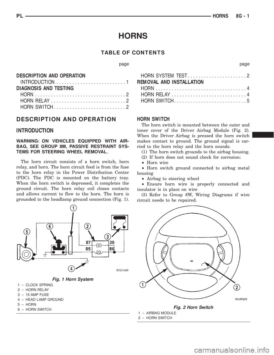
The horn circuit consists of a horn switch, horn
relay, and horn. The horn circuit feed is from the fuse
to the horn relay in the Power Distribution Center
(PDC). The PDC is mounted on the battery tray.
When the horn switch is depressed, it completes the
ground circuit. The horn relay coil closes contacts
and allows current to flow to the horn. The horn is
grounded to the headlamp ground connection (Fig. 1).
HORN SWITCH
The horn switch is mounted between the outer and
inner cover of the Driver Airbag Module (Fig. 2).
When the Driver Airbag is pressed the horn switch
makes contact to ground. The ground signal is car-
ried to the horn relay and the horn sounds.
(1) The horn switch grounds to the airbag housing.
(2) If horn does not sound check for corrosion:
²Horn wire
²Horn switch ground connected to airbag metal
housing
²Airbag to steering wheel
²Ensure horn wire is properly connected and
insulator is in place on wire
(3) Refer to Group 8W, Wiring Diagrams if wire
circuit needs to be repaired.
Fig. 1 Horn System
1 ± CLOCK SPRING
2 ± HORN RELAY
3 ± 15 AMP FUSE
4 ± HEAD LAMP GROUND
5 ± HORN
6 ± HORN SWITCH
Fig. 2 Horn Switch
1 ± AIRBAG MODULE
2 ± HORN SWITCH
PLHORNS 8G - 1
Page 281 of 1285
DIAGNOSIS AND TESTING
HORN
(1) Disconnect wire connector at horn.
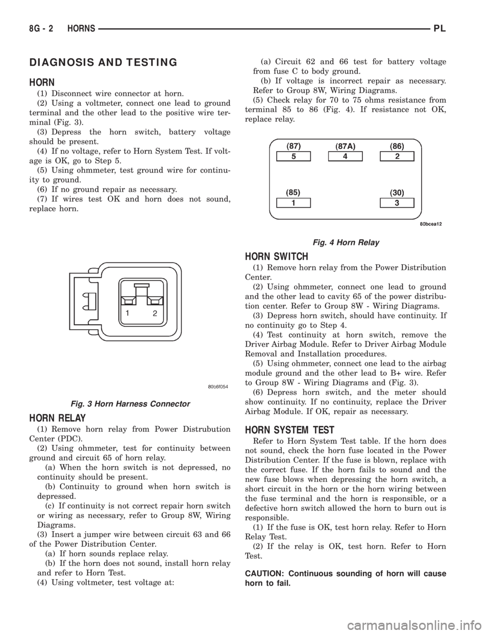
(2) Using a voltmeter, connect one lead to ground
terminal and the other lead to the positive wire ter-
minal (Fig. 3).
(3) Depress the horn switch, battery voltage
should be present.
(4) If no voltage, refer to Horn System Test. If volt-
age is OK, go to Step 5.
(5) Using ohmmeter, test ground wire for continu-
ity to ground.
(6) If no ground repair as necessary.
(7) If wires test OK and horn does not sound,
replace horn.
HORN RELAY
(1) Remove horn relay from Power Distrubution
Center (PDC).
(2) Using ohmmeter, test for continuity between
ground and circuit 65 of horn relay.
(a) When the horn switch is not depressed, no
continuity should be present.
(b) Continuity to ground when horn switch is
depressed.
(c) If continuity is not correct repair horn switch
or wiring as necessary, refer to Group 8W, Wiring
Diagrams.
(3) Insert a jumper wire between circuit 63 and 66
of the Power Distribution Center.
(a) If horn sounds replace relay.
(b) If the horn does not sound, install horn relay
and refer to Horn Test.
(4) Using voltmeter, test voltage at:(a) Circuit 62 and 66 test for battery voltage
from fuse C to body ground.
(b) If voltage is incorrect repair as necessary.
Refer to Group 8W, Wiring Diagrams.
(5) Check relay for 70 to 75 ohms resistance from
terminal 85 to 86 (Fig. 4). If resistance not OK,
replace relay.
HORN SWITCH
(1) Remove horn relay from the Power Distribution
Center.
(2) Using ohmmeter, connect one lead to ground
and the other lead to cavity 65 of the power distribu-
tion center. Refer to Group 8W - Wiring Diagrams.
(3) Depress horn switch, should have continuity. If
no continuity go to Step 4.
(4) Test continuity at horn switch, remove the
Driver Airbag Module. Refer to Driver Airbag Module
Removal and Installation procedures.
(5) Using ohmmeter, connect one lead to the airbag
module ground and the other lead to B+ wire. Refer
to Group 8W - Wiring Diagrams and (Fig. 3).
(6) Depress horn switch, and the meter should
show continuity. If no continuity, replace the Driver
Airbag Module. If OK, repair as necessary.
HORN SYSTEM TEST
Refer to Horn System Test table. If the horn does
not sound, check the horn fuse located in the Power
Distribution Center. If the fuse is blown, replace with
the correct fuse. If the horn fails to sound and the
new fuse blows when depressing the horn switch, a
short circuit in the horn or the horn wiring between
the fuse terminal and the horn is responsible, or a
defective horn switch allowed the horn to burn out is
responsible.
(1) If the fuse is OK, test horn relay. Refer to Horn
Relay Test.
(2) If the relay is OK, test horn. Refer to Horn
Test.
CAUTION: Continuous sounding of horn will cause
horn to fail.
Fig. 3 Horn Harness Connector
Fig. 4 Horn Relay
8G - 2 HORNSPL
Page 282 of 1285
Should the horn sound continuously:
²Unplug the horn relay from Power Distribution
Center.²Refer to Horn Relay Test.
Refer to Group 8W, wiring Diagrams for circuit and
wiring information.
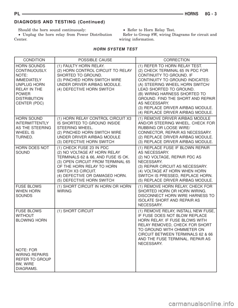
HORN SYSTEM TEST
CONDITION POSSIBLE CAUSE CORRECTION
HORN SOUNDS
CONTINUOUSLY.
NOTE:
IMMEDIATELY
UNPLUG HORN
RELAY IN THE
POWER
DISTRIBUTION
CENTER (PDC)(1) FAULTY HORN RELAY.
(2) HORN CONTROL CIRCUIT TO RELAY
SHORTED TO GROUND.
(3) PINCHED HORN SWITCH WIRE
UNDER DRIVER AIRBAG MODULE.
(4) DEFECTIVE HORN SWITCH(1) REFER TO HORN RELAY TEST.
(2) CHECK TERMINAL 65 IN PDC FOR
CONTINUITY TO GROUND. IF
CONTINUITY TO GROUND INDICATES:
(A) STEERING WHEEL HORN SWITCH/
LEAD SHORTED TO GROUND.
(B) WIRING HARNESS SHORTED TO
GROUND. FIND THE SHORT AND REPAIR
AS NECESSARY.
(3) REPLACE DRIVER AIRBAG MODULE.
(4) REPLACE DRIVER AIRBAG MODULE.
HORN SOUND
INTERMITTENTLY
AS THE STEERING
WHEEL IS
TURNED.(1) HORN RELAY CONTROL CIRCUIT X3
IS SHORTED TO GROUND INSIDE
STEERING WHEEL.
(2) PINCHED HORN SWITCH WIRE
UNDER DRIVER AIRBAG MODULE
(3) DEFECTIVE HORN SWITCH(1) REMOVE DRIVER AIRBAG MODULE
AND/OR STEERING WHEEL. CHECK FOR
RUBBING OR LOOSE WIRE/
CONNECTOR, REPAIR AS NECESSARY.
(2) REPLACE DRIVER AIRBAG MODULE.
(3) REPLACE DRIVER AIRBAG MODULE.
HORN DOES NOT
SOUND(1) CHECK FUSE 23 IN PDC
(2) NO VOLTAGE AT HORN RELAY
TERMINALS 62 & 66, AND FUSE IS OK.
(3) OPEN CIRCUIT FROM TERMINAL 65
OF THE HORN RELAY TO HORN
SWITCH X3 CIRCUIT.
(4) DEFECTIVE OR DAMAGED HORN.
(5) DEFECTIVE HORN SWITCH(1) REPLACE FUSE IF BLOWN REPAIR
AS NECESSARY.
(2) NO VOLTAGE, REPAIR PDC AS
NECESSARY.
(3) REPAIR CIRCUIT AS NECESSARY.
(4) VOLTAGE AT HORN WHEN HORN
SWITCH IS PRESSED, REPLACE HORN.
(5) REPLACE DRIVER AIRBAG MODULE.
FUSE BLOWS
WHEN HORN
SOUNDS(1) SHORT CIRCUIT IN HORN OR HORN
WIRING(1) REMOVE HORN RELAY, CHECK FOR
SHORTED HORN OR HORN WIRING.
DISCONNECT HORN WIRE HARNESS TO
ISOLATE SHORT AND REPAIR AS
NECESSARY.
FUSE BLOWS
WITHOUT
BLOWING HORN(1) SHORT CIRCUIT (1) REMOVE RELAY, INSTALL NEW FUSE,
IF FUSE DOES NOT BLOW REPLACE
HORN RELAY. IF FUSE BLOWS WITH
RELAY REMOVED, CHECK FOR SHORT
TO GROUND WITH OHMMETER ON
CIRCUIT BETWEEN TERMINALS 62 & 66
AND THE FUSE TERMINAL. REPAIR AS
NECESSARY.
NOTE: FOR
WIRING REPAIRS
REFER TO GROUP
8W, WIRE
DIAGRAMS.
PLHORNS 8G - 3
DIAGNOSIS AND TESTING (Continued)
Page 283 of 1285
REMOVAL AND INSTALLATION
HORN
REMOVAL
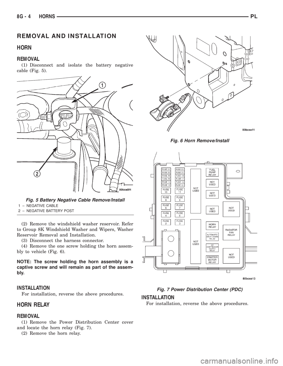
(1) Disconnect and isolate the battery negative
cable (Fig. 5).
(2) Remove the windshield washer reservoir. Refer
to Group 8K Windshield Washer and Wipers, Washer
Reservoir Removal and Installation.
(3) Disconnect the harness connector.
(4) Remove the one screw holding the horn assem-
bly to vehicle (Fig. 6).
NOTE: The screw holding the horn assembly is a
captive screw and will remain as part of the assem-
bly.
INSTALLATION
For installation, reverse the above procedures.
HORN RELAY
REMOVAL
(1) Remove the Power Distribution Center cover
and locate the horn relay (Fig. 7).
(2) Remove the horn relay.
INSTALLATION
For installation, reverse the above procedures.
Fig. 5 Battery Negative Cable Remove/Install
1 ± NEGATIVE CABLE
2 ± NEGATIVE BATTERY POST
Fig. 6 Horn Remove/Install
Fig. 7 Power Distribution Center (PDC)
8G - 4 HORNSPL
Page 284 of 1285
HORN SWITCH
REMOVAL
(1) Disconnect and isolate the battery negative
cable (Fig. 5).
(2) Remove the Driver Airbag Module. Refer to
Group 8M Passive Restraint Systems, Driver Airbag
Module Removal and Installation.
(3) Clip off strap tie holding the horn switch wire
to the airbag module.
(4) Unclip horn switch wire connector from airbag
module.(5) Remove four torx screws from top side of air-
bag module.
(6) Fold airbag module cover down to expose the
horn switch.
(7) Lift the horn switch off indexing tabs and
remove from vehicle.
INSTALLATION
For installation, reverse the above procedures.
PLHORNS 8G - 5
REMOVAL AND INSTALLATION (Continued)
Page 292 of 1285
TURN SIGNAL and HAZARD WARNING SYSTEMS
TABLE OF CONTENTS
page page
GENERAL INFORMATION
INTRODUCTION..........................1
DESCRIPTION AND OPERATION
HAZARD WARNING SYSTEM................2
HEADLAMP SWITCH......................2
COMBINATION FLASHER...................2DIAGNOSIS AND TESTING
MULTI-FUNCTION SWITCH.................3
REMOVAL AND INSTALLATION
COMBINATION FLASHER...................5
MULTI-FUNCTION SWITCH.................5
GENERAL INFORMATION
INTRODUCTION
WARNING: ON VEHICLES EQUIPPED WITH AIR-
BAG, SEE GROUP 8M, PASSIVE RESTRAINT SYS-
TEMS FOR AIRBAG REMOVAL.
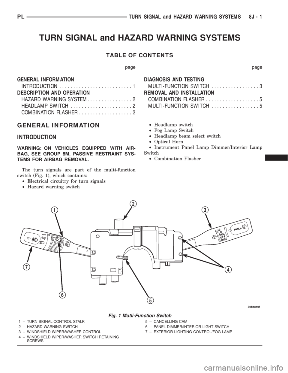
The turn signals are part of the multi-function
switch (Fig. 1), which contains:
²Electrical circuitry for turn signals
²Hazard warning switch²Headlamp switch
²Fog Lamp Switch
²Headlamp beam select switch
²Optical Horn
²Instrument Panel Lamp Dimmer/Interior Lamp
Switch
²Combination Flasher
Fig. 1 Mutli-Function Switch
1 ± TURN SIGNAL CONTROL STALK
2 ± HAZARD WARNING SWITCH
3 ± WINDSHIELD WIPER/WASHER CONTROL
4 ± WINDSHIELD WIPER/WASHER SWITCH RETAINING
SCREWS5 ± CANCELLING CAM
6 ± PANEL DIMMER/INTERIOR LIGHT SWITCH
7 ± EXTERIOR LIGHTING CONTROL/FOG LAMP
PLTURN SIGNAL and HAZARD WARNING SYSTEMS 8J - 1
Page 295 of 1285
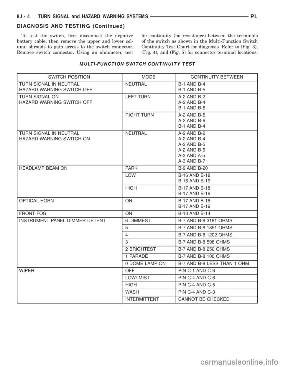
To test the switch, first disconnect the negative
battery cable, then remove the upper and lower col-
umn shrouds to gain access to the switch connector.
Remove switch connector. Using an ohmmeter, testfor continuity (no resistance) between the terminals
of the switch as shown in the Multi-Function Switch
Continuity Test Chart for diagnosis. Refer to (Fig. 3),
(Fig. 4), and (Fig. 5) for connector terminal locations.
MULTI-FUNCTION SWITCH CONTINUITY TEST
SWITCH POSITION MODE CONTINUITY BETWEEN
TURN SIGNAL IN NEUTRAL
HAZARD WARNING SWITCH OFFNEUTRAL B-1 AND B-4
B-1 AND B-5
TURN SIGNAL ON
HAZARD WARNING SWITCH OFFLEFT TURN A-2 AND B-2
A-2 AND B-4
B-1 AND B-5
RIGHT TURN A-2 AND B-5
A-2 AND B-6
B-1 AND B-4
TURN SIGNAL IN NEUTRAL
HAZARD WARNING SWITCH ONNEUTRAL A-2 AND B-2
A-2 AND B-4
A-2 AND B-5
A-2 AND B-6
A-3 AND A-5
A-3 AND B-7
HEADLAMP BEAM ON PARK B-9 AND B-20
LOW B-16 AND B-18
B-16 AND B-19
HIGH B-17 AND B-18
B-17 AND B-19
OPTICAL HORN ON B-17 AND B-18
B-17 AND B-19
FRONT FOG ON B-13 AND B-14
INSTRUMENT PANEL DIMMER DETENT 6 DIMMEST B-7 AND B-8 3181 OHMS
5 B-7 AND B-8 1851 OHMS
4 B-7 AND B-8 1202 OHMS
3 B-7 AND B-8 598 OHMS
2 BRIGHTEST B-7 AND B-8 250 OHMS
1 PARADE B-7 AND B-8 100 OHMS
0 DOME LAMP ON B-7 AND B-8 LESS THAN 1 OHM
WIPER OFF PIN C-1 AND C-6
LOW/ MIST PIN C-4 AND C-6
HIGH PIN C-4 AND C-5
WASH PIN C-4 AND C-3
INTERMITTENT CANNOT BE CHECKED
8J - 4 TURN SIGNAL and HAZARD WARNING SYSTEMSPL
DIAGNOSIS AND TESTING (Continued)
Page 347 of 1285
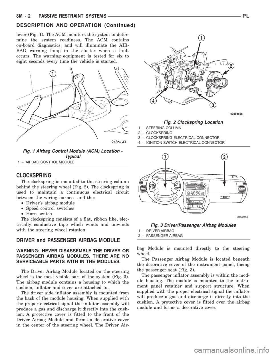
lever (Fig. 1). The ACM monitors the system to deter-
mine the system readiness. The ACM contains
on-board diagnostics, and will illuminate the AIR-
BAG warning lamp in the cluster when a fault
occurs. The warning equipment is tested for six to
eight seconds every time the vehicle is started.
CLOCKSPRING
The clockspring is mounted to the steering column
behind the steering wheel (Fig. 2). The clockspring is
used to maintain a continuous electrical circuit
between the wiring harness and the:
²Driver's airbag module
²Speed control switches
²Horn switch
The clockspring consists of a flat, ribbon like, elec-
trically conductive tape which winds and unwinds
with the steering wheel rotation.
DRIVER and PASSENGER AIRBAG MODULE
WARNING: NEVER DISASSEMBLE THE DRIVER OR
PASSENGER AIRBAG MODULES, THERE ARE NO
SERVICEABLE PARTS WITH IN THE MODULES.
The Driver Airbag Module located on the steering
wheel is the most visible part of the system (Fig. 3).
The airbag module contains a housing to which the
cushion, inflator and cover are attached to.
The driver side inflator assembly is mounted from
the back of the module housing. When supplied with
the proper electrical signal the inflator assembly will
produce a gas and discharge it directly into the cush-
ion. A protective cover is fitted to the front of the
Driver Airbag Module and forms a decorative cover
in the center of the steering wheel. The Driver Air-bag Module is mounted directly to the steering
wheel.
The Passenger Airbag Module is located beneath
the decorative cover of the instrument panel, facing
the passenger seat (Fig. 3).
The passenger inflator assembly is within the mod-
ule housing. The module is mounted to the instru-
ment panel retainer and support structure. When
supplied with the proper electrical signal the inflator
will produce a gas and discharge it directly into the
cushion. A protective cover is fitted over the airbag
module and forms a decorative cover.
Fig. 1 Airbag Control Module (ACM) Location -
Typical
1 ± AIRBAG CONTROL MODULE
Fig. 2 Clockspring Location
1 ± STEERING COLUMN
2 ± CLOCKSPRING
3 ± CLOCKSPRING ELECTRICAL CONNECTOR
4 ± IGNITION SWITCH ELECTRICAL CONNECTOR
Fig. 3 Driver/Passenger Airbag Modules
1 ± DRIVER AIRBAG
2 ± PASSENGER AIRBAG
8M - 2 PASSIVE RESTRAINT SYSTEMSPL
DESCRIPTION AND OPERATION (Continued)
Page 350 of 1285
(3) Install center console assembly. Refer to Group
23 Body, Floor Console Removal and Installation.
(4) Do not connect battery negative cable. Refer to
Diagnosis and Testing for Airbag System Test for the
proper procedures.
CLOCKSPRING
WARNING: DISCONNECT AND ISOLATE THE BAT-
TERY NEGATIVE (GROUND) CABLE BEFORE
BEGINNING ANY AIRBAG SYSTEM COMPONENT
REMOVAL OR INSTALLATION PROCEDURE. THIS
WILL DISABLE THE AIRBAG SYSTEM. FAILURE TO
DISCONNECT BATTERY COULD RESULT IN ACCI-
DENTAL AIRBAG DEPLOYMENT AND POSSIBLE
PERSONAL INJURY.
ALLOW SYSTEM CAPACITOR TO DISCHARGE
FOR 1 MINUTE BEFORE REMOVING ANY AIRBAG
COMPONENTS.
REMOVAL
(1) Place the front road wheels in the straight
ahead position then:
²Rotate the steering wheel half turn (180
degrees) to the right (clockwise).
²Lock column with ignition lock cylinder.
(2) Disconnect and isolate the battery negative
cable (Fig. 4).
(3) Wait one minute for the reserve capacitor to
discharge before removing non-deployed module.
(4) Remove steering wheel. Refer to Steering
Wheel Removal and Installation in this section.
(5) Remove upper and lower steering column
shrouds to gain access to clockspring wiring. Refer to
Group 8E Instrument Panel Systems, Steering Col-
umn Shroud Removal and Installation.
(6) Remove multi-function switch. Refer to Group
8J-Turn Signal and Hazard Warning Systems, Multi-
Function Switch Removal and Installation.
(7) Disconnect the 7-way connector between the
clockspring and the instrument panel wiring harness
at the base of the clockspring.
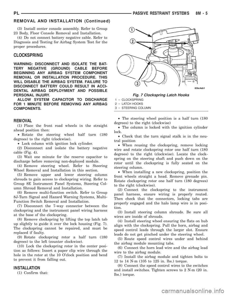
(8) Remove clockspring by lifting the top latch tab
up slightly to guide it over the lock housing (Fig. 7).
The clockspring cannot be repaired, and must be
replaced if faulty.
(9) Rotate clockspring rotor a half turn (180
degrees) to the left (counter clockwise).
(10) Lock the clockspring rotor in the center posi-
tion as follows: Insert a paper clip wire through the
hole in the rotor at the 10 O'clock position and bend
to prevent it from falling out.
INSTALLATION
(1) Confirm that:²The steering wheel position is a half turn (180
degrees) to the right (clockwise)
²The column is locked with the ignition cylinder
lock.
²Check that the turn signal stalk is in the neu-
tral position
²When reusing the clockspring, remove locking
wire and rotate clockspring rotor one half turn (180
degrees) to the right (clockwise). Locate the clock-
spring on the steering shaft and push down on the
rotor until the clockspring is fully seated on the
steering column.
²When installing a new clockspring, position the
front wheels straight a head. Remove grenade pin.
Rotate clockspring rotor one half turn (180 degrees)
to the right (clockwise).
(2) Connect the clockspring to the instrument
panel harness, ensure wiring is properly routed.
Then check that the connectors, locking tabs are
properly engaged and the halo lamp wire is in posi-
tion.
(3) Install steering column shrouds. Be sure all
wires are inside of shrouds.
(4) Install steering wheel ensuring the flats on hub
align with the clockspring. Pull the horn, airbag and
speed control leads through the larger slot. Ensure
leads do not get pinched under the steering wheel.
(5) Route speed control wires under and behind
the airbag module mounting tabs.
(6) Connect the horn lead wire and the airbag lead
wire to the airbag module.
(7) Install the airbag module and tighten bolts to
12 to 14 N´m (105 to 125 in. lbs.) torque.
(8) Connect the speed control wires to the switches
and install switches. Tighten screws to 2 N´m (20 in.
lbs.) torque.
Fig. 7 Clockspring Latch Hooks
1 ± CLOCKSPRING
2 ± LATCH HOOKS
3 ± STEERING COLUMN
PLPASSIVE RESTRAINT SYSTEMS 8M - 5
REMOVAL AND INSTALLATION (Continued)