headlamp DODGE RAM 2001 Service Owners Manual
[x] Cancel search | Manufacturer: DODGE, Model Year: 2001, Model line: RAM, Model: DODGE RAM 2001Pages: 2889, PDF Size: 68.07 MB
Page 1098 of 2889
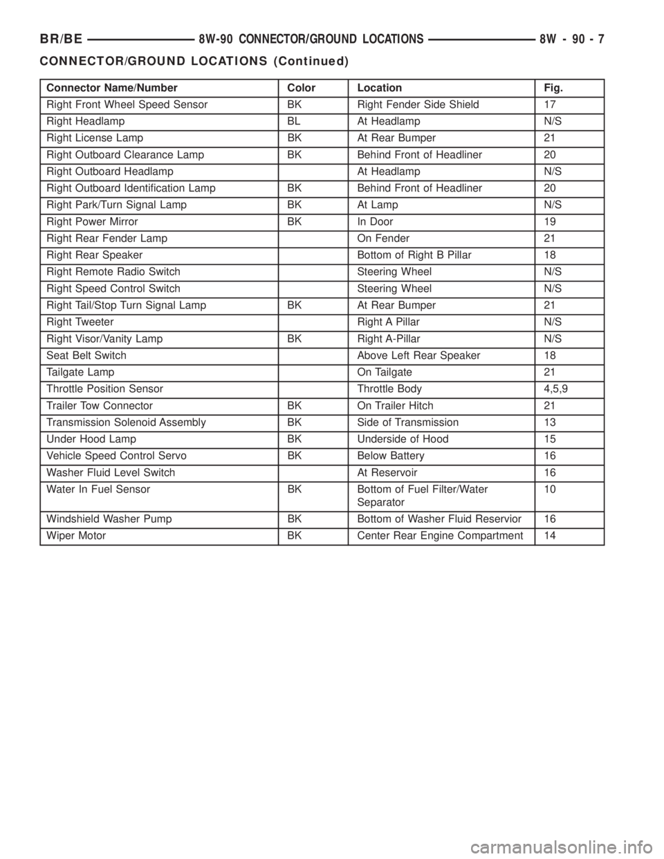
Connector Name/Number Color Location Fig.
Right Front Wheel Speed Sensor BK Right Fender Side Shield 17
Right Headlamp BL At Headlamp N/S
Right License Lamp BK At Rear Bumper 21
Right Outboard Clearance Lamp BK Behind Front of Headliner 20
Right Outboard Headlamp At Headlamp N/S
Right Outboard Identification Lamp BK Behind Front of Headliner 20
Right Park/Turn Signal Lamp BK At Lamp N/S
Right Power Mirror BK In Door 19
Right Rear Fender Lamp On Fender 21
Right Rear Speaker Bottom of Right B Pillar 18
Right Remote Radio Switch Steering Wheel N/S
Right Speed Control Switch Steering Wheel N/S
Right Tail/Stop Turn Signal Lamp BK At Rear Bumper 21
Right Tweeter Right A Pillar N/S
Right Visor/Vanity Lamp BK Right A-Pillar N/S
Seat Belt Switch Above Left Rear Speaker 18
Tailgate Lamp On Tailgate 21
Throttle Position Sensor Throttle Body 4,5,9
Trailer Tow Connector BK On Trailer Hitch 21
Transmission Solenoid Assembly BK Side of Transmission 13
Under Hood Lamp BK Underside of Hood 15
Vehicle Speed Control Servo BK Below Battery 16
Washer Fluid Level Switch At Reservoir 16
Water In Fuel Sensor BK Bottom of Fuel Filter/Water
Separator10
Windshield Washer Pump BK Bottom of Washer Fluid Reservior 16
Wiper Motor BK Center Rear Engine Compartment 14
BR/BE8W-90 CONNECTOR/GROUND LOCATIONS 8W - 90 - 7
CONNECTOR/GROUND LOCATIONS (Continued)
Page 1124 of 2889
8W-95 SPLICE LOCATIONS
TABLE OF CONTENTS
page
SPLICE LOCATIONS
DESCRIPTION............................1
SPLICE LOCATIONS
DESCRIPTION
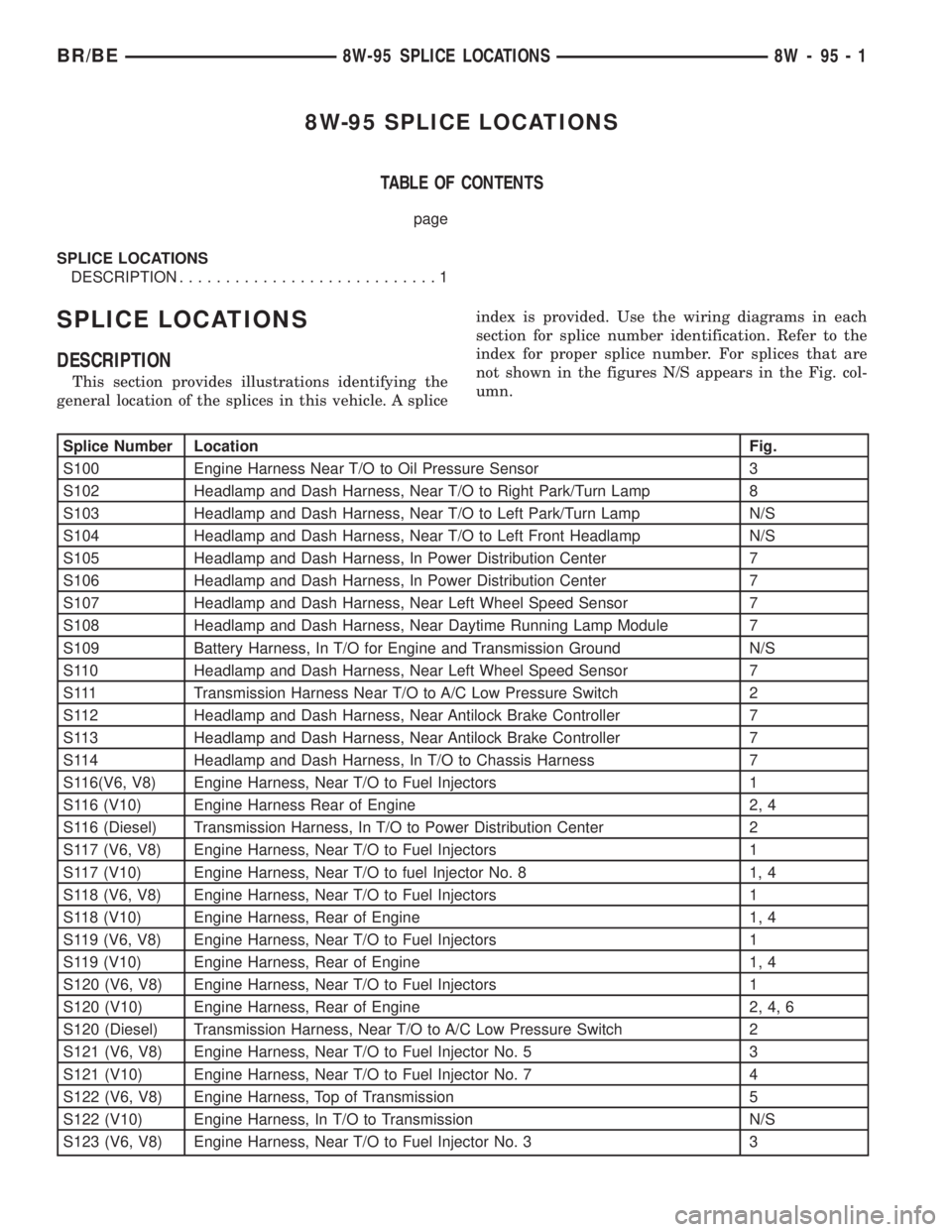
This section provides illustrations identifying the
general location of the splices in this vehicle. A spliceindex is provided. Use the wiring diagrams in each
section for splice number identification. Refer to the
index for proper splice number. For splices that are
not shown in the figures N/S appears in the Fig. col-
umn.
Splice Number Location Fig.
S100 Engine Harness Near T/O to Oil Pressure Sensor 3
S102 Headlamp and Dash Harness, Near T/O to Right Park/Turn Lamp 8
S103 Headlamp and Dash Harness, Near T/O to Left Park/Turn Lamp N/S
S104 Headlamp and Dash Harness, Near T/O to Left Front Headlamp N/S
S105 Headlamp and Dash Harness, In Power Distribution Center 7
S106 Headlamp and Dash Harness, In Power Distribution Center 7
S107 Headlamp and Dash Harness, Near Left Wheel Speed Sensor 7
S108 Headlamp and Dash Harness, Near Daytime Running Lamp Module 7
S109 Battery Harness, In T/O for Engine and Transmission Ground N/S
S110 Headlamp and Dash Harness, Near Left Wheel Speed Sensor 7
S111 Transmission Harness Near T/O to A/C Low Pressure Switch 2
S112 Headlamp and Dash Harness, Near Antilock Brake Controller 7
S113 Headlamp and Dash Harness, Near Antilock Brake Controller 7
S114 Headlamp and Dash Harness, In T/O to Chassis Harness 7
S116(V6, V8) Engine Harness, Near T/O to Fuel Injectors 1
S116 (V10) Engine Harness Rear of Engine 2, 4
S116 (Diesel) Transmission Harness, In T/O to Power Distribution Center 2
S117 (V6, V8) Engine Harness, Near T/O to Fuel Injectors 1
S117 (V10) Engine Harness, Near T/O to fuel Injector No. 8 1, 4
S118 (V6, V8) Engine Harness, Near T/O to Fuel Injectors 1
S118 (V10) Engine Harness, Rear of Engine 1, 4
S119 (V6, V8) Engine Harness, Near T/O to Fuel Injectors 1
S119 (V10) Engine Harness, Rear of Engine 1, 4
S120 (V6, V8) Engine Harness, Near T/O to Fuel Injectors 1
S120 (V10) Engine Harness, Rear of Engine 2, 4, 6
S120 (Diesel) Transmission Harness, Near T/O to A/C Low Pressure Switch 2
S121 (V6, V8) Engine Harness, Near T/O to Fuel Injector No. 5 3
S121 (V10) Engine Harness, Near T/O to Fuel Injector No. 7 4
S122 (V6, V8) Engine Harness, Top of Transmission 5
S122 (V10) Engine Harness, In T/O to Transmission N/S
S123 (V6, V8) Engine Harness, Near T/O to Fuel Injector No. 3 3
BR/BE8W-95 SPLICE LOCATIONS 8W - 95 - 1
Page 1125 of 2889
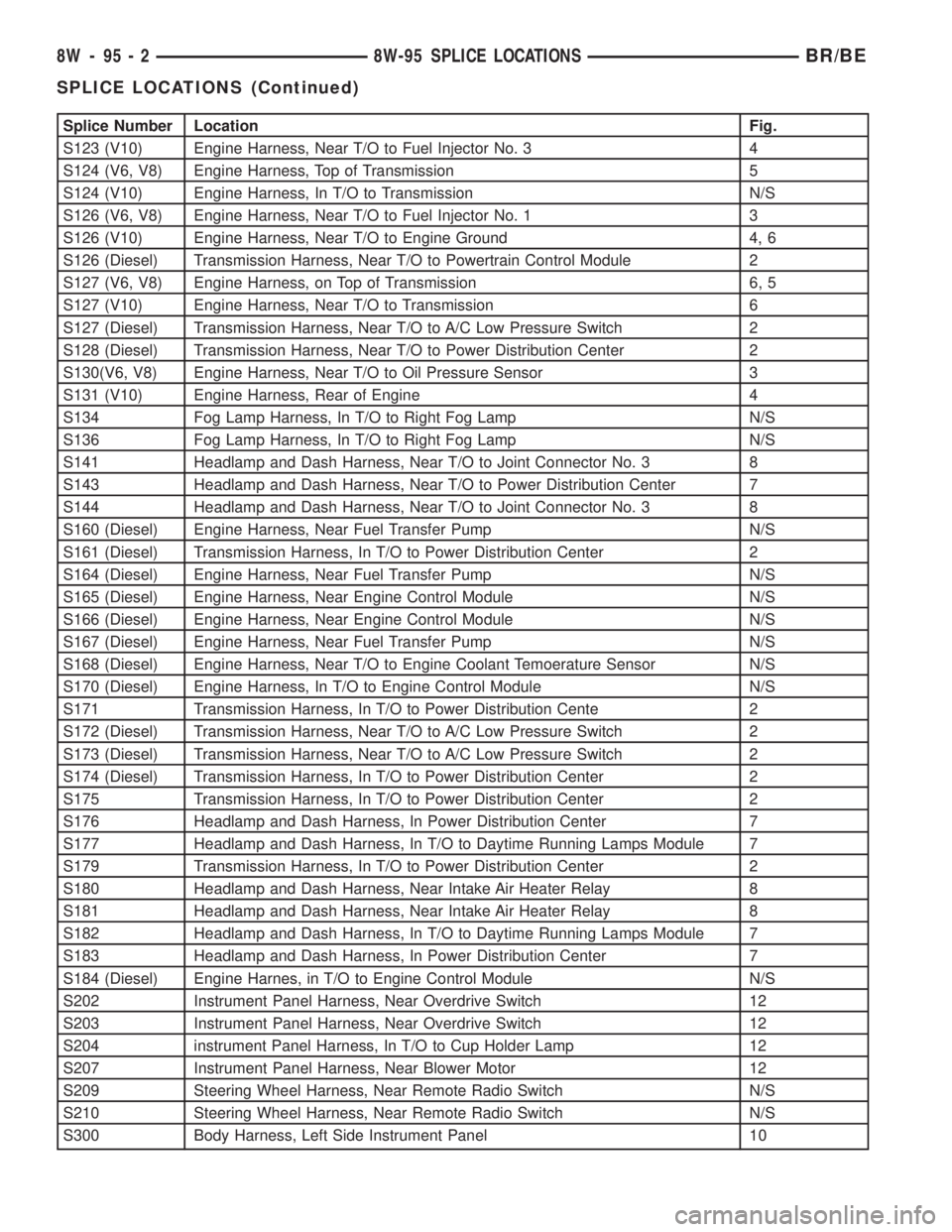
Splice Number Location Fig.
S123 (V10) Engine Harness, Near T/O to Fuel Injector No. 3 4
S124 (V6, V8) Engine Harness, Top of Transmission 5
S124 (V10) Engine Harness, In T/O to Transmission N/S
S126 (V6, V8) Engine Harness, Near T/O to Fuel Injector No. 1 3
S126 (V10) Engine Harness, Near T/O to Engine Ground 4, 6
S126 (Diesel) Transmission Harness, Near T/O to Powertrain Control Module 2
S127 (V6, V8) Engine Harness, on Top of Transmission 6, 5
S127 (V10) Engine Harness, Near T/O to Transmission 6
S127 (Diesel) Transmission Harness, Near T/O to A/C Low Pressure Switch 2
S128 (Diesel) Transmission Harness, Near T/O to Power Distribution Center 2
S130(V6, V8) Engine Harness, Near T/O to Oil Pressure Sensor 3
S131 (V10) Engine Harness, Rear of Engine 4
S134 Fog Lamp Harness, In T/O to Right Fog Lamp N/S
S136 Fog Lamp Harness, In T/O to Right Fog Lamp N/S
S141 Headlamp and Dash Harness, Near T/O to Joint Connector No. 3 8
S143 Headlamp and Dash Harness, Near T/O to Power Distribution Center 7
S144 Headlamp and Dash Harness, Near T/O to Joint Connector No. 3 8
S160 (Diesel) Engine Harness, Near Fuel Transfer Pump N/S
S161 (Diesel) Transmission Harness, In T/O to Power Distribution Center 2
S164 (Diesel) Engine Harness, Near Fuel Transfer Pump N/S
S165 (Diesel) Engine Harness, Near Engine Control Module N/S
S166 (Diesel) Engine Harness, Near Engine Control Module N/S
S167 (Diesel) Engine Harness, Near Fuel Transfer Pump N/S
S168 (Diesel) Engine Harness, Near T/O to Engine Coolant Temoerature Sensor N/S
S170 (Diesel) Engine Harness, In T/O to Engine Control Module N/S
S171 Transmission Harness, In T/O to Power Distribution Cente 2
S172 (Diesel) Transmission Harness, Near T/O to A/C Low Pressure Switch 2
S173 (Diesel) Transmission Harness, Near T/O to A/C Low Pressure Switch 2
S174 (Diesel) Transmission Harness, In T/O to Power Distribution Center 2
S175 Transmission Harness, In T/O to Power Distribution Center 2
S176 Headlamp and Dash Harness, In Power Distribution Center 7
S177 Headlamp and Dash Harness, In T/O to Daytime Running Lamps Module 7
S179 Transmission Harness, In T/O to Power Distribution Center 2
S180 Headlamp and Dash Harness, Near Intake Air Heater Relay 8
S181 Headlamp and Dash Harness, Near Intake Air Heater Relay 8
S182 Headlamp and Dash Harness, In T/O to Daytime Running Lamps Module 7
S183 Headlamp and Dash Harness, In Power Distribution Center 7
S184 (Diesel) Engine Harnes, in T/O to Engine Control Module N/S
S202 Instrument Panel Harness, Near Overdrive Switch 12
S203 Instrument Panel Harness, Near Overdrive Switch 12
S204 instrument Panel Harness, In T/O to Cup Holder Lamp 12
S207 Instrument Panel Harness, Near Blower Motor 12
S209 Steering Wheel Harness, Near Remote Radio Switch N/S
S210 Steering Wheel Harness, Near Remote Radio Switch N/S
S300 Body Harness, Left Side Instrument Panel 10
8W - 95 - 2 8W-95 SPLICE LOCATIONSBR/BE
SPLICE LOCATIONS (Continued)
Page 1143 of 2889
which replace all in-line fusible links. The PDC also
houses up to thirteen blade-type fuses (two standard-
type and eleven mini-type), up to seventeen Interna-
tional Standards Organization (ISO) relays (five
standard-type and twelve micro-type), two joint con-
nectors (one eighteen-way and one twenty-eight-way),
a forty-three-way engine wire harness in-line connec-
tor and a fuse puller.
The PDC housing is secured in the engine compart-
ment on the outboard side with two screws to the left
front inner fender shield, and with a screw on the
inboard side to the left front inner wheel house. The
PDC housing has a molded plastic cover that
includes two integral latches, one on each side. The
PDC cover is easily opened and removed for service
access and has a convenient adhesive-backed fuse
and relay layout map affixed to the inside surface of
the cover to ensure proper component identification.
The PDC unit cannot be repaired and is only ser-
viced as a unit with the headlamp and dash wire
harness. If the internal circuits or the PDC housing
are faulty or damaged, the headlamp and dash wire
harness unit must be replaced.
OPERATION
All of the current from the battery and the gener-
ator output enters the PDC through two cables with
eyelets that are secured with nuts to the two B(+)
terminal studs located just inside the inboard end of
the PDC housing. The PDC cover is unlatched and
removed to access the battery and generator output
connection B(+) terminal studs, the fuses, the relays,
the joint connectors and the engine wire harness in-
line connector. Internal connection of all of the PDC
circuits is accomplished by an intricate combination
of hard wiring and bus bars. Refer toPower Distri-
butionin the index of this service manual for the
location of complete PDC circuit diagrams.
REMOVAL
The Power Distribution Center (PDC) is serviced
as a unit with the headlamp and dash wire harness.
If any internal circuit of the PDC or the PDC hous-
ing is faulty or damaged, the entire PDC and head-
lamp and dash wire harness unit must be replaced.
(1) Disconnect and isolate the battery negative
cable.
(2) Disconnect each of the headlamp and dash wire
harness connectors. Refer toConnector Locations
in the index of this service manual for the location of
more information on the headlamp and dash wire
harness connector locations.
(3) Remove all of the fasteners that secure each of
the headlamp and dash wire harness ground eyelets
to the vehicle body and chassis components. Refer to
Connector Locationsin the index of this servicemanual for the location of more information on the
ground eyelet locations.
(4) Disengage each of the retainers that secure the
headlamp and dash wire harness to the vehicle body
and chassis components. Refer toConnector Loca-
tionsin the index of this service manual for the loca-
tion of more information on the headlamp and dash
wire harness retainer locations.
(5) Unlatch and remove the cover from the PDC.
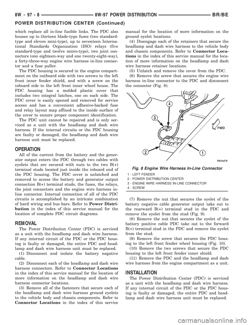
(6) Remove the screw that secures the engine wire
harness in-line connector to the PDC and disconnect
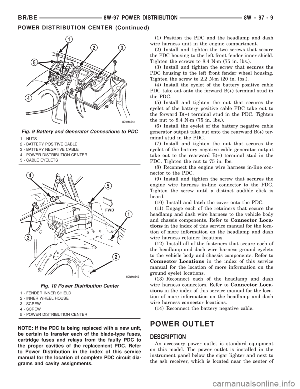
the connector (Fig. 8).
(7) Remove the nut that secures the eyelet of the
battery negative cable generator output take out to
the rearward B(+) terminal stud in the PDC and
remove the eyelet from the stud (Fig. 9).
(8) Remove the nut that secures the eyelet of the
battery positive cable PDC take out to the forward
B(+) terminal stud in the PDC and remove the eyelet
from the stud.
(9) Remove the screw that secures the PDC hous-
ing to the left front fender wheel housing (Fig. 10).
(10) Remove the two screws that secure the PDC
housing to the left front fender inner shield.
(11) Remove the PDC and the headlamp and dash
wire harness from the engine compartment as a unit.
INSTALLATION
The Power Distribution Center (PDC) is serviced
as a unit with the headlamp and dash wire harness.
If any internal circuit of the PDC or the PDC hous-
ing is faulty or damaged, the entire PDC and head-
lamp and dash wire harness unit must be replaced.
Fig. 8 Engine Wire Harness In-Line Connector
1 - LEFT FENDER
2 - POWER DISTRIBUTION CENTER
3 - ENGINE WIRE HARNESS IN-LINE CONNECTOR
4 - SCREW
8W - 97 - 8 8W-97 POWER DISTRIBUTIONBR/BE
POWER DISTRIBUTION CENTER (Continued)
Page 1144 of 2889
NOTE: If the PDC is being replaced with a new unit,
be certain to transfer each of the blade-type fuses,
cartridge fuses and relays from the faulty PDC to
the proper cavities of the replacement PDC. Refer
to Power Distribution in the index of this service
manual for the location of complete PDC circuit dia-
grams and cavity assignments.(1) Position the PDC and the headlamp and dash
wire harness unit in the engine compartment.
(2) Install and tighten the two screws that secure
the PDC housing to the left front fender inner shield.
Tighten the screws to 8.4 N´m (75 in. lbs.).
(3) Install and tighten the screw that secures the
PDC housing to the left front fender wheel housing.
Tighten the screw to 2.2 N´m (20 in. lbs.).
(4) Install the eyelet of the battery positive cable
PDC take out onto the forward B(+) terminal stud in
the PDC.
(5) Install and tighten the nut that secures the
eyelet of the battery positive cable PDC take out to
the forward B(+) terminal stud in the PDC. Tighten
the nut to 8.4 N´m (75 in. lbs.).
(6) Install the eyelet of the battery negative cable
generator output take out onto the rearward B(+) ter-
minal stud in the PDC.
(7) Install and tighten the nut that secures the
eyelet of the battery negative cable generator output
take out to the rearward B(+) terminal stud in the
PDC. Tighten the nut to 75 in. lbs.
(8) Reconnect the engine wire harness in-line con-
nector to the PDC.
(9) Install and tighten the screw that secures the
engine wire harness in-line connector to the PDC.
Tighten the screw until a distinct audible click is
heard.
(10) Install and latch the cover onto the PDC.
(11) Engage each of the retainers that secure the
headlamp and dash wire harness to the vehicle body
and chassis components. Refer toConnector Loca-
tionsin the index of this service manual for the loca-
tion of more information on the headlamp and dash
wire harness retainer locations.
(12) Install all of the fasteners that secure each of
the headlamp and dash wire harness ground eyelets
to the vehicle body and chassis components. Refer to
Connector Locationsin the index of this service
manual for the location of more information on the
ground eyelet locations.
(13) Reconnect each of the headlamp and dash
wire harness connectors. Refer toConnector Loca-
tionsin the index of this service manual for the loca-
tion of more information on the headlamp and dash
wire harness connector locations.
(14) Reconnect the battery negative cable.POWER OUTLET
DESCRIPTION
An accessory power outlet is standard equipment
on this model. The power outlet is installed in the
instrument panel below the cigar lighter and next to
the ash receiver, which is located near the center of
Fig. 9 Battery and Generator Connections to PDC
1 - NUTS
2 - BATTERY POSITIVE CABLE
3 - BATTERY NEGATIVE CABLE
4 - POWER DISTRIBUTION CENTER
5 - CABLE EYELETS
Fig. 10 Power Distribution Center
1 - FENDER INNER SHIELD
2 - INNER WHEEL HOUSE
3 - SCREW
4 - SCREW
5 - POWER DISTRIBUTION CENTER
BR/BE8W-97 POWER DISTRIBUTION 8W - 97 - 9
POWER DISTRIBUTION CENTER (Continued)
Page 2629 of 2889
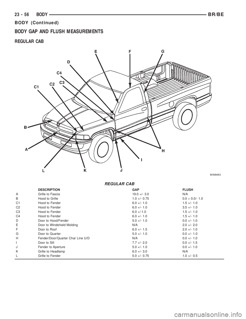
BODY GAP AND FLUSH MEASUREMENTS
REGULAR CAB
REGULAR CAB
DESCRIPTION GAP FLUSH
A Grille to Fascia 19.0 +/- 3.0 N/A
B Hood to Grille 1.0 +/- 0.75 0.0 + 0.0/- 1.0
C1 Hood to Fender 6.0 +/- 1.0 1.5 +/- 1.0
C2 Hood to Fender 6.0 +/- 1.0 3.5 +/- 1.0
C3 Hood to Fender 6.0 +/-1.0 1.5 +/- 1.0
C4 Hood to Fender 6.0 +/- 1.0 1.5 +/- 1.0
D Door to Hood/Fender 5.0 +/- 1.0 0.0 +/- 1.0
E Door to Windshield Molding N/A 2.0 +/- 2.0
F Door to Roof 6.0 +/- 1.5 2.0 +/- 1.0
G Door to Quarter 5.0 +/- 1.0 0.0 +/- 1.0
H Fender/Door/Quarter Char Line U/D N/A 0.0 +/- 1.0
I Door to Sill 7.7 +/- 2.0 0.0 +/- 1.5
J Fender to Aperture 5.0 +/- 1.0 0.0 +/- 1.0
K Grille to Headlamp 6.0 +/- 3.0 N/A
L Grille to Fender 5.0 +/- 0.75 1.0 +/- 0.5
23 - 56 BODYBR/BE
BODY (Continued)
Page 2630 of 2889
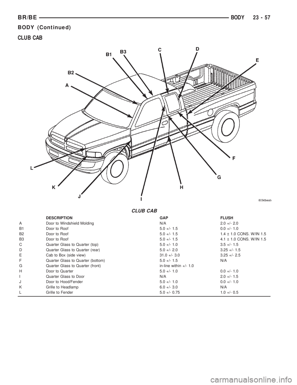
CLUB CAB
CLUB CAB
DESCRIPTION GAP FLUSH
A Door to Windshield Molding N/A 2.0 +/- 2.0
B1 Door to Roof 5.0 +/- 1.5 0.0 +/- 1.0
B2 Door to Roof 5.0 +/- 1.5 1.4 1.0 CONS. W/IN 1.5
B3 Door to Roof 5.0 +/- 1.5 4.1 1.0 CONS. W/IN 1.5
C Quarter Glass to Quarter (top) 5.0 +/- 1.0 3.5 +/- 1.5
D Quarter Glass to Quarter (rear) 5.0 +/- 2.0 3.25 +/- 1.5
E Cab to Box (side view) 31.0 +/- 3.0 3.25 +/- 2.5
F Quarter Glass to Quarter (bottom) 5.0 +/- 1.5 N/A
G Quarter Glass to Quarter (front) in-line within +/- 1.0
H Door to Quarter 5.0 +/- 1.0 0.0 +/- 1.0
I Quarter Glass to Door N/A 2.0 +/- 1.5
J Door to Hood/Fender 5.0 +/- 1.0 0.0 +/- 1.0
K Grille to Headlamp 6.0 +/- 3.0 N/A
L Grille to Fender 5.0 +/- 0.75 1.0 +/- 0.5
BR/BEBODY 23 - 57
BODY (Continued)
Page 2631 of 2889
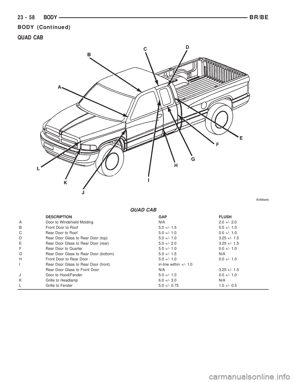
QUAD CAB
QUAD CAB
DESCRIPTION GAP FLUSH
A Door to Windshield Molding N/A 2.0 +/- 2.0
B Front Door to Roof 5.0 +/- 1.5 0.0 +/- 1.0
C Rear Door to Roof 5.0 +/- 1.0 0.0 +/- 1.0
D Rear Door Glass to Rear Door (top) 5.0 +/- 1.0 3.25 +/- 1.5
E Rear Door Glass to Rear Door (rear) 5.0 +/- 2.0 3.25 +/- 1.5
F Rear Door to Quarter 5.5 +/- 1.0 0.0 +/- 1.0
G Rear Door Glass to Rear Door (bottom) 5.0 +/- 1.5 N/A
H Front Door to Rear Door 5.0 +/- 1.0 0.0 +/- 1.0
I Rear Door Glass to Rear Door (front) in-line within +/- 1.0
Rear Door Glass to Front Door N/A 3.25 +/- 1.5
J Door to Hood/Fender 5.0 +/- 1.0 0.0 +/- 1.0
K Grille to Headlamp 6.0 +/- 3.0 N/A
L Grille to Fender 5.0 +/- 0.75 1.0 +/- 0.5
23 - 58 BODYBR/BE
BODY (Continued)
Page 2666 of 2889
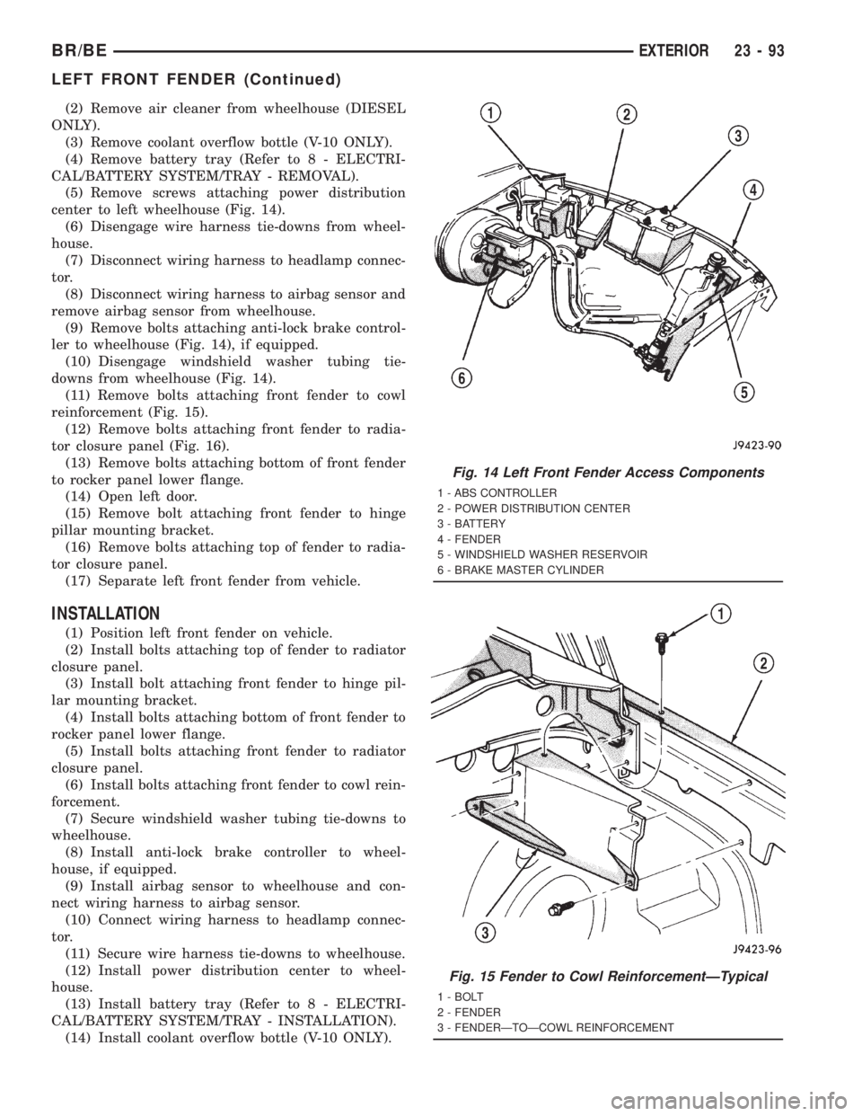
(2) Remove air cleaner from wheelhouse (DIESEL
ONLY).
(3) Remove coolant overflow bottle (V-10 ONLY).
(4) Remove battery tray (Refer to 8 - ELECTRI-
CAL/BATTERY SYSTEM/TRAY - REMOVAL).
(5) Remove screws attaching power distribution
center to left wheelhouse (Fig. 14).
(6) Disengage wire harness tie-downs from wheel-
house.
(7) Disconnect wiring harness to headlamp connec-
tor.
(8) Disconnect wiring harness to airbag sensor and
remove airbag sensor from wheelhouse.
(9) Remove bolts attaching anti-lock brake control-
ler to wheelhouse (Fig. 14), if equipped.
(10) Disengage windshield washer tubing tie-
downs from wheelhouse (Fig. 14).
(11) Remove bolts attaching front fender to cowl
reinforcement (Fig. 15).
(12) Remove bolts attaching front fender to radia-
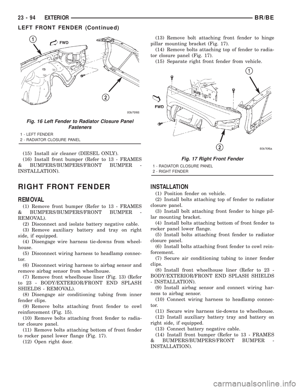
tor closure panel (Fig. 16).
(13) Remove bolts attaching bottom of front fender
to rocker panel lower flange.
(14) Open left door.
(15) Remove bolt attaching front fender to hinge
pillar mounting bracket.
(16) Remove bolts attaching top of fender to radia-
tor closure panel.
(17) Separate left front fender from vehicle.
INSTALLATION
(1) Position left front fender on vehicle.
(2) Install bolts attaching top of fender to radiator
closure panel.
(3) Install bolt attaching front fender to hinge pil-
lar mounting bracket.
(4) Install bolts attaching bottom of front fender to
rocker panel lower flange.
(5) Install bolts attaching front fender to radiator
closure panel.
(6) Install bolts attaching front fender to cowl rein-
forcement.
(7) Secure windshield washer tubing tie-downs to
wheelhouse.
(8) Install anti-lock brake controller to wheel-
house, if equipped.
(9) Install airbag sensor to wheelhouse and con-
nect wiring harness to airbag sensor.
(10) Connect wiring harness to headlamp connec-
tor.
(11) Secure wire harness tie-downs to wheelhouse.
(12) Install power distribution center to wheel-
house.
(13) Install battery tray (Refer to 8 - ELECTRI-
CAL/BATTERY SYSTEM/TRAY - INSTALLATION).
(14) Install coolant overflow bottle (V-10 ONLY).
Fig. 14 Left Front Fender Access Components
1 - ABS CONTROLLER
2 - POWER DISTRIBUTION CENTER
3 - BATTERY
4 - FENDER
5 - WINDSHIELD WASHER RESERVOIR
6 - BRAKE MASTER CYLINDER
Fig. 15 Fender to Cowl ReinforcementÐTypical
1 - BOLT
2 - FENDER
3 - FENDERÐTOÐCOWL REINFORCEMENT
BR/BEEXTERIOR 23 - 93
LEFT FRONT FENDER (Continued)
Page 2667 of 2889
(15) Install air cleaner (DIESEL ONLY).
(16) Install front bumper (Refer to 13 - FRAMES
& BUMPERS/BUMPERS/FRONT BUMPER -
INSTALLATION).
RIGHT FRONT FENDER
REMOVAL
(1) Remove front bumper (Refer to 13 - FRAMES
& BUMPERS/BUMPERS/FRONT BUMPER -
REMOVAL).
(2) Disconnect and isolate battery negative cable.
(3) Remove auxiliary battery and tray on right
side, if equipped.
(4) Disengage wire harness tie-downs from wheel-
house.
(5) Disconnect wiring harness to headlamp connec-
tor.
(6) Disconnect wiring harness to airbag sensor and
remove airbag sensor from wheelhouse.
(7) Remove front wheelhouse liner (Fig. 13) (Refer
to 23 - BODY/EXTERIOR/FRONT END SPLASH
SHIELDS - REMOVAL).
(8) Disengage air conditioning tubing from inner
fender clips.
(9) Remove bolts attaching front fender to cowl
reinforcement (Fig. 15).
(10) Remove bolts attaching front fender to radia-
tor closure panel.
(11) Remove bolts attaching bottom of front fender
to rocker panel lower flange (Fig. 17).
(12) Open right door.(13) Remove bolt attaching front fender to hinge
pillar mounting bracket (Fig. 17).
(14) Remove bolts attaching top of fender to radia-
tor closure panel (Fig. 17).
(15) Separate right front fender from vehicle.
INSTALLATION
(1) Position fender on vehicle.
(2) Install bolts attaching top of fender to radiator
closure panel.
(3) Install bolt attaching front fender to hinge pil-
lar mounting bracket.
(4) Install bolts attaching bottom of front fender to
rocker panel lower flange.
(5) Install bolts attaching front fender to radiator
closure panel.
(6) Install bolts attaching front fender to cowl rein-
forcement.
(7) Secure air conditioning tubing to inner fender
clips.
(8) Install front wheelhouse liner (Refer to 23 -
BODY/EXTERIOR/FRONT END SPLASH SHIELDS
- INSTALLATION).
(9) Install airbag sensor and connect wiring har-
ness to airbag sensor.
(10) Connect wiring harness to headlamp connec-
tor.
(11) Secure wire harness tie-downs to wheelhouse.
(12) Install auxiliary battery tray and battery on
right side, if equipped.
(13) Connect battery negative cable.
(14) Install front bumper (Refer to 13 - FRAMES
& BUMPERS/BUMPERS/FRONT BUMPER -
INSTALLATION).
Fig. 16 Left Fender to Radiator Closure Panel
Fasteners
1 - LEFT FENDER
2 - RADIATOR CLOSURE PANEL
Fig. 17 Right Front Fender
1 - RADIATOR CLOSURE PANEL
2 - RIGHT FENDER
23 - 94 EXTERIORBR/BE
LEFT FRONT FENDER (Continued)