sensor DODGE RAM 2001 Service Manual PDF
[x] Cancel search | Manufacturer: DODGE, Model Year: 2001, Model line: RAM, Model: DODGE RAM 2001Pages: 2889, PDF Size: 68.07 MB
Page 539 of 2889
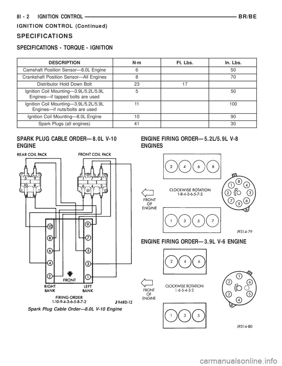
SPECIFICATIONS
SPECIFICATIONS - TORQUE - IGNITION
DESCRIPTION N´m Ft. Lbs. In. Lbs.
Camshaft Position SensorÐ8.0L Engine 6 50
Crankshaft Position SensorÐAll Engines 8 70
Distributor Hold Down Bolt 23 17
Ignition Coil MountingÐ3.9L/5.2L/5.9L
EnginesÐif tapped bolts are used550
Ignition Coil MountingÐ3.9L/5.2L/5.9L
EnginesÐif nuts/bolts are used11 100
Ignition Coil MountingÐ8.0L Engine 10 90
Spark Plugs (all engines) 41 30
SPARK PLUG CABLE ORDERÐ8.0L V-10
ENGINEENGINE FIRING ORDERÐ5.2L/5.9L V-8
ENGINES
ENGINE FIRING ORDERÐ3.9L V-6 ENGINE
Spark Plug Cable OrderÐ8.0L V-10 Engine
8I - 2 IGNITION CONTROLBR/BE
IGNITION CONTROL (Continued)
Page 540 of 2889
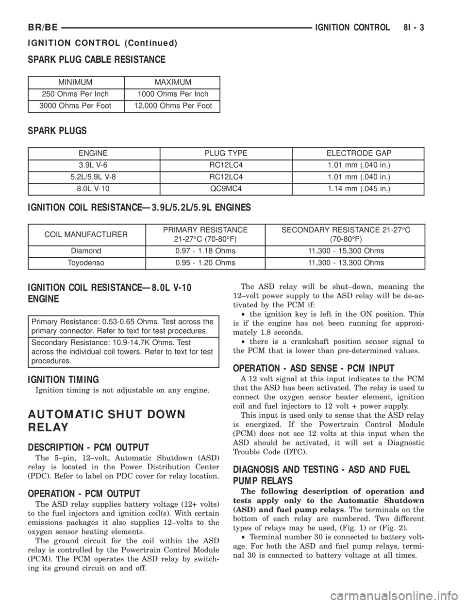
SPARK PLUG CABLE RESISTANCE
MINIMUM MAXIMUM
250 Ohms Per Inch 1000 Ohms Per Inch
3000 Ohms Per Foot 12,000 Ohms Per Foot
SPARK PLUGS
ENGINE PLUG TYPE ELECTRODE GAP
3.9L V-6 RC12LC4 1.01 mm (.040 in.)
5.2L/5.9L V-8 RC12LC4 1.01 mm (.040 in.)
8.0L V-10 QC9MC4 1.14 mm (.045 in.)
IGNITION COIL RESISTANCEÐ3.9L/5.2L/5.9L ENGINES
COIL MANUFACTURERPRIMARY RESISTANCE
21-27ÉC (70-80ÉF)SECONDARY RESISTANCE 21-27ÉC
(70-80ÉF)
Diamond 0.97 - 1.18 Ohms 11,300 - 15,300 Ohms
Toyodenso 0.95 - 1.20 Ohms 11,300 - 13,300 Ohms
IGNITION COIL RESISTANCEÐ8.0L V-10
ENGINE
Primary Resistance: 0.53-0.65 Ohms. Test across the
primary connector. Refer to text for test procedures.
Secondary Resistance: 10.9-14.7K Ohms. Test
across the individual coil towers. Refer to text for test
procedures.
IGNITION TIMING
Ignition timing is not adjustable on any engine.
AUTOMATIC SHUT DOWN
RELAY
DESCRIPTION - PCM OUTPUT
The 5±pin, 12±volt, Automatic Shutdown (ASD)
relay is located in the Power Distribution Center
(PDC). Refer to label on PDC cover for relay location.
OPERATION - PCM OUTPUT
The ASD relay supplies battery voltage (12+ volts)
to the fuel injectors and ignition coil(s). With certain
emissions packages it also supplies 12±volts to the
oxygen sensor heating elements.
The ground circuit for the coil within the ASD
relay is controlled by the Powertrain Control Module
(PCM). The PCM operates the ASD relay by switch-
ing its ground circuit on and off.The ASD relay will be shut±down, meaning the
12±volt power supply to the ASD relay will be de-ac-
tivated by the PCM if:
²the ignition key is left in the ON position. This
is if the engine has not been running for approxi-
mately 1.8 seconds.
²there is a crankshaft position sensor signal to
the PCM that is lower than pre-determined values.
OPERATION - ASD SENSE - PCM INPUT
A 12 volt signal at this input indicates to the PCM
that the ASD has been activated. The relay is used to
connect the oxygen sensor heater element, ignition
coil and fuel injectors to 12 volt + power supply.
This input is used only to sense that the ASD relay
is energized. If the Powertrain Control Module
(PCM) does not see 12 volts at this input when the
ASD should be activated, it will set a Diagnostic
Trouble Code (DTC).
DIAGNOSIS AND TESTING - ASD AND FUEL
PUMP RELAYS
The following description of operation and
tests apply only to the Automatic Shutdown
(ASD) and fuel pump relays. The terminals on the
bottom of each relay are numbered. Two different
types of relays may be used, (Fig. 1) or (Fig. 2).
²Terminal number 30 is connected to battery volt-
age. For both the ASD and fuel pump relays, termi-
nal 30 is connected to battery voltage at all times.
BR/BEIGNITION CONTROL 8I - 3
IGNITION CONTROL (Continued)
Page 542 of 2889
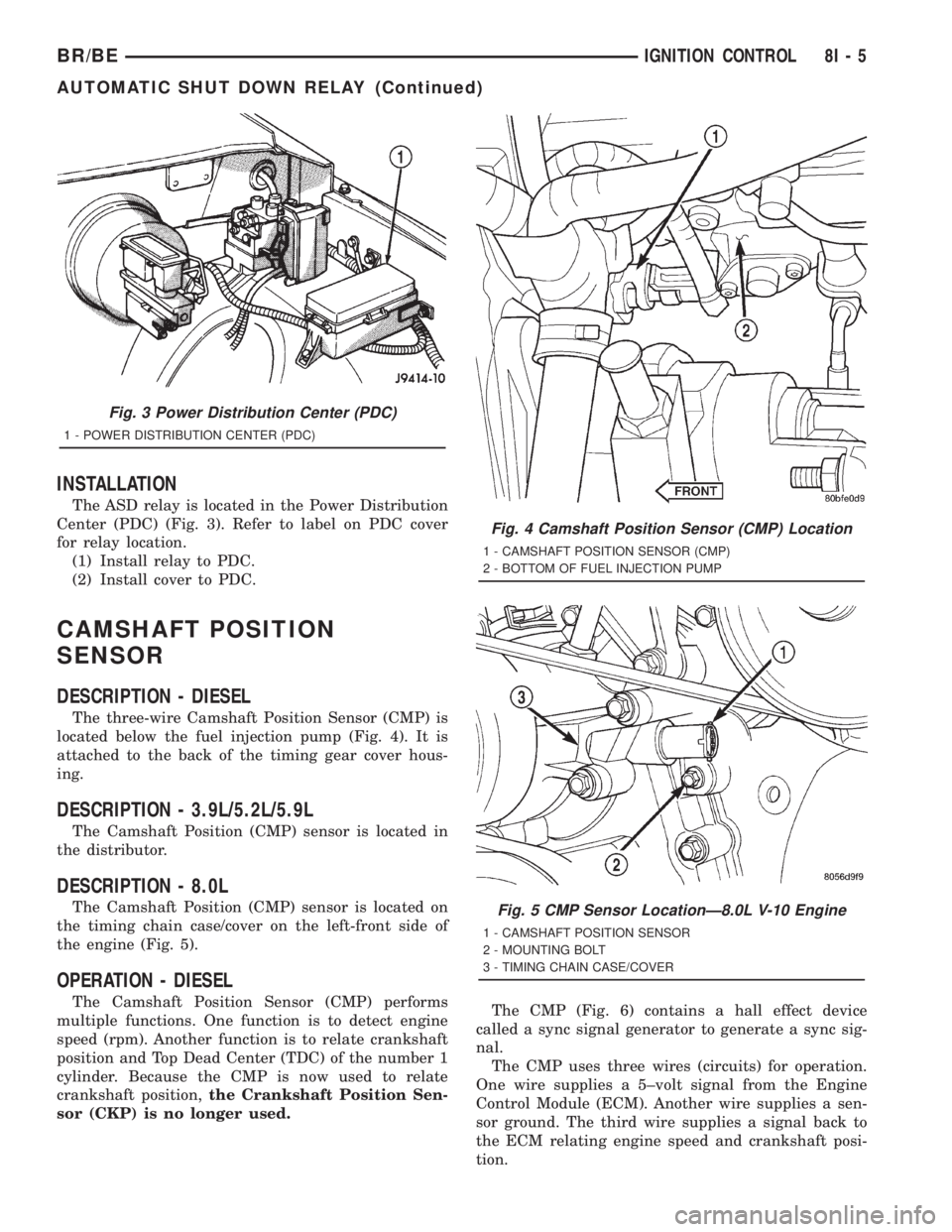
INSTALLATION
The ASD relay is located in the Power Distribution
Center (PDC) (Fig. 3). Refer to label on PDC cover
for relay location.
(1) Install relay to PDC.
(2) Install cover to PDC.
CAMSHAFT POSITION
SENSOR
DESCRIPTION - DIESEL
The three-wire Camshaft Position Sensor (CMP) is
located below the fuel injection pump (Fig. 4). It is
attached to the back of the timing gear cover hous-
ing.
DESCRIPTION - 3.9L/5.2L/5.9L
The Camshaft Position (CMP) sensor is located in
the distributor.
DESCRIPTION - 8.0L
The Camshaft Position (CMP) sensor is located on
the timing chain case/cover on the left-front side of
the engine (Fig. 5).
OPERATION - DIESEL
The Camshaft Position Sensor (CMP) performs
multiple functions. One function is to detect engine
speed (rpm). Another function is to relate crankshaft
position and Top Dead Center (TDC) of the number 1
cylinder. Because the CMP is now used to relate
crankshaft position,the Crankshaft Position Sen-
sor (CKP) is no longer used.The CMP (Fig. 6) contains a hall effect device
called a sync signal generator to generate a sync sig-
nal.
The CMP uses three wires (circuits) for operation.
One wire supplies a 5±volt signal from the Engine
Control Module (ECM). Another wire supplies a sen-
sor ground. The third wire supplies a signal back to
the ECM relating engine speed and crankshaft posi-
tion.
Fig. 3 Power Distribution Center (PDC)
1 - POWER DISTRIBUTION CENTER (PDC)
Fig. 4 Camshaft Position Sensor (CMP) Location
1 - CAMSHAFT POSITION SENSOR (CMP)
2 - BOTTOM OF FUEL INJECTION PUMP
Fig. 5 CMP Sensor LocationÐ8.0L V-10 Engine
1 - CAMSHAFT POSITION SENSOR
2 - MOUNTING BOLT
3 - TIMING CHAIN CASE/COVER
BR/BEIGNITION CONTROL 8I - 5
AUTOMATIC SHUT DOWN RELAY (Continued)
Page 543 of 2889
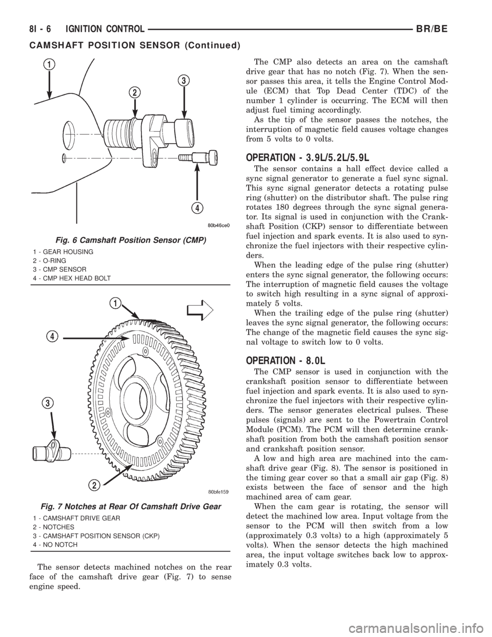
The sensor detects machined notches on the rear
face of the camshaft drive gear (Fig. 7) to sense
engine speed.The CMP also detects an area on the camshaft
drive gear that has no notch (Fig. 7). When the sen-
sor passes this area, it tells the Engine Control Mod-
ule (ECM) that Top Dead Center (TDC) of the
number 1 cylinder is occurring. The ECM will then
adjust fuel timing accordingly.
As the tip of the sensor passes the notches, the
interruption of magnetic field causes voltage changes
from 5 volts to 0 volts.
OPERATION - 3.9L/5.2L/5.9L
The sensor contains a hall effect device called a
sync signal generator to generate a fuel sync signal.
This sync signal generator detects a rotating pulse
ring (shutter) on the distributor shaft. The pulse ring
rotates 180 degrees through the sync signal genera-
tor. Its signal is used in conjunction with the Crank-
shaft Position (CKP) sensor to differentiate between
fuel injection and spark events. It is also used to syn-
chronize the fuel injectors with their respective cylin-
ders.
When the leading edge of the pulse ring (shutter)
enters the sync signal generator, the following occurs:
The interruption of magnetic field causes the voltage
to switch high resulting in a sync signal of approxi-
mately 5 volts.
When the trailing edge of the pulse ring (shutter)
leaves the sync signal generator, the following occurs:
The change of the magnetic field causes the sync sig-
nal voltage to switch low to 0 volts.
OPERATION - 8.0L
The CMP sensor is used in conjunction with the
crankshaft position sensor to differentiate between
fuel injection and spark events. It is also used to syn-
chronize the fuel injectors with their respective cylin-
ders. The sensor generates electrical pulses. These
pulses (signals) are sent to the Powertrain Control
Module (PCM). The PCM will then determine crank-
shaft position from both the camshaft position sensor
and crankshaft position sensor.
A low and high area are machined into the cam-
shaft drive gear (Fig. 8). The sensor is positioned in
the timing gear cover so that a small air gap (Fig. 8)
exists between the face of sensor and the high
machined area of cam gear.
When the cam gear is rotating, the sensor will
detect the machined low area. Input voltage from the
sensor to the PCM will then switch from a low
(approximately 0.3 volts) to a high (approximately 5
volts). When the sensor detects the high machined
area, the input voltage switches back low to approx-
imately 0.3 volts.
Fig. 6 Camshaft Position Sensor (CMP)
1 - GEAR HOUSING
2 - O-RING
3 - CMP SENSOR
4 - CMP HEX HEAD BOLT
Fig. 7 Notches at Rear Of Camshaft Drive Gear
1 - CAMSHAFT DRIVE GEAR
2 - NOTCHES
3 - CAMSHAFT POSITION SENSOR (CKP)
4 - NO NOTCH
8I - 6 IGNITION CONTROLBR/BE
CAMSHAFT POSITION SENSOR (Continued)
Page 544 of 2889
REMOVAL - DIESEL
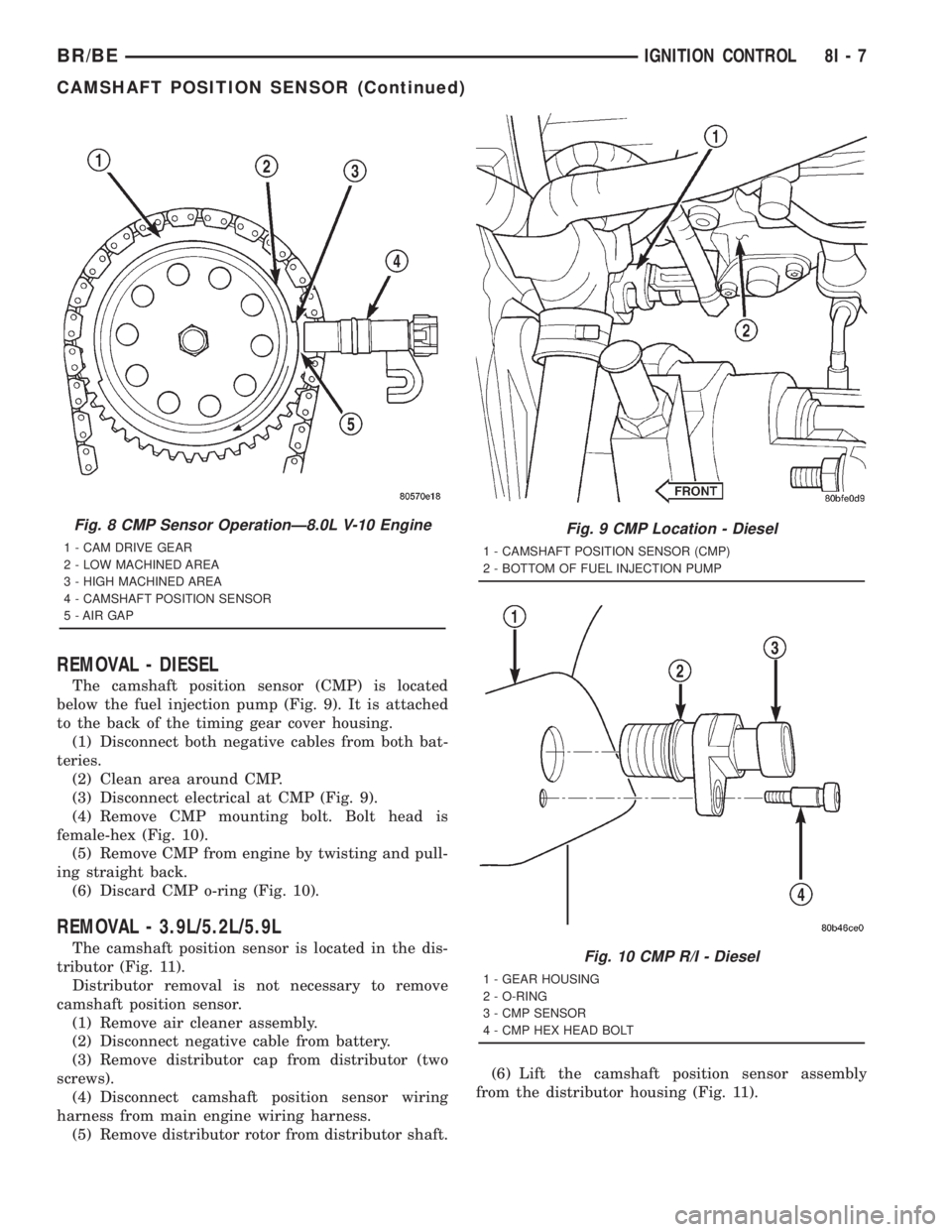
The camshaft position sensor (CMP) is located
below the fuel injection pump (Fig. 9). It is attached
to the back of the timing gear cover housing.
(1) Disconnect both negative cables from both bat-
teries.
(2) Clean area around CMP.
(3) Disconnect electrical at CMP (Fig. 9).
(4) Remove CMP mounting bolt. Bolt head is
female-hex (Fig. 10).
(5) Remove CMP from engine by twisting and pull-
ing straight back.
(6) Discard CMP o-ring (Fig. 10).
REMOVAL - 3.9L/5.2L/5.9L
The camshaft position sensor is located in the dis-
tributor (Fig. 11).
Distributor removal is not necessary to remove
camshaft position sensor.
(1) Remove air cleaner assembly.
(2) Disconnect negative cable from battery.
(3) Remove distributor cap from distributor (two
screws).
(4) Disconnect camshaft position sensor wiring
harness from main engine wiring harness.
(5) Remove distributor rotor from distributor shaft.(6) Lift the camshaft position sensor assembly
from the distributor housing (Fig. 11).
Fig. 8 CMP Sensor OperationÐ8.0L V-10 Engine
1 - CAM DRIVE GEAR
2 - LOW MACHINED AREA
3 - HIGH MACHINED AREA
4 - CAMSHAFT POSITION SENSOR
5 - AIR GAP
Fig. 9 CMP Location - Diesel
1 - CAMSHAFT POSITION SENSOR (CMP)
2 - BOTTOM OF FUEL INJECTION PUMP
Fig. 10 CMP R/I - Diesel
1 - GEAR HOUSING
2 - O-RING
3 - CMP SENSOR
4 - CMP HEX HEAD BOLT
BR/BEIGNITION CONTROL 8I - 7
CAMSHAFT POSITION SENSOR (Continued)
Page 545 of 2889
REMOVAL - 8.0L
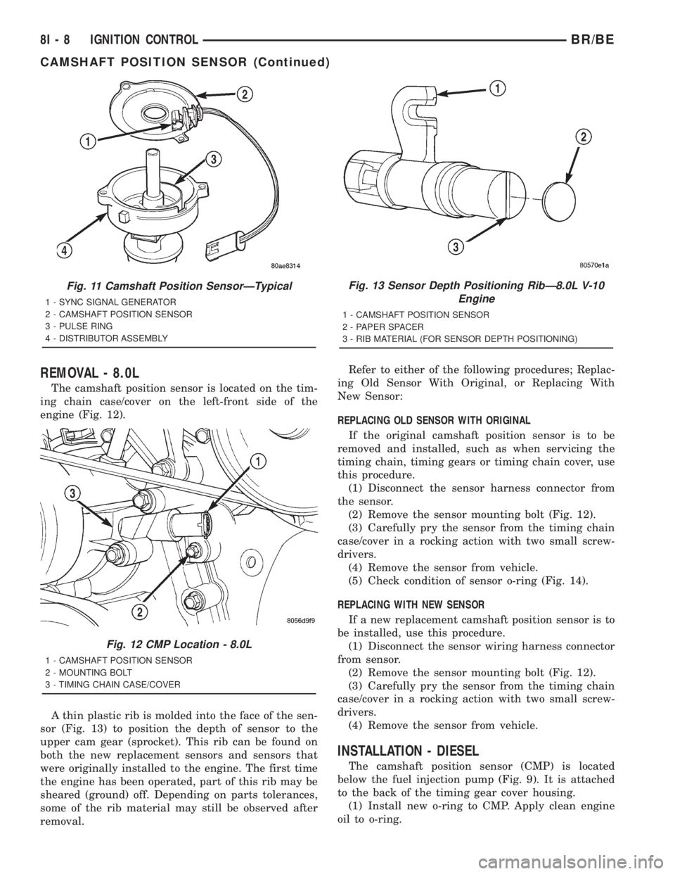
The camshaft position sensor is located on the tim-
ing chain case/cover on the left-front side of the
engine (Fig. 12).
A thin plastic rib is molded into the face of the sen-
sor (Fig. 13) to position the depth of sensor to the
upper cam gear (sprocket). This rib can be found on
both the new replacement sensors and sensors that
were originally installed to the engine. The first time
the engine has been operated, part of this rib may be
sheared (ground) off. Depending on parts tolerances,
some of the rib material may still be observed after
removal.Refer to either of the following procedures; Replac-
ing Old Sensor With Original, or Replacing With
New Sensor:
REPLACING OLD SENSOR WITH ORIGINAL
If the original camshaft position sensor is to be
removed and installed, such as when servicing the
timing chain, timing gears or timing chain cover, use
this procedure.
(1) Disconnect the sensor harness connector from
the sensor.
(2) Remove the sensor mounting bolt (Fig. 12).
(3) Carefully pry the sensor from the timing chain
case/cover in a rocking action with two small screw-
drivers.
(4) Remove the sensor from vehicle.
(5) Check condition of sensor o-ring (Fig. 14).
REPLACING WITH NEW SENSOR
If a new replacement camshaft position sensor is to
be installed, use this procedure.
(1) Disconnect the sensor wiring harness connector
from sensor.
(2) Remove the sensor mounting bolt (Fig. 12).
(3) Carefully pry the sensor from the timing chain
case/cover in a rocking action with two small screw-
drivers.
(4) Remove the sensor from vehicle.
INSTALLATION - DIESEL
The camshaft position sensor (CMP) is located
below the fuel injection pump (Fig. 9). It is attached
to the back of the timing gear cover housing.
(1) Install new o-ring to CMP. Apply clean engine
oil to o-ring.
Fig. 11 Camshaft Position SensorÐTypical
1 - SYNC SIGNAL GENERATOR
2 - CAMSHAFT POSITION SENSOR
3 - PULSE RING
4 - DISTRIBUTOR ASSEMBLY
Fig. 12 CMP Location - 8.0L
1 - CAMSHAFT POSITION SENSOR
2 - MOUNTING BOLT
3 - TIMING CHAIN CASE/COVER
Fig. 13 Sensor Depth Positioning RibÐ8.0L V-10
Engine
1 - CAMSHAFT POSITION SENSOR
2 - PAPER SPACER
3 - RIB MATERIAL (FOR SENSOR DEPTH POSITIONING)
8I - 8 IGNITION CONTROLBR/BE
CAMSHAFT POSITION SENSOR (Continued)
Page 546 of 2889
(2) Clean area around CMP mounting hole.
(3) To prevent tearing o-ring, install CMP into
gear housing using a twisting action.
(4) Install mounting bolt and tighten to 20 Nm (15
ft. lbs.) torque.
(5) Install electrical connector to CMP.
(6) Connect both negative cables to both batteries.
INSTALLATION - 3.9L/5.2L/5.9L
The camshaft position sensor is located in the dis-
tributor (Fig. 11).
(1) Install camshaft position sensor to distributor.
Align sensor into notch on distributor housing.
(2) Connect wiring harness.
(3) Install rotor.
(4) Install distributor cap. Tighten mounting
screws.
(5) Install air cleaner assembly.
INSTALLATION - 8.0L
If Replacing Old Sensor With Original
The camshaft position sensor is located on the tim-
ing chain case/cover on the left-front side of the
engine (Fig. 12).
When installing a used camshaft position sensor,
the sensor depth must be adjusted to prevent contact
with the camshaft gear (sprocket).
(1) Observe the face of the sensor. If any of the
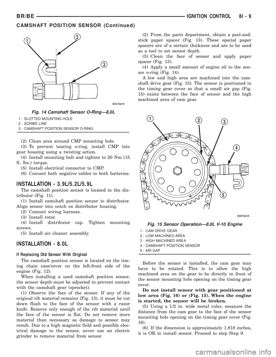
original rib material remains (Fig. 13), it must be cut
down flush to the face of the sensor with a razor
knife. Remove only enough of the rib material until
the face of the sensor is flat. Do not remove more
material than necessary as damage to sensor may
result. Due to a high magnetic field and possible elec-
trical damage to the sensor, never use an electric
grinder to remove material from sensor.(2) From the parts department, obtain a peel-and-
stick paper spacer (Fig. 13). These special paper
spacers are of a certain thickness and are to be used
as a tool to set sensor depth.
(3) Clean the face of sensor and apply paper
spacer (Fig. 13).
(4) Apply a small amount of engine oil to the sen-
sor o-ring (Fig. 14).
A low and high area are machined into the cam-
shaft drive gear (Fig. 15). The sensor is positioned in
the timing gear cover so that a small air gap (Fig.
15) exists between the face of sensor and the high
machined area of cam gear.
Before the sensor is installed, the cam gear may
have to be rotated. This is to allow the high
machined area on the gear to be directly in front of
the sensor mounting hole opening on the timing gear
cover.
Do not install sensor with gear positioned at
low area (Fig. 16) or (Fig. 15). When the engine
is started, the sensor will be broken.
(5) Using a 1/2 in. wide metal ruler, measure the
distance from the cam gear to the face of the sensor
mounting hole opening on the timing gear cover (Fig.
16).
(6) If the dimension is approximately 1.818 inches,
it is OK to install sensor. Proceed to step Step 9.
Fig. 14 Camshaft Sensor O-RingÐ8.0L
1 - SLOTTED MOUNTING HOLE
2 - SCRIBE LINE
3 - CAMSHAFT POSITION SENSOR O-RING
Fig. 15 Sensor OperationÐ8.0L V-10 Engine
1 - CAM DRIVE GEAR
2 - LOW MACHINED AREA
3 - HIGH MACHINED AREA
4 - CAMSHAFT POSITION SENSOR
5 - AIR GAP
BR/BEIGNITION CONTROL 8I - 9
CAMSHAFT POSITION SENSOR (Continued)
Page 547 of 2889
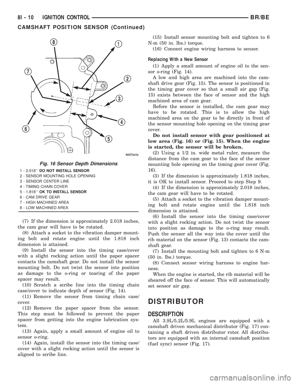
(7) If the dimension is approximately 2.018 inches,
the cam gear will have to be rotated.
(8) Attach a socket to the vibration damper mount-
ing bolt and rotate engine until the 1.818 inch
dimension is attained.
(9) Install the sensor into the timing case/cover
with a slight rocking action until the paper spacer
contacts the camshaft gear. Do not install the sensor
mounting bolt. Do not twist the sensor into position
as damage to the o-ring or tearing of the paper
spacer may result.
(10) Scratch a scribe line into the timing chain
case/cover to indicate depth of sensor (Fig. 14).
(11) Remove the sensor from timing chain case/
cover.
(12) Remove the paper spacer from the sensor.
This step must be followed to prevent the paper
spacer from getting into the engine lubrication sys-
tem.
(13) Again, apply a small amount of engine oil to
sensor o-ring.
(14) Again, install the sensor into the timing case/
cover with a slight rocking action until the sensor is
aligned to scribe line.(15) Install sensor mounting bolt and tighten to 6
N´m (50 in. lbs.) torque.
(16) Connect engine wiring harness to sensor.
Replacing With a New Sensor
(1) Apply a small amount of engine oil to the sen-
sor o-ring (Fig. 14).
A low and high area are machined into the cam-
shaft drive gear (Fig. 15). The sensor is positioned in
the timing gear cover so that a small air gap (Fig.
15) exists between the face of sensor and the high
machined area of cam gear.
Before the sensor is installed, the cam gear may
have to be rotated. This is to allow the high
machined area on the gear to be directly in front of
the sensor mounting hole opening on the timing gear
cover.
Do not install sensor with gear positioned at
low area (Fig. 16) or (Fig. 15). When the engine
is started, the sensor will be broken.
(2) Using a 1/2 in. wide metal ruler, measure the
distance from the cam gear to the face of the sensor
mounting hole opening on the timing gear cover (Fig.
16).
(3) If the dimension is approximately 1.818 inches,
it is OK to install sensor. Proceed to step Step 9.
(4) If the dimension is approximately 2.018 inches,
the cam gear will have to be rotated.
(5) Attach a socket to the vibration damper mount-
ing bolt and rotate engine until the 1.818 inch
dimension is attained.
(6) Install the sensor into the timing case/cover
with a slight rocking action. Do not twist the sensor
into position as damage to the o-ring may result.
Push the sensor all the way into the cover until the
rib material on the sensor (Fig. 13) contacts the cam-
shaft gear.
(7) Install the mounting bolt and tighten to 6 N´m
(50 in. lbs.) torque.
(8) Connect sensor wiring harness to engine har-
ness.
When the engine is started, the rib material will be
sheared off the face of sensor. This will automatically
set sensor air gap.
DISTRIBUTOR
DESCRIPTION
All 3.9L/5.2L/5.9L engines are equipped with a
camshaft driven mechanical distributor (Fig. 17) con-
taining a shaft driven distributor rotor. All distribu-
tors are equipped with an internal camshaft position
(fuel sync) sensor (Fig. 17).
Fig. 16 Sensor Depth Dimensions
1 - 2.01888DO NOT INSTALL SENSOR
2 - SENSOR MOUNTING HOLE OPENING
3 - SENSOR CENTER LINE
4 - TIMING CHAIN COVER
5 - 1.81888OK TO INSTALL SENSOR
6 - CAM DRIVE GEAR
7 - HIGH MACHINED AREA
8 - LOW MACHINED AREA
8I - 10 IGNITION CONTROLBR/BE
CAMSHAFT POSITION SENSOR (Continued)
Page 548 of 2889
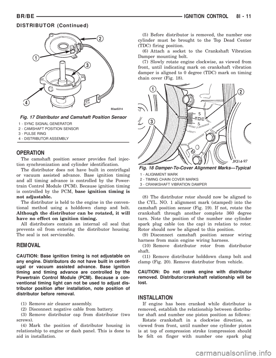
OPERATION
The camshaft position sensor provides fuel injec-
tion synchronization and cylinder identification.
The distributor does not have built in centrifugal
or vacuum assisted advance. Base ignition timing
and all timing advance is controlled by the Power-
train Control Module (PCM). Because ignition timing
is controlled by the PCM,base ignition timing is
not adjustable.
The distributor is held to the engine in the conven-
tional method using a holddown clamp and bolt.
Although the distributor can be rotated, it will
have no effect on ignition timing.
All distributors contain an internal oil seal that
prevents oil from entering the distributor housing.
The seal is not serviceable.
REMOVAL
CAUTION: Base ignition timing is not adjustable on
any engine. Distributors do not have built in centrif-
ugal or vacuum assisted advance. Base ignition
timing and timing advance are controlled by the
Powertrain Control Module (PCM). Because a con-
ventional timing light can not be used to adjust dis-
tributor position after installation, note position of
distributor before removal.
(1) Remove air cleaner assembly.
(2) Disconnect negative cable from battery.
(3) Remove distributor cap from distributor (two
screws).
(4) Mark the position of distributor housing in
relationship to engine or dash panel. This is done to
aid in installation.(5) Before distributor is removed, the number one
cylinder must be brought to the Top Dead Center
(TDC) firing position.
(6) Attach a socket to the Crankshaft Vibration
Damper mounting bolt.
(7) Slowly rotate engine clockwise, as viewed from
front, until indicating mark on crankshaft vibration
damper is aligned to 0 degree (TDC) mark on timing
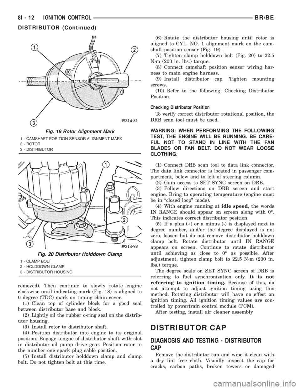
chain cover (Fig. 18).
(8) The distributor rotor should now be aligned to
the CYL. NO. 1 alignment mark (stamped) into the
camshaft position sensor (Fig. 19). If not, rotate the
crankshaft through another complete 360 degree
turn. Note the position of the number one cylinder
spark plug cable (on the cap) in relation to rotor.
Rotor should now be aligned to this position.
(9) Disconnect camshaft position sensor wiring
harness from main engine wiring harness.
(10) Remove distributor rotor from distributor
shaft.
(11) Remove distributor holddown clamp bolt and
clamp (Fig. 20). Remove distributor from vehicle.
CAUTION: Do not crank engine with distributor
removed. Distributor/crankshaft relationship will be
lost.
INSTALLATION
If engine has been cranked while distributor is
removed, establish the relationship between distribu-
tor shaft and number one piston position as follows:
Rotate crankshaft in a clockwise direction, as
viewed from front, until number one cylinder piston
is at top of compression stroke (compression should
be felt on finger with number one spark plug
Fig. 17 Distributor and Camshaft Position Sensor
1 - SYNC SIGNAL GENERATOR
2 - CAMSHAFT POSITION SENSOR
3 - PULSE RING
4 - DISTRIBUTOR ASSEMBLY
Fig. 18 Damper-To-Cover Alignment MarksÐTypical
1 - ALIGNMENT MARK
2 - TIMING CHAIN COVER MARKS
3 - CRANKSHAFT VIBRATION DAMPER
BR/BEIGNITION CONTROL 8I - 11
DISTRIBUTOR (Continued)
Page 549 of 2889
removed). Then continue to slowly rotate engine
clockwise until indicating mark (Fig. 18) is aligned to
0 degree (TDC) mark on timing chain cover.
(1) Clean top of cylinder block for a good seal
between distributor base and block.
(2) Lightly oil the rubber o-ring seal on the distrib-
utor housing.
(3) Install rotor to distributor shaft.
(4) Position distributor into engine to its original
position. Engage tongue of distributor shaft with slot
in distributor oil pump drive gear. Position rotor to
the number one spark plug cable position.
(5) Install distributor holddown clamp and clamp
bolt. Do not tighten bolt at this time.(6) Rotate the distributor housing until rotor is
aligned to CYL. NO. 1 alignment mark on the cam-
shaft position sensor (Fig. 19) .
(7) Tighten clamp holddown bolt (Fig. 20) to 22.5
N´m (200 in. lbs.) torque.
(8) Connect camshaft position sensor wiring har-
ness to main engine harness.
(9) Install distributor cap. Tighten mounting
screws.
(10) Refer to the following, Checking Distributor
Position.
Checking Distributor Position
To verify correct distributor rotational position, the
DRB scan tool must be used.
WARNING: WHEN PERFORMING THE FOLLOWING
TEST, THE ENGINE WILL BE RUNNING. BE CARE-
FUL NOT TO STAND IN LINE WITH THE FAN
BLADES OR FAN BELT. DO NOT WEAR LOOSE
CLOTHING.
(1) Connect DRB scan tool to data link connector.
The data link connector is located in passenger com-
partment, below and to left of steering column.
(2) Gain access to SET SYNC screen on DRB.
(3) Follow directions on DRB screen and start
engine. Bring to operating temperature (engine must
be in ªclosed loopº mode).
(4) With engine running atidle speed, the words
IN RANGE should appear on screen along with 0É.
This indicates correct distributor position.
(5) If a plus (+) or a minus (-) is displayed next to
degree number, and/or the degree displayed is not
zero, loosen but do not remove distributor holddown
clamp bolt. Rotate distributor until IN RANGE
appears on screen. Continue to rotate distributor
until achieving as close to 0É as possible. After
adjustment, tighten clamp bolt to 22.5 N´m (200 in.
lbs.) torque.
The degree scale on SET SYNC screen of DRB is
referring to fuel synchronization only.It is not
referring to ignition timing.Because of this, do
not attempt to adjust ignition timing using this
method. Rotating distributor will have no effect on
ignition timing. All ignition timing values are con-
trolled by powertrain control module (PCM).
After testing, install air cleaner assembly.
DISTRIBUTOR CAP
DIAGNOSIS AND TESTING - DISTRIBUTOR
CAP
Remove the distributor cap and wipe it clean with
a dry lint free cloth. Visually inspect the cap for
cracks, carbon paths, broken towers or damaged
Fig. 19 Rotor Alignment Mark
1 - CAMSHAFT POSITION SENSOR ALIGNMENT MARK
2 - ROTOR
3 - DISTRIBUTOR
Fig. 20 Distributor Holddown Clamp
1 - CLAMP BOLT
2 - HOLDDOWN CLAMP
3 - DISTRIBUTOR HOUSING
8I - 12 IGNITION CONTROLBR/BE
DISTRIBUTOR (Continued)