hood release DODGE RAM 2002 Service Repair Manual
[x] Cancel search | Manufacturer: DODGE, Model Year: 2002, Model line: RAM, Model: DODGE RAM 2002Pages: 2255, PDF Size: 62.07 MB
Page 546 of 2255
TURN SIGNAL CANCEL CAM
DESCRIPTION
The turn signal cancel cam is concealed within the
steering column below the steering wheel. The turn
signal cancel cam consists of two lobes that are inte-
gral to the lower surface of the clockspring rotor. The
clockspring mechanism provides turn signal cancella-
tion as well as a constant electrical connection
between the horn switch, driver airbag, speed control
switches, and remote radio switches on the steering
wheel and the instrument panel wire harness on the
steering column. The housing of the clockspring is
secured to the steering column and remains station-
ary. The rotor of the clockspring, including the turn
signal cancel cam lobes rotate with the steering
wheel.
The turn signal cancel cam is serviced as a unit
with the clockspring and cannot be repaired. If faulty
or damaged, the entire clockspring unit must be
replaced. (Refer to 8 - ELECTRICAL/RESTRAINTS/
CLOCKSPRING - REMOVAL).
OPERATION
The turn signal cancel cam has two lobes molded
into the lower surface of the clockspring rotor. When
the turn signals are activated by moving the multi-
function switch control stalk to a detent position, a
turn signal cancel actuator is extended from the
inside surface of the multi-function switch housing
toward the center of the steering column and the
turn signal cancel cam. When the steering wheel is
rotated during a turning maneuver, one of the two
turn signal cancel cam lobes will contact the turn sig-
nal cancel actuator. The cancel actuator latches
against the cancel cam rotation in the direction oppo-
site that which is signaled. In other words, if the left
turn signal detent is selected, the lobes of the cancel
cam will ratchet past the cancel actuator when the
steering wheel is rotated to the left, but will unlatch
the cancel actuator as the steering wheel rotates to
the right and returns to center, which will cancel the
turn signal event and release the control stalk from
the detent so it returns to the neutral Off position.
UNDERHOOD LAMP
REMOVAL
(1) Disconnect and isolate the battery negative
cable.
(2) Insert a small flat blade in the access slot
between the lamp base and lamp lens.
(3) Pry the lamp lens upward and remove the
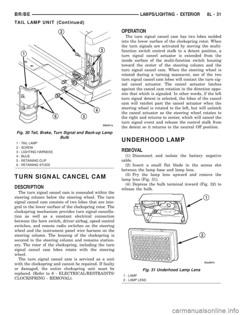
lamp lens (Fig. 31).
(4) Depress the bulb terminal inward (Fig. 32) to
release the bulb.
Fig. 30 Tail, Brake, Turn Signal and Back-up Lamp
Bulb
1 - TAIL LAMP
2 - SCREW
3 - LIGHTING HARNESS
4 - BULB
5 - RETAINING CLIP
6 - RETAINING STUDS
Fig. 31 Underhood Lamp Lens
1 - LAMP
2 - LAMP LENS
BR/BELAMPS/LIGHTING - EXTERIOR 8L - 31
TAIL LAMP UNIT (Continued)
Page 655 of 2255
proper wiper blade travel on the glass. The socket
formation with internal serrations in the wiper arm
pivot end interlocks with the serrations on the outer
circumference of the wiper pivot driver, allowing pos-
itive engagement and finite adjustment of this con-
nection. The latch plate on the underside of the
wiper arm pivot end locks the wiper arm to the wiper
pivot when in its installed position and, when in its
unlocked position, also serves as a blocker to hold the
spring-loaded wiper arm off of the glass to facilitate
removal and installation. The spring-loaded wiper
arm hinge controls the down-force applied through
the tip of the wiper arm to the wiper blade on the
glass. The hook formation on the tip of the wiper arm
provides a cradle for securing and latching the wiper
blade pivot block to the wiper arm.
REMOVAL
(1) Unlatch and open the hood.
(2) Lift the wiper arm far enough to raise the
wiper blade off of the glass and permit the wiper arm
latch plate to be pulled out to its holding position,
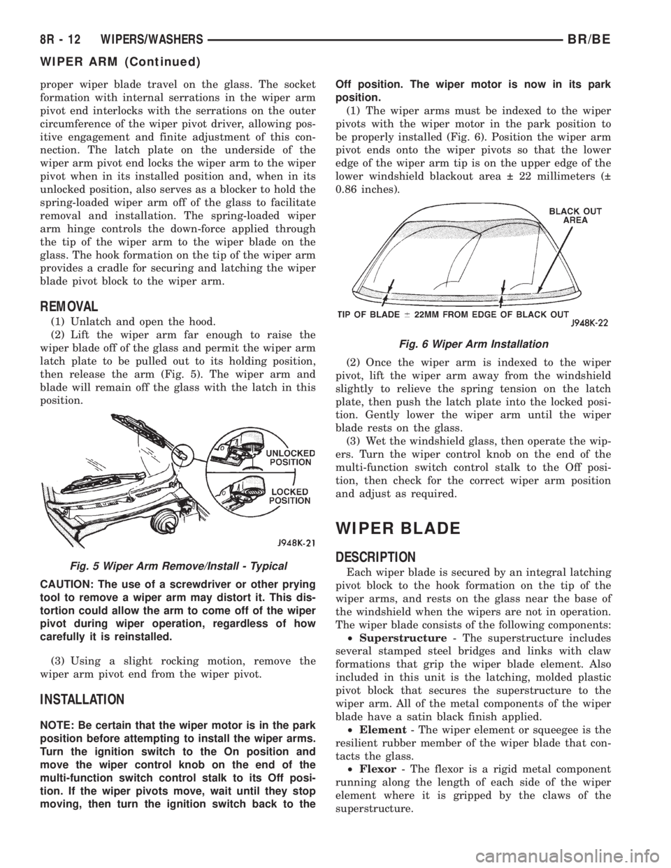
then release the arm (Fig. 5). The wiper arm and
blade will remain off the glass with the latch in this
position.
CAUTION: The use of a screwdriver or other prying
tool to remove a wiper arm may distort it. This dis-
tortion could allow the arm to come off of the wiper
pivot during wiper operation, regardless of how
carefully it is reinstalled.
(3) Using a slight rocking motion, remove the
wiper arm pivot end from the wiper pivot.
INSTALLATION
NOTE: Be certain that the wiper motor is in the park
position before attempting to install the wiper arms.
Turn the ignition switch to the On position and
move the wiper control knob on the end of the
multi-function switch control stalk to its Off posi-
tion. If the wiper pivots move, wait until they stop
moving, then turn the ignition switch back to theOff position. The wiper motor is now in its park
position.
(1) The wiper arms must be indexed to the wiper
pivots with the wiper motor in the park position to
be properly installed (Fig. 6). Position the wiper arm
pivot ends onto the wiper pivots so that the lower
edge of the wiper arm tip is on the upper edge of the
lower windshield blackout area 22 millimeters (
0.86 inches).
(2) Once the wiper arm is indexed to the wiper
pivot, lift the wiper arm away from the windshield
slightly to relieve the spring tension on the latch
plate, then push the latch plate into the locked posi-
tion. Gently lower the wiper arm until the wiper
blade rests on the glass.
(3) Wet the windshield glass, then operate the wip-
ers. Turn the wiper control knob on the end of the
multi-function switch control stalk to the Off posi-
tion, then check for the correct wiper arm position
and adjust as required.
WIPER BLADE
DESCRIPTION
Each wiper blade is secured by an integral latching
pivot block to the hook formation on the tip of the
wiper arms, and rests on the glass near the base of
the windshield when the wipers are not in operation.
The wiper blade consists of the following components:
²Superstructure- The superstructure includes
several stamped steel bridges and links with claw
formations that grip the wiper blade element. Also
included in this unit is the latching, molded plastic
pivot block that secures the superstructure to the
wiper arm. All of the metal components of the wiper
blade have a satin black finish applied.
²Element- The wiper element or squeegee is the
resilient rubber member of the wiper blade that con-
tacts the glass.
²Flexor- The flexor is a rigid metal component
running along the length of each side of the wiper
element where it is gripped by the claws of the
superstructure.Fig. 5 Wiper Arm Remove/Install - Typical
Fig. 6 Wiper Arm Installation
8R - 12 WIPERS/WASHERSBR/BE
WIPER ARM (Continued)
Page 1066 of 2255
tor between many of the engine compartment, instru-
ment panel, and body wire harnesses. The JB houses
up to nineteen blade-type fuses (two standard-type
and seventeen mini-type), up to two blade-type auto-
matic resetting circuit breakers, the electronic combi-
nation turn signal and hazard warning flasher, and
one International Standards Organization (ISO)
micro-relay.
The molded plastic JB housing has integral mount-
ing brackets that are secured with two screws to the
left instrument panel end bracket. The left end of the
instrument panel cover has a snap-fit fuse access
panel that can be removed for service of the JB. A
fuse puller and spare fuse holders are located on the
back of the fuse access cover, as well as an adhesive-
backed fuse layout map to ensure proper fuse identi-
fication.
The JB unit cannot be repaired and is only ser-
viced as an assembly. If any internal circuit or the JB
housing is faulty or damaged, the entire JB unit
must be replaced.
OPERATION
All of the circuits entering and leaving the JB do
so through up to nine wire harness connectors, which
are connected to the JB through integral connector
receptacles molded into the JB housing. Internal con-
nection of all of the JB circuits is accomplished by an
intricate combination of hard wiring and bus bars.
Refer toWiring Diagramsfor the location of com-
plete JB circuit diagrams.
DIAGNOSIS AND TESTING - JUNCTION BLOCK
The junction block does not incorporate any self
diagnostic capability. Most of the electrical circuits
incorporated into the vehicle must pass through the
junction block at one point or another. The most effi-
cient means of diagnosing a suspected junction block
problem involves a simple continuity tester or ohm
meter. Using the Wiring Diagrams as a guide trace
the problem circuit to the proper junction block cav-
ity and test all circuits in the effected circuit for
proper continuity. A open or high resistance circuit is
a sign of a problem. Some other possible junction
block problems to look for are:
²Loose fuse receptacle terminals.
²Loose relay / circuit breaker receptacle termi-
nals.
²Bent or distorted electrical circuit pins.
²Incorrect size fuse installed in junction block
fuse cavity.
²Dark areas identifying a source of excess heat.
²Defective fuse, relay or circuit breaker installed
in junction block cavity.
REMOVAL
(1) Disconnect and isolate the battery negative
cable.
(2) Remove the fuse access bezel from the instru-
ment panel.
(3) Remove the steering column cover (Refer to 23
- BODY/INSTRUMENT PANEL/STEERING COL-
UMN OPENING COVER - REMOVAL).
(4) Remove the hood release handle retaining
screws and position the handle assembly out of the
way.
(5) Remove the lower knee blocker from the instru-
ment panel.
(6) Pull drivers side carpet down, out of the way.
(7) Remove the parking brake switch connector,
release linkage and retaining fasteners and position
the assembly out the drivers door opening.
(8) Remove the electrical ground connections,
located behind park brake mounting location.
(9) Remove the two junction block retaining
screws. To access the upper retaining screw a 15 inch
long #2 Phillips screwdriver will be required. Access
the upper screw through hole in dash support brace.
(10) Reach through the outboard side of the instru-
ment panel steering column opening to access and
disconnect all of the wire harness connectors from
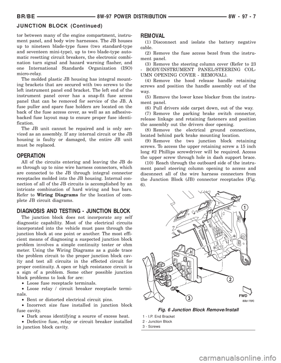
the Junction Block (JB) connector receptacles (Fig.
6).
Fig. 6 Junction Block Remove/Install
1 - I.P. End Bracket
2 - Junction Block
3 - Screws
BR/BE8W-97 POWER DISTRIBUTION 8W - 97 - 7
JUNCTION BLOCK (Continued)
Page 1067 of 2255
(11) Remove the junction block from under the
instrument panel.
INSTALLATION
NOTE: If the Junction Block (JB) is being replaced
with a new unit, be certain to transfer each of the
fuses, circuit breakers and relays from the faulty JB
to the proper cavities of the replacement JB. Refer
to Junction Block in the index of this service man-
ual for the location of complete circuit diagrams
and cavity assignments for the JB.
(1) Position the junction block under the instru-
ment panel.
(2) Connect all of the wire harness connectors on
the Junction Block (JB) connector receptacles.
(3) Install the two junction block retaining screws.
(4) Install the electrical ground connections,
located behind park brake mounting location.
(5) Install the parking brake switch connector,
release linkage and retaining fasteners.
(6) Reposition drivers side carpet.
(7) Install the lower knee blocker on the instru-
ment panel.
(8) Install the hood release handle retaining
screws.
(9) Install the steering column cover.
(10) Install the fuse access bezel on the instrument
panel.
(11) Connect the battery negative cable.
POWER DISTRIBUTION
CENTER
DESCRIPTION
All of the electrical current distributed throughout
this vehicle is directed through the standard equip-
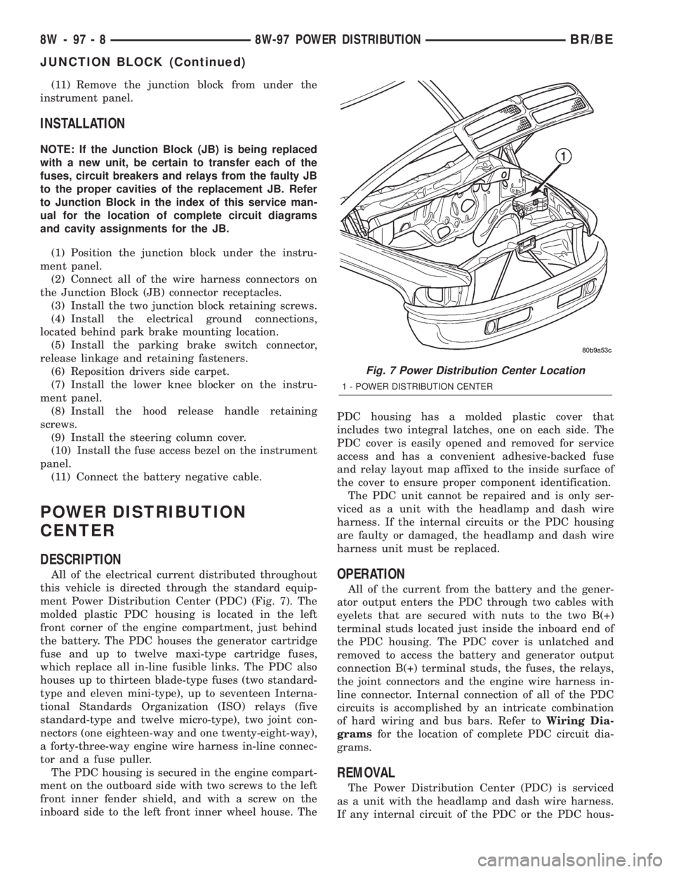
ment Power Distribution Center (PDC) (Fig. 7). The
molded plastic PDC housing is located in the left
front corner of the engine compartment, just behind
the battery. The PDC houses the generator cartridge
fuse and up to twelve maxi-type cartridge fuses,
which replace all in-line fusible links. The PDC also
houses up to thirteen blade-type fuses (two standard-
type and eleven mini-type), up to seventeen Interna-
tional Standards Organization (ISO) relays (five
standard-type and twelve micro-type), two joint con-
nectors (one eighteen-way and one twenty-eight-way),
a forty-three-way engine wire harness in-line connec-
tor and a fuse puller.
The PDC housing is secured in the engine compart-
ment on the outboard side with two screws to the left
front inner fender shield, and with a screw on the
inboard side to the left front inner wheel house. ThePDC housing has a molded plastic cover that
includes two integral latches, one on each side. The
PDC cover is easily opened and removed for service
access and has a convenient adhesive-backed fuse
and relay layout map affixed to the inside surface of
the cover to ensure proper component identification.
The PDC unit cannot be repaired and is only ser-
viced as a unit with the headlamp and dash wire
harness. If the internal circuits or the PDC housing
are faulty or damaged, the headlamp and dash wire
harness unit must be replaced.OPERATION
All of the current from the battery and the gener-
ator output enters the PDC through two cables with
eyelets that are secured with nuts to the two B(+)
terminal studs located just inside the inboard end of
the PDC housing. The PDC cover is unlatched and
removed to access the battery and generator output
connection B(+) terminal studs, the fuses, the relays,
the joint connectors and the engine wire harness in-
line connector. Internal connection of all of the PDC
circuits is accomplished by an intricate combination
of hard wiring and bus bars. Refer toWiring Dia-
gramsfor the location of complete PDC circuit dia-
grams.
REMOVAL
The Power Distribution Center (PDC) is serviced
as a unit with the headlamp and dash wire harness.
If any internal circuit of the PDC or the PDC hous-
Fig. 7 Power Distribution Center Location
1 - POWER DISTRIBUTION CENTER
8W - 97 - 8 8W-97 POWER DISTRIBUTIONBR/BE
JUNCTION BLOCK (Continued)
Page 2029 of 2255
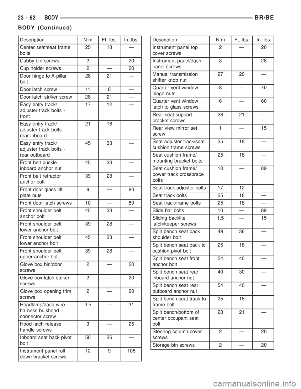
Description N´m Ft. lbs. In. lbs.
Center seat/seat frame
bolts25 18 Ð
Cubby bin screws 2 Ð 20
Cup holder screws 2 Ð 20
Door hinge to A-pillar
bolt28 21 Ð
Door latch screw 11 8 Ð
Door latch striker screw 28 21 Ð
Easy entry track/
adjuster track bolts -
front17 12 Ð
Easy entry track/
adjuster track bolts -
rear inboard21 16 Ð
Easy entry track/
adjuster track bolts -
rear outboard45 33 Ð
Front belt buckle
inboard anchor nut45 33 Ð
Front belt retractor
anchor bolt39 28 Ð
Front door glass lift
plate nuts9Ð80
Front door latch screws 10 Ð 89
Front shoulder belt
anchor bolt45 33 Ð
Front shoulder belt
lower anchor bolt39 28 Ð
Front shoulder belt
lower anchor bolt45 33 Ð
Front shoulder belt
upper anchor bolt39 28 Ð
Glove box bin/door
screws2Ð20
Glove box latch striker
screws2Ð20
Glove box opening trim
screws2Ð20
Headlamp/dash wire
harness bulkhead
connector screw3.5 Ð 31
Hood latch release
handle screws3Ð25
Inboard seat back pivot
bolt50 36 Ð
Instrument panel roll
down bracket screws12 9 105Description N´m Ft. lbs. In. lbs.
Instrument panel top
cover screws2Ð20
Instrument panel/dash
panel screws3Ð28
Manual transmission
shifter knob nut27 20 Ð
Quarter vent window
hinge nuts8Ð70
Quarter vent window
latch to glass screws6Ð60
Rear seat support
bracket screws28 21 Ð
Rear view mirror set
screw1Ð15
Seat adjuster track/seat
cushion frame screws25 18 Ð
Seat cushion frame/
mounting bracket bolts25 18 Ð
Seat cushion frame/
power track crossbrace
bolts10 Ð 89
Seat track adjuster bolts 17 12 Ð
Seat track bolts 25 18 Ð
Seat track/frame bolts 25 18 Ð
Slide bar bolts 10 Ð 89
Sliding backlite
latch/keeper screws1.5 Ð 15
Split bench seat back
shoulder bolt49 36 Ð
Split bench seat back to
cushion pivot bolt25 18 Ð
Split bench seat front
anchor bolt54 40 Ð
Split bench seat rear
inboard anchor nut40 30 Ð
Split bench seat rear
outboard anchor nut54 40 Ð
Split bench seat track to
frame bolt25 18 Ð
Split bench/bottom of
center occupant seat
bolt28 21 Ð
Steering column cover
screws2Ð20
Storage bin screws 2 Ð 20
23 - 62 BODYBR/BE
BODY (Continued)
Page 2058 of 2255
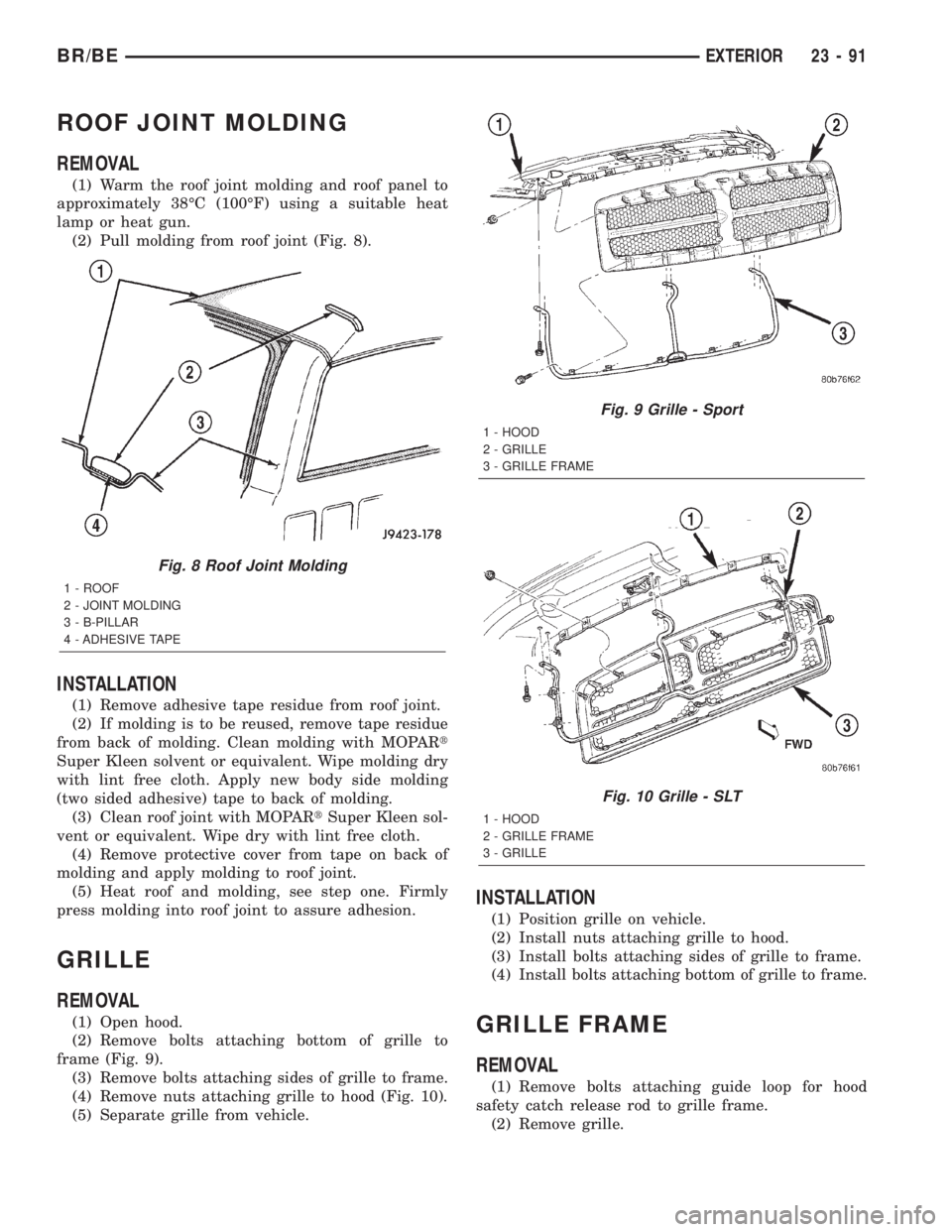
ROOF JOINT MOLDING
REMOVAL
(1) Warm the roof joint molding and roof panel to
approximately 38ÉC (100ÉF) using a suitable heat
lamp or heat gun.
(2) Pull molding from roof joint (Fig. 8).
INSTALLATION
(1) Remove adhesive tape residue from roof joint.
(2) If molding is to be reused, remove tape residue
from back of molding. Clean molding with MOPARt
Super Kleen solvent or equivalent. Wipe molding dry
with lint free cloth. Apply new body side molding
(two sided adhesive) tape to back of molding.
(3) Clean roof joint with MOPARtSuper Kleen sol-
vent or equivalent. Wipe dry with lint free cloth.
(4) Remove protective cover from tape on back of
molding and apply molding to roof joint.
(5) Heat roof and molding, see step one. Firmly
press molding into roof joint to assure adhesion.
GRILLE
REMOVAL
(1) Open hood.
(2) Remove bolts attaching bottom of grille to
frame (Fig. 9).
(3) Remove bolts attaching sides of grille to frame.
(4) Remove nuts attaching grille to hood (Fig. 10).
(5) Separate grille from vehicle.
INSTALLATION
(1) Position grille on vehicle.
(2) Install nuts attaching grille to hood.
(3) Install bolts attaching sides of grille to frame.
(4) Install bolts attaching bottom of grille to frame.
GRILLE FRAME
REMOVAL
(1) Remove bolts attaching guide loop for hood
safety catch release rod to grille frame.
(2) Remove grille.
Fig. 8 Roof Joint Molding
1 - ROOF
2 - JOINT MOLDING
3 - B-PILLAR
4 - ADHESIVE TAPE
Fig. 9 Grille - Sport
1 - HOOD
2 - GRILLE
3 - GRILLE FRAME
Fig. 10 Grille - SLT
1 - HOOD
2 - GRILLE FRAME
3 - GRILLE
BR/BEEXTERIOR 23 - 91
Page 2059 of 2255
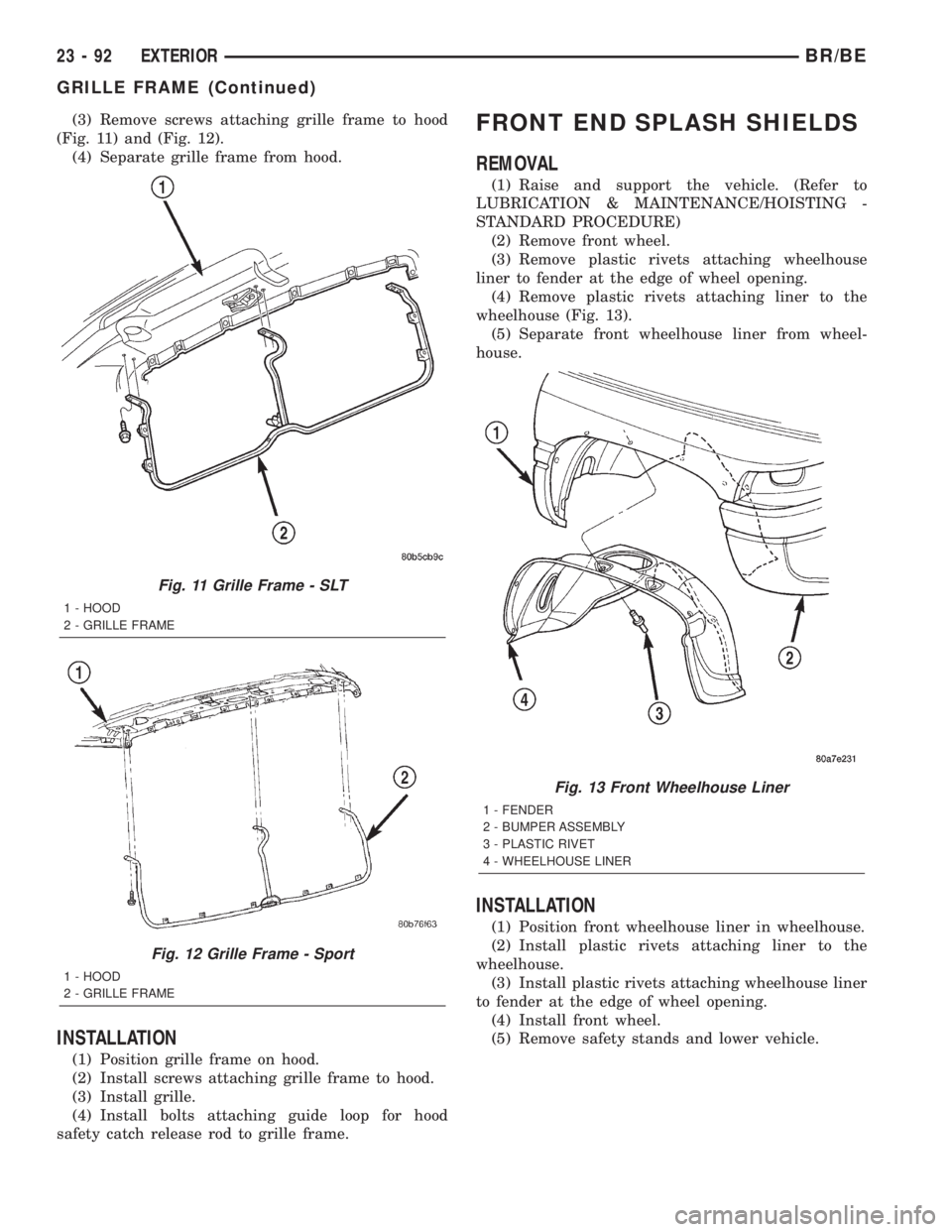
(3) Remove screws attaching grille frame to hood
(Fig. 11) and (Fig. 12).
(4) Separate grille frame from hood.
INSTALLATION
(1) Position grille frame on hood.
(2) Install screws attaching grille frame to hood.
(3) Install grille.
(4) Install bolts attaching guide loop for hood
safety catch release rod to grille frame.
FRONT END SPLASH SHIELDS
REMOVAL
(1) Raise and support the vehicle. (Refer to
LUBRICATION & MAINTENANCE/HOISTING -
STANDARD PROCEDURE)
(2) Remove front wheel.
(3) Remove plastic rivets attaching wheelhouse
liner to fender at the edge of wheel opening.
(4) Remove plastic rivets attaching liner to the
wheelhouse (Fig. 13).
(5) Separate front wheelhouse liner from wheel-
house.
INSTALLATION
(1) Position front wheelhouse liner in wheelhouse.
(2) Install plastic rivets attaching liner to the
wheelhouse.
(3) Install plastic rivets attaching wheelhouse liner
to fender at the edge of wheel opening.
(4) Install front wheel.
(5) Remove safety stands and lower vehicle.
Fig. 11 Grille Frame - SLT
1 - HOOD
2 - GRILLE FRAME
Fig. 12 Grille Frame - Sport
1 - HOOD
2 - GRILLE FRAME
Fig. 13 Front Wheelhouse Liner
1 - FENDER
2 - BUMPER ASSEMBLY
3 - PLASTIC RIVET
4 - WHEELHOUSE LINER
23 - 92 EXTERIORBR/BE
GRILLE FRAME (Continued)
Page 2067 of 2255
HOOD
TABLE OF CONTENTS
page page
HINGE
REMOVAL............................100
INSTALLATION........................100
HOOD
REMOVAL............................101
INSTALLATION........................101
ADJUSTMENTS
ADJUSTMENT.......................101
LATCH
REMOVAL............................102
INSTALLATION........................102
ADJUSTMENTS
ADJUSTMENT.......................102
LATCH RELEASE CABLE
REMOVAL............................103INSTALLATION........................103
LATCH STRIKER
REMOVAL............................103
INSTALLATION........................103
ADJUSTMENTS
ADJUSTMENT.......................103
SAFETY LATCH
REMOVAL............................104
INSTALLATION........................104
SILENCER PAD
REMOVAL............................104
INSTALLATION........................104
HINGE
REMOVAL
(1) Open hood and support the side that requires
hinge replacement.
(2) Mark all bolt and hinge attachment locations
with a grease pencil or equivalent to provide refer-
ence marks for installation.
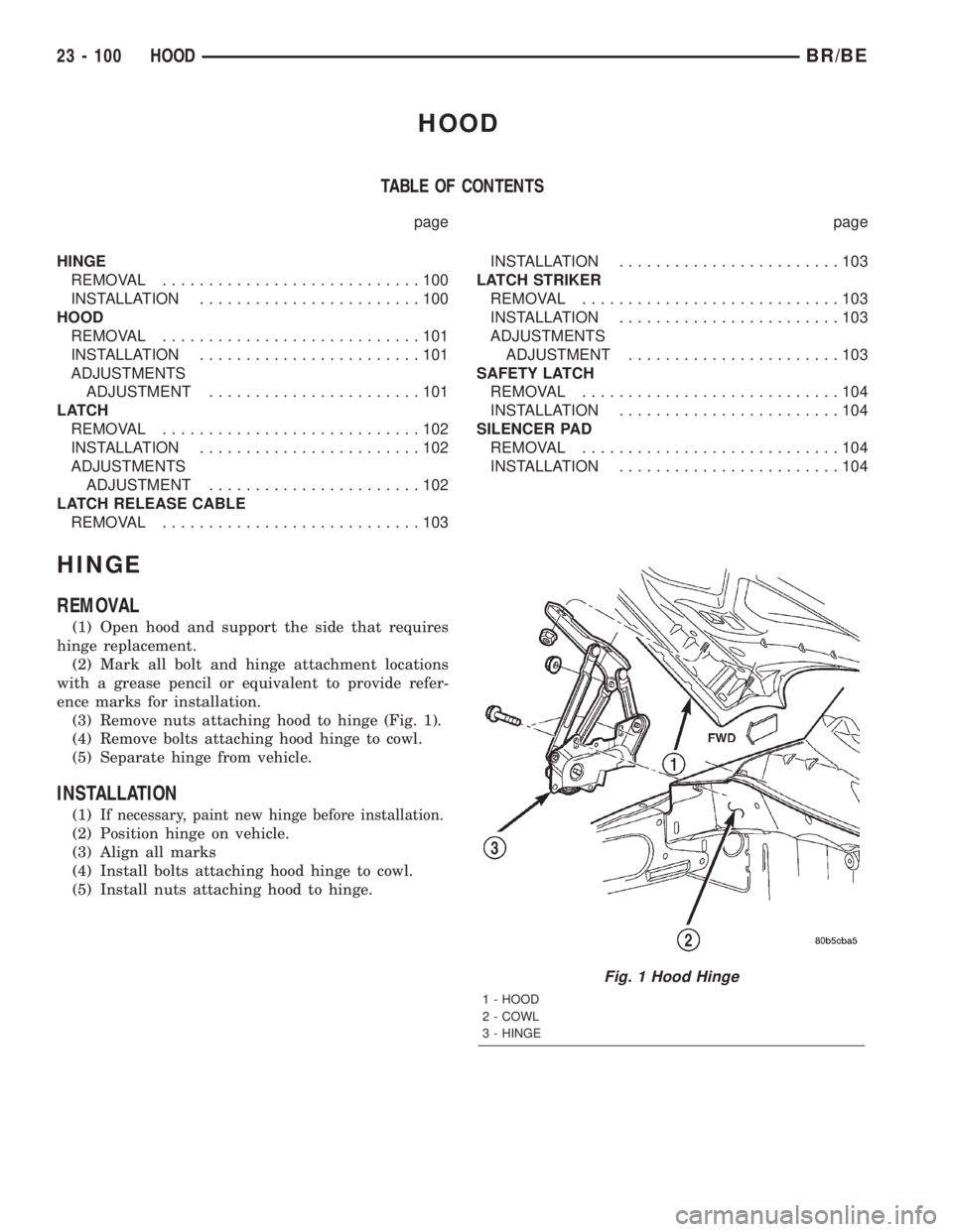
(3) Remove nuts attaching hood to hinge (Fig. 1).
(4) Remove bolts attaching hood hinge to cowl.
(5) Separate hinge from vehicle.
INSTALLATION
(1)If necessary, paint new hinge before installation.
(2) Position hinge on vehicle.
(3) Align all marks
(4) Install bolts attaching hood hinge to cowl.
(5) Install nuts attaching hood to hinge.
Fig. 1 Hood Hinge
1 - HOOD
2 - COWL
3 - HINGE
23 - 100 HOODBR/BE
Page 2069 of 2255
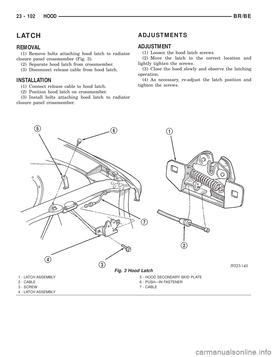
LATCH
REMOVAL
(1) Remove bolts attaching hood latch to radiator
closure panel crossmember (Fig. 3).
(2) Separate hood latch from crossmember.
(3) Disconnect release cable from hood latch.
INSTALLATION
(1) Connect release cable to hood latch.
(2) Position hood latch on crossmember.
(3) Install bolts attaching hood latch to radiator
closure panel crossmember.
ADJUSTMENTS
ADJUSTMENT
(1) Loosen the hood latch screws.
(2) Move the latch to the correct location and
lightly tighten the screws.
(3) Close the hood slowly and observe the latching
operation.
(4) As necessary, re-adjust the latch position and
tighten the screws.
Fig. 3 Hood Latch
1 - LATCH ASSEMBLY
2 - CABLE
3 - SCREW
4 - LATCH ASSEMBLY5 - HOOD SECONDARY SKID PLATE
6 - PUSHÐIN FASTENER
7 - CABLE
23 - 102 HOODBR/BE
Page 2070 of 2255
LATCH RELEASE CABLE
REMOVAL
(1) Remove hood latch (Refer to 23 - BODY/HOOD/
LATCH - REMOVAL).
(2) Disconnect release cable from hood latch.
(3) Detach the release cable from the retainer clips
in the engine compartment.
(4) Separate the release cable grommet from the
dash panel hole.
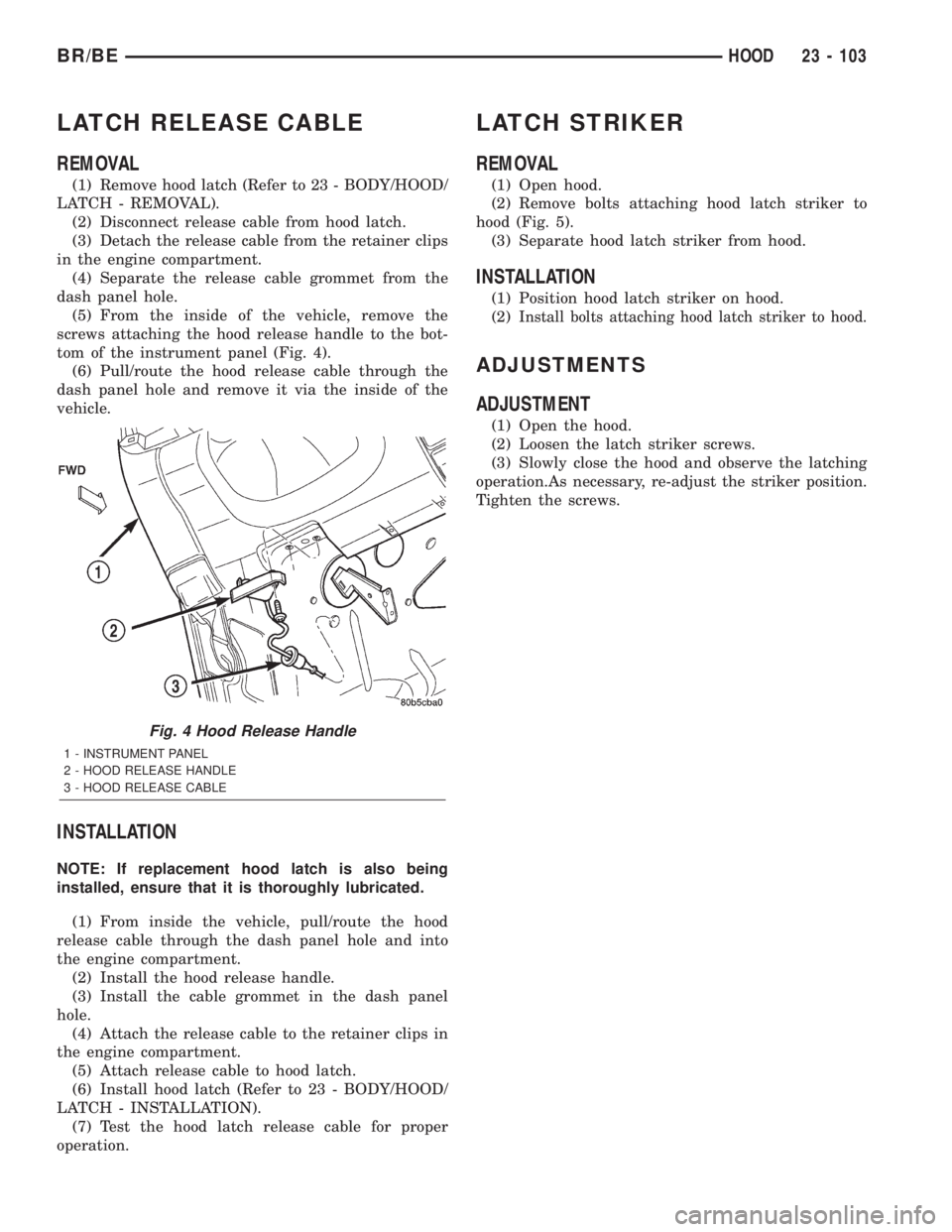
(5) From the inside of the vehicle, remove the
screws attaching the hood release handle to the bot-
tom of the instrument panel (Fig. 4).
(6) Pull/route the hood release cable through the
dash panel hole and remove it via the inside of the
vehicle.
INSTALLATION
NOTE: If replacement hood latch is also being
installed, ensure that it is thoroughly lubricated.
(1) From inside the vehicle, pull/route the hood
release cable through the dash panel hole and into
the engine compartment.
(2) Install the hood release handle.
(3) Install the cable grommet in the dash panel
hole.
(4) Attach the release cable to the retainer clips in
the engine compartment.
(5) Attach release cable to hood latch.
(6) Install hood latch (Refer to 23 - BODY/HOOD/
LATCH - INSTALLATION).
(7) Test the hood latch release cable for proper
operation.
LATCH STRIKER
REMOVAL
(1) Open hood.
(2) Remove bolts attaching hood latch striker to
hood (Fig. 5).
(3) Separate hood latch striker from hood.
INSTALLATION
(1) Position hood latch striker on hood.
(2)
Install bolts attaching hood latch striker to hood.
ADJUSTMENTS
ADJUSTMENT
(1) Open the hood.
(2) Loosen the latch striker screws.
(3) Slowly close the hood and observe the latching
operation.As necessary, re-adjust the striker position.
Tighten the screws.
Fig. 4 Hood Release Handle
1 - INSTRUMENT PANEL
2 - HOOD RELEASE HANDLE
3 - HOOD RELEASE CABLE
BR/BEHOOD 23 - 103