connector diagram DODGE RAM 2003 Service Workshop Manual
[x] Cancel search | Manufacturer: DODGE, Model Year: 2003, Model line: RAM, Model: DODGE RAM 2003Pages: 2895, PDF Size: 83.15 MB
Page 1246 of 2895
INSTALLATION
(1) Turn the ignition switch to the Off position.
(2) Remove the Integrated Power Module cover.
(3) To install the IOD fuse, use a thumb to press
the IOD fuse holder unit in fuse cavity # 51 firmly
into the Integrated Power Module.
(4) Install the Integrated Power Module cover.
POWER OUTLET
DESCRIPTION
Two power outlets are utilized on this model. One
in the instrument panel center lower bezel and the
other in the center console. The power outlet bases
are secured by a snap fit within the instrument
panel or trim panel. A plastic protective cap snaps
into the power outlet base when the power outlet is
not being used, and hangs from the power outlet base
mount by an integral bail strap while the power out-
let is in use.
The power outlet receptacle unit and the accessory
power outlet protective cap are available for service.
The power outlet receptacle cannot be repaired and,
if faulty or damaged, it must be replaced.
OPERATION
The power outlet base or receptacle shell is con-
nected to ground, and an insulated contact in the
bottom of the shell is connected to battery current.
The power outlet receives battery voltage from a fuse
in the integrated power module at all times.
While the power outlet is very similar to a cigar
lighter base unit, it does not include the two small
spring-clip retainers inside the bottom of the recepta-
cle shell that are used to secure the cigar lighter
heating element to the insulated contact.
DIAGNOSIS AND TESTING - POWER OUTLET
For complete circuit diagrams, refer toWiring
Diagrams.
(1) Check the fused B(+) fuse in the integrated
power module. If OK, go to Step 2. If not OK, repair
the shorted circuit or component as required and
replace the faulty fuse.
(2) Check for battery voltage at the fused B(+) fuse
in the integrated power module. If OK, go to Step 3.
If not OK, repair the open fused B(+) circuit to the
battery as required.
(3) Remove the plastic protective cap from the
power outlet receptacle. Check for continuity between
the inside circumference of the power outlet recepta-
cle and a good ground. There should be continuity. If
OK, go to Step 4. If not OK, go to Step 5.(4) Check for battery voltage at the insulated con-
tact located at the back of the power outlet recepta-
cle. If not OK, go to Step 5.
(5) Disconnect and isolate the battery negative
cable. Remove the power outlet receptacle from the
instrument panel. Disconnect the wire harness con-
nector from the power outlet receptacle. Check for
continuity between the ground circuit cavity of the
power outlet wire harness connector and a good
ground. There should be continuity. If OK, go to Step
6. If not OK, repair the open ground circuit to ground
as required.
(6) Connect the battery negative cable. Check for
battery voltage at the fused B(+) circuit cavity of the
power outlet wire harness connector. If OK, replace
the faulty power outlet receptacle. If not OK, repair
the open fused B(+) circuit to the integrated power
module fuse as required.
REMOVAL
(1) Disconnect and isolate the battery negative
cable.
(2) Pull the cigar lighter knob and element out of
the cigar lighter receptacle base, or unsnap the pro-
tective cap from the power outlet receptacle base.
(3) Look inside the cigar lighter or power outlet
receptacle base and note the position of the rectangu-
lar retaining bosses of the mount that secures the
receptacle base to the panel (Fig. 7).
(4) Insert a pair of external snap ring pliers into
the cigar lighter or power outlet receptacle base and
engage the tips of the pliers with the retaining
bosses of the mount.
(5) Squeeze the pliers to disengage the mount
retaining bosses from the receptacle base and, using
a gentle rocking motion, pull the pliers and the
receptacle base out of the mount.
(6) Pull the receptacle base away from the instru-
ment panel far enough to access the instrument
panel wire harness connector.
(7) Disconnect the instrument panel wire harness
connector from the cigar lighter or power outlet
receptacle base connector receptacle.
(8) Remove the cigar lighter or power outlet mount
from the instrument panel.
INSTALLATION
(1) Reconnect the instrument panel wire harness
connector to the cigar lighter or power outlet recep-
tacle base connector receptacle.
(2) Install the cigar lighter or power outlet mount
into the instrument panel.
(3) Align the splines on the outside of the cigar
lighter or power outlet receptacle base connector
receptacle with the grooves on the inside of the
mount.
DR8W-97 POWER DISTRIBUTION 8W - 97 - 7
IOD FUSE (Continued)
Page 1249 of 2895
no continuity between terminals 87 and 30. If OK, go
to Step 3. If not OK, replace the faulty relay.
(3) Resistance between terminals 85 and 86 (elec-
tromagnet) should be 67.5 - 82.5 ohms. If OK, go to
Step 4. If not OK, replace the faulty relay.
(4) Connect a battery to terminals 85 and 86.
There should now be continuity between terminals
30 and 87, and no continuity between terminals 87A
and 30. If OK, reinstall the relay and use a DRB IIIt
scan tool to perform further testing. Refer to the
appropriate diagnostic information.
Refer to the appropriate wiring information. The
wiring information includes wiring diagrams, proper
wire and connector repair procedures, details of wire
harness routing and retention, connector pin-out
information and location views for the various wire
harness connectors, splices and grounds.REMOVAL
(1) Disconnect and isolate the negative battery
cable.
(2) Remove the relay by grasping it firmly and
pulling it straight out from its receptacle. A slight
back and fourth rocking motion may help the
removal process.
INSTALLATION
(1) Align the micro-relay terminals with the termi-
nal cavities in the receptacle.
(2) Push firmly and evenly on the top of the relay
until the terminals are fully seated in the terminal
cavities in the receptacle.
(3) Connect the battery negative cable.
8W - 97 - 10 8W-97 POWER DISTRIBUTIONDR
MICRO RELAY (Continued)
Page 1540 of 2895
(35) Remove the passenger battery ground cable
from the engine block. Remove the driver side bat-
tery ground cable from the engine block.
(36) Remove power steering pump from engine by
removing 3 bolts.
(37) Remove accelerator linkage cover.
(38)
Disconnect cables from APPS if early model build
(39) If late model build,
(40) Disconnect the ECM power connector.
(41) Disconnect the ECM ground wire from the
hydroform screw.
(42) Disconnect the fuel supply and return hoses.
(43) Remove the cylinder head cover. (Refer to 9 -
ENGINE/CYLINDER HEAD/CYLINDER HEAD
COVER(S) - REMOVAL).
(44) Disconnect the 3 injector harness connectors
at the rocker housing. Disconnect the wire harnesses
from the injectors.
(45) Remove the rear engine lift bracket.
(46) Remove cylinder #4, #5, and #6 intake and
exhaust rocker arms, pedestals, and push tubes. Note
the original location for re-assembly.
(47) Loosen #6 fuel line shield bolts and rotate
shield out of the way.
(48)
Remove cylinder #5 and #6 high pressure fuel
lines. Remove the fuel connector tube nut and fuel con-
nector tube. 46. Remove cylinder #5 and #6 fuel injector.
(49) Remove rocker housing.
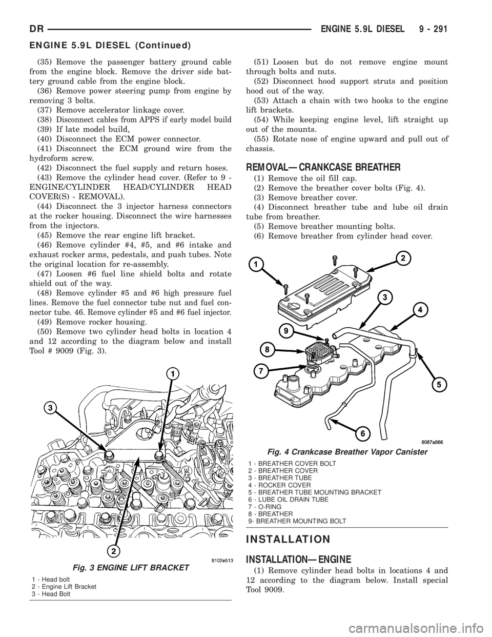
(50) Remove two cylinder head bolts in location 4
and 12 according to the diagram below and install
Tool # 9009 (Fig. 3).(51) Loosen but do not remove engine mount
through bolts and nuts.
(52) Disconnect hood support struts and position
hood out of the way.
(53) Attach a chain with two hooks to the engine
lift brackets.
(54) While keeping engine level, lift straight up
out of the mounts.
(55) Rotate nose of engine upward and pull out of
chassis.
REMOVALÐCRANKCASE BREATHER
(1) Remove the oil fill cap.
(2) Remove the breather cover bolts (Fig. 4).
(3) Remove breather cover.
(4) Disconnect breather tube and lube oil drain
tube from breather.
(5) Remove breather mounting bolts.
(6) Remove breather from cylinder head cover.
INSTALLATION
INSTALLATIONÐENGINE
(1) Remove cylinder head bolts in locations 4 and
12 according to the diagram below. Install special
Tool 9009.Fig. 3 ENGINE LIFT BRACKET
1 - Head bolt
2 - Engine Lift Bracket
3 - Head Bolt
Fig. 4 Crankcase Breather Vapor Canister
1 - BREATHER COVER BOLT
2 - BREATHER COVER
3 - BREATHER TUBE
4 - ROCKER COVER
5 - BREATHER TUBE MOUNTING BRACKET
6 - LUBE OIL DRAIN TUBE
7 - O-RING
8 - BREATHER
9- BREATHER MOUNTING BOLT
DRENGINE 5.9L DIESEL 9 - 291
ENGINE 5.9L DIESEL (Continued)
Page 1804 of 2895
(10) Remove ignition switch mounting screw.
(11) Using a small screwdriver, push on locking
tab and remove switch from steering column.
INSTALLATION
The ignition key must be in the key cylinder for
cylinder removal. The key cylinder must be removed
first before installing ignition switch.
(1) Before installing ignition switch, rotate the slot
in the switch to the ON position.
(2) Connect the electrical connector to rear of the
ignition switch. Make sure that locking tabs are fully
seated into wiring connector.(3) Position switch to column and install the
mounting screw. Tighten screw to 3 N´m (26 in. lbs.).
(4) Install the tilt lever bracket mounting screws.
Tighten screws to 4.5 N´m (40 in. lbs.).
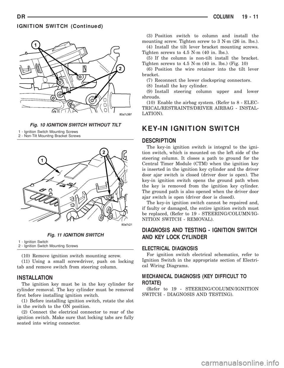
(5) If the column is non-tilt install the bracket.
Tighten screws to 4.5 N´m (40 in. lbs.) (Fig. 10)
(6) Position the wire retainer into the tilt lever
bracket.
(7) Reconnect the lower clockspring connectors.
(8) Install the key cylinder.
(9) Install steering column upper and lower
shrouds.
(10) Enable the airbag system. (Refer to 8 - ELEC-
TRICAL/RESTRAINTS/DRIVER AIRBAG - INSTAL-
LATION).
KEY-IN IGNITION SWITCH
DESCRIPTION
The key-in ignition switch is integral to the igni-
tion switch, which is mounted on the left side of the
steering column. It closes a path to ground for the
Central Timer Module (CTM) when the ignition key
is inserted in the ignition key cylinder and the driver
door ajar switch is closed (driver door is open). The
key-in ignition switch opens the ground path when
the key is removed from the ignition key cylinder.
The ground path is also opened when the driver door
ajar switch is open (driver door is closed).
The key-in ignition switch cannot be repaired and,
if faulty or damaged, the entire ignition switch must
be replaced, (Refer to 19 - STEERING/COLUMN/IG-
NITION SWITCH - REMOVAL).
DIAGNOSIS AND TESTING - IGNITION SWITCH
AND KEY LOCK CYLINDER
ELECTRICAL DIAGNOSIS
For ignition switch electrical schematics, refer to
Ignition Switch in the appropriate section of Electri-
cal Wiring Diagrams.
MECHANICAL DIAGNOSIS (KEY DIFFICULT TO
ROTATE)
(Refer to 19 - STEERING/COLUMN/IGNITION
SWITCH - DIAGNOSIS AND TESTING).
Fig. 10 IGNITION SWITCH WITHOUT TILT
1 - Ignition Switch Mounting Screws
2 - Non-Tilt Mounitng Bracket Screws
Fig. 11 IGNITION SWITCH
1 - Ignition Switch
2 - Ignition Switch Mounting Screws
DRCOLUMN 19 - 11
IGNITION SWITCH (Continued)
Page 2785 of 2895
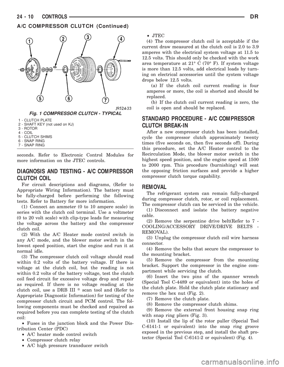
seconds. Refer to Electronic Control Modules for
more information on the JTEC controls.
DIAGNOSIS AND TESTING - A/C COMPRESSOR
CLUTCH COIL
For circuit descriptions and diagrams, (Refer to
Appropriate Wiring Information). The battery must
be fully-charged before performing the following
tests. Refer to Battery for more information.
(1) Connect an ammeter (0 to 10 ampere scale) in
series with the clutch coil terminal. Use a voltmeter
(0 to 20 volt scale) with clip-type leads for measuring
the voltage across the battery and the compressor
clutch coil.
(2) With the A/C Heater mode control switch in
any A/C mode, and the blower motor switch in the
lowest speed position, start the engine and run it at
normal idle.
(3) The compressor clutch coil voltage should read
within 0.2 volts of the battery voltage. If there is
voltage at the clutch coil, but the reading is not
within 0.2 volts of the battery voltage, test the clutch
coil feed circuit for excessive voltage drop and repair
as required. If there is no voltage reading at the
clutch coil, use a DRB IIItscan tool and (Refer to
Appropriate Diagnostic Information) for testing of the
compressor clutch circuit and PCM control. The fol-
lowing components must be checked and repaired as
required before you can complete testing of the clutch
coil:
²Fuses in the junction block and the Power Dis-
tribution Center (PDC)
²A/C heater mode control switch
²Compressor clutch relay
²A/C high pressure transducer switch²JTEC
(4) The compressor clutch coil is acceptable if the
current draw measured at the clutch coil is 2.0 to 3.9
amperes with the electrical system voltage at 11.5 to
12.5 volts. This should only be checked with the work
area temperature at 21É C (70É F). If system voltage
is more than 12.5 volts, add electrical loads by turn-
ing on electrical accessories until the system voltage
drops below 12.5 volts.
(a) If the clutch coil current reading is four
amperes or more, the coil is shorted and should be
replaced.
(b) If the clutch coil current reading is zero, the
coil is open and should be replaced.
STANDARD PROCEDURE - A/C COMPRESSOR
CLUTCH BREAK-IN
After a new compressor clutch has been installed,
cycle the compressor clutch approximately twenty
times (five seconds on, then five seconds off). During
this procedure, set the A/C Heater control to the
Recirculation Mode, the blower motor switch in the
highest speed position, and the engine speed at 1500
to 2000 rpm. This procedure (burnishing) will seat
the opposing friction surfaces and provide a higher
compressor clutch torque capability.
REMOVAL
The refrigerant system can remain fully-charged
during compressor clutch, rotor, or coil replacement.
The compressor clutch can be serviced in the vehicle.
(1) Disconnect and isolate the battery negative
cable.
(2) Remove the serpentine drive belt(Refer to 7 -
COOLING/ACCESSORY DRIVE/DRIVE BELTS -
REMOVAL).
(3) Unplug the compressor clutch coil wire harness
connector.
(4) Remove the bolts that secure the compressor to
the mounting bracket.
(5) Remove the compressor from the mounting
bracket. Support the compressor in the engine com-
partment while servicing the clutch.
(6) Insert the two pins of the spanner wrench
(Special Tool C-4489 or equivalent) into the holes of
the clutch plate. Hold the clutch plate stationary and
remove the hex nut (Fig. 2).
(7) Remove the clutch plate.
(8) Remove the compressor clutch shims.
(9) Remove the external front housing snap ring
with snap ring pliers (Fig. 3).
(10)
Install the lip of the rotor puller (Special Tool
C-6141-1 or equivalent) into the snap ring groove
exposed in the previous step, and install the shaft pro-
tector (Special Tool C-6141-2 or equivalent) (Fig. 4).
Fig. 1 COMPRESSOR CLUTCH - TYPICAL
1 - CLUTCH PLATE
2 - SHAFT KEY (not used on KJ)
3 - ROTOR
4 - COIL
5 - CLUTCH SHIMS
6 - SNAP RING
7 - SNAP RING
24 - 10 CONTROLSDR
A/C COMPRESSOR CLUTCH (Continued)
Page 2788 of 2895
NOTE: The air gap is determined by the spacer
shims. When installing an original, or a new clutch
assembly, try the original shims first. When install-
ing a new clutch onto a compressor that previously
did not have a clutch, use a 1.0, 0.50, and 0.13 mil-
limeter (0.040, 0.020, and 0.005 inch) shims from the
new clutch hardware package that is provided with
the new clutch.
(9) To complete the procedure, (Refer to 24 -
HEATING & AIR CONDITIONING/PLUMBING/A/C
COMPRESSOR - INSTALLATION).
A/C COMPRESSOR CLUTCH
RELAY
DESCRIPTION
The compressor clutch relay is a International
Standards Organization (ISO) micro-relay. The termi-
nal designations and functions are the same as a con-
ventional ISO relay. However, the micro-relay
terminal orientation (footprint) is different, the cur-
rent capacity is lower, and the relay case dimensions
are smaller than those of the conventional ISO relay.
The compressor clutch relay is located in the Power
Distribution Center (PDC) in the engine compart-
ment. Refer to the PDC label for relay identification
and location.
OPERATION
The compressor clutch relay is a electromechanical
device that switches battery current to the compres-
sor clutch coil when the Powertrain Control Module
(PCM) grounds the coil side of the relay. The PCM
responds to inputs from the A/C Heater mode control
switch, the A/C low pressure switch, and the A/C
high pressure switch. (Refer to 24 - HEATING & AIR
CONDITIONING/CONTROLS/A/C COMPRESSOR
CLUTCH RELAY - DIAGNOSIS AND TESTING)
The compressor clutch relay cannot be repaired
and, if faulty or damaged, it must be replaced.
DIAGNOSIS AND TESTING - COMPRESSOR
CLUTCH RELAY
RELAY TEST
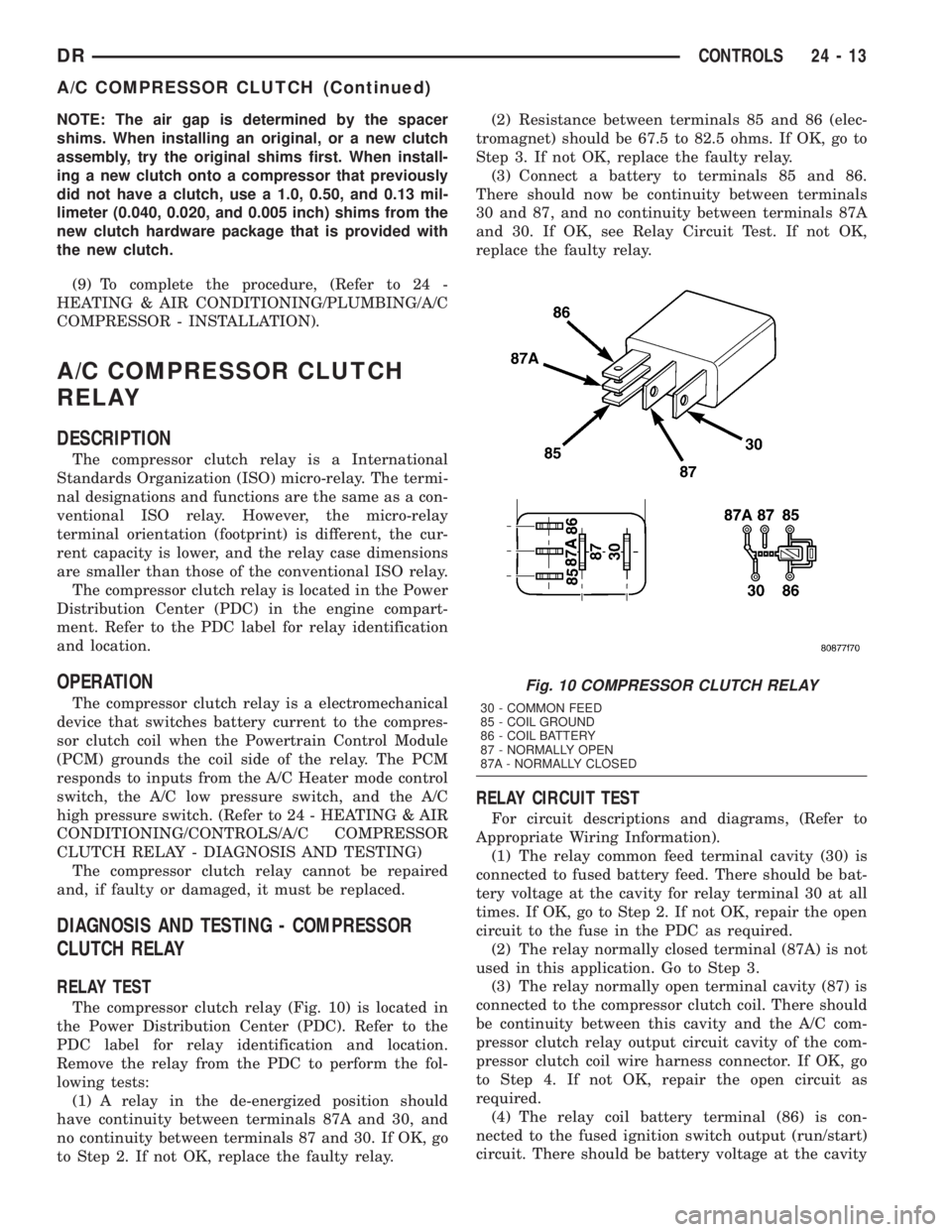
The compressor clutch relay (Fig. 10) is located in
the Power Distribution Center (PDC). Refer to the
PDC label for relay identification and location.
Remove the relay from the PDC to perform the fol-
lowing tests:
(1) A relay in the de-energized position should
have continuity between terminals 87A and 30, and
no continuity between terminals 87 and 30. If OK, go
to Step 2. If not OK, replace the faulty relay.(2) Resistance between terminals 85 and 86 (elec-
tromagnet) should be 67.5 to 82.5 ohms. If OK, go to
Step 3. If not OK, replace the faulty relay.
(3) Connect a battery to terminals 85 and 86.
There should now be continuity between terminals
30 and 87, and no continuity between terminals 87A
and 30. If OK, see Relay Circuit Test. If not OK,
replace the faulty relay.
RELAY CIRCUIT TEST
For circuit descriptions and diagrams, (Refer to
Appropriate Wiring Information).
(1) The relay common feed terminal cavity (30) is
connected to fused battery feed. There should be bat-
tery voltage at the cavity for relay terminal 30 at all
times. If OK, go to Step 2. If not OK, repair the open
circuit to the fuse in the PDC as required.
(2) The relay normally closed terminal (87A) is not
used in this application. Go to Step 3.
(3) The relay normally open terminal cavity (87) is
connected to the compressor clutch coil. There should
be continuity between this cavity and the A/C com-
pressor clutch relay output circuit cavity of the com-
pressor clutch coil wire harness connector. If OK, go
to Step 4. If not OK, repair the open circuit as
required.
(4) The relay coil battery terminal (86) is con-
nected to the fused ignition switch output (run/start)
circuit. There should be battery voltage at the cavity
Fig. 10 COMPRESSOR CLUTCH RELAY
30 - COMMON FEED
85 - COIL GROUND
86 - COIL BATTERY
87 - NORMALLY OPEN
87A - NORMALLY CLOSED
DRCONTROLS 24 - 13
A/C COMPRESSOR CLUTCH (Continued)
Page 2793 of 2895
blower. The blower motor switch directs the ground
path through the correct resistor circuit to obtain the
selected speed.
The blower motor resistor cannot be repaired and,
if faulty or damaged, it must be replaced.
DIAGNOSIS AND TESTING - BLOWER MOTOR
RESISTOR
For circuit descriptions and diagrams, (Refer to
Appropriate Wiring Information).
WARNING: ON VEHICLES EQUIPPED WITH AIR-
BAGS, DISABLE THE AIRBAG SYSTEM BEFORE
ATTEMPTING ANY STEERING WHEEL, STEERING
COLUMN, OR INSTRUMENT PANEL COMPONENT
DIAGNOSIS OR SERVICE. DISCONNECT AND ISO-
LATE THE BATTERY NEGATIVE (GROUND) CABLE,
THEN WAIT TWO MINUTES FOR THE AIRBAG SYS-
TEM CAPACITOR TO DISCHARGE BEFORE PER-
FORMING FURTHER DIAGNOSIS OR SERVICE. THIS
IS THE ONLY SURE WAY TO DISABLE THE AIRBAG
SYSTEM. FAILURE TO TAKE THE PROPER PRE-
CAUTIONS COULD RESULT IN AN ACCIDENTAL
AIRBAG DEPLOYMENT AND POSSIBLE PERSONAL
INJURY.
(1) Disconnect and isolate the battery negative
cable.
(2) Reach under the passenger side bottom of the
HVAC unit and unplug the wire harness connector
from the blower motor resistor.
(3) Check for continuity between each of the
blower motor switch input terminals of the resistor
and the resistor output terminal. In each case there
should be continuity. If OK, repair the wire harness
circuits between the blower motor switch and the
blower motor resistor or blower motor relay as
required. If not OK, replace the faulty blower motor
resistor.
REMOVAL
WARNING: ON VEHICLES EQUIPPED WITH AIR-
BAGS, DISABLE THE AIRBAG SYSTEM BEFORE
ATTEMPTING ANY STEERING WHEEL, STEERING
COLUMN, OR INSTRUMENT PANEL COMPONENT
DIAGNOSIS OR SERVICE. DISCONNECT AND ISO-
LATE THE BATTERY NEGATIVE (GROUND) CABLE,
THEN WAIT TWO MINUTES FOR THE AIRBAG SYS-
TEM CAPACITOR TO DISCHARGE BEFORE PER-
FORMING FURTHER DIAGNOSIS OR SERVICE. THIS
IS THE ONLY SURE WAY TO DISABLE THE AIRBAG
SYSTEM. FAILURE TO TAKE THE PROPER PRE-
CAUTIONS COULD RESULT IN AN ACCIDENTAL
AIRBAG DEPLOYMENT AND POSSIBLE PERSONAL
INJURY.(1) Disconnect and isolate the battery negative
cable.
(2) The blower motor resistor is accessable from
the passenger side of the HVAC unit and is located
on the bottom of the HVAC unit.
(3) Pull out the lock on the blower motor resistor
wire harness connector to unlock the connector latch.
(4) Depress the latch on the blower motor resistor
wire harness connector and unplug the connector
from the resistor.
(5) Remove the two screws that secure the resistor
to the HVAC housing.
(6) Remove the resistor from the HVAC housing.
INSTALLATION
(1) Install the new resistor in the HVAC housing.
(2) Install the two screws that secure the resistor
to the HVAC housing and tighten to 2.2 N´m (20 in.
lbs.).
(3) Plug in the blower motor harness connector.
(4) Push in the lock on the blower motor resistor
harness connector.
(5) Close the glove box door.
(6) Connect the battery negative cable.
BLOWER MOTOR SWITCH
DESCRIPTION
The A/C Heater blower motor is controlled by a
four position rotary-type blower motor switch,
mounted in the A/C Heater control panel. The switch
allows the selection of one of four blower motor
speeds, but can only be turned off by selecting the
Off position on the blower motor switch.
OPERATION
The blower motor switch directs the blower motor
ground path through the mode control switch to the
blower motor resistor, or directly to ground, as
required to achieve the selected blower motor speed.
The blower motor switch cannot be repaired and, if
faulty or damaged, the entire A/C Heater control unit
must be replaced.
DIAGNOSIS AND TESTING - BLOWER MOTOR
SWITCH
For circuit descriptions and diagrams, (Refer to
Appropriate Wiring Information).
24 - 18 CONTROLSDR
BLOWER MOTOR RESISTOR BLOCK (Continued)
Page 2801 of 2895
DIAGNOSIS AND TESTING - BLOWER MOTOR
WARNING: ON VEHICLES EQUIPPED WITH AIR-
BAGS, DISABLE THE AIRBAG SYSTEM BEFORE
ATTEMPTING ANY STEERING WHEEL, STEERING
COLUMN, OR INSTRUMENT PANEL COMPONENT
DIAGNOSIS OR SERVICE. DISCONNECT AND ISO-
LATE THE BATTERY NEGATIVE (GROUND) CABLE,
THEN WAIT TWO MINUTES FOR THE AIRBAG SYS-
TEM CAPACITOR TO DISCHARGE BEFORE PER-
FORMING FURTHER DIAGNOSIS OR SERVICE. THIS
IS THE ONLY SURE WAY TO DISABLE THE AIRBAG
SYSTEM. FAILURE TO TAKE THE PROPER PRE-
CAUTIONS COULD RESULT IN AN ACCIDENTAL
AIRBAG DEPLOYMENT AND POSSIBLE PERSONAL
INJURY.
For circuit descriptions and diagrams, (Refer to
Appropriate Wiring Information). Possible causes of
an inoperative blower motor include:
²Faulty fuse
²Faulty blower motor circuit wiring or wire har-
ness connectors
²Faulty blower motor resistor
²Faulty blower motor relay
²Faulty blower motor switch
²Faulty A/C Heater mode control switch
²Faulty blower motor.
Possible causes of the blower motor not operating
in all speeds include:
²Faulty blower motor switch
²Faulty blower motor resistor
²Faulty blower motor circuit wiring or wire har-
ness connectors.
VIBRATION
Possible causes of blower motor vibration include:
²Improper blower motor mounting
²Improper blower wheel mounting
²Blower wheel out of balance or bent
²Blower motor faulty.
NOISE
To verify that the blower is the source of the noise,
unplug the blower motor wire harness connector and
operate the HVAC system. If the noise goes away,
possible causes include:
²Foreign material in the HVAC housing
²Improper blower motor mounting
²Improper blower wheel mounting
²Blower motor faulty.
REMOVAL
WARNING: ON VEHICLES EQUIPPED WITH AIR-
BAGS, DISABLE THE AIRBAG SYSTEM BEFORE
ATTEMPTING ANY STEERING WHEEL, STEERINGCOLUMN, OR INSTRUMENT PANEL COMPONENT
DIAGNOSIS OR SERVICE. DISCONNECT AND ISO-
LATE THE BATTERY NEGATIVE (GROUND) CABLE,
THEN WAIT TWO MINUTES FOR THE AIRBAG SYS-
TEM CAPACITOR TO DISCHARGE BEFORE PER-
FORMING FURTHER DIAGNOSIS OR SERVICE. THIS
IS THE ONLY SURE WAY TO DISABLE THE AIRBAG
SYSTEM. FAILURE TO TAKE THE PROPER PRE-
CAUTIONS COULD RESULT IN AN ACCIDENTAL
AIRBAG DEPLOYMENT AND POSSIBLE PERSONAL
INJURY.
The blower motor is located on the passenger side
of the vehicle under the dash
(1) Disconnect and isolate the battery negative
cable.
(2) Unplug the blower motor wire harness connec-
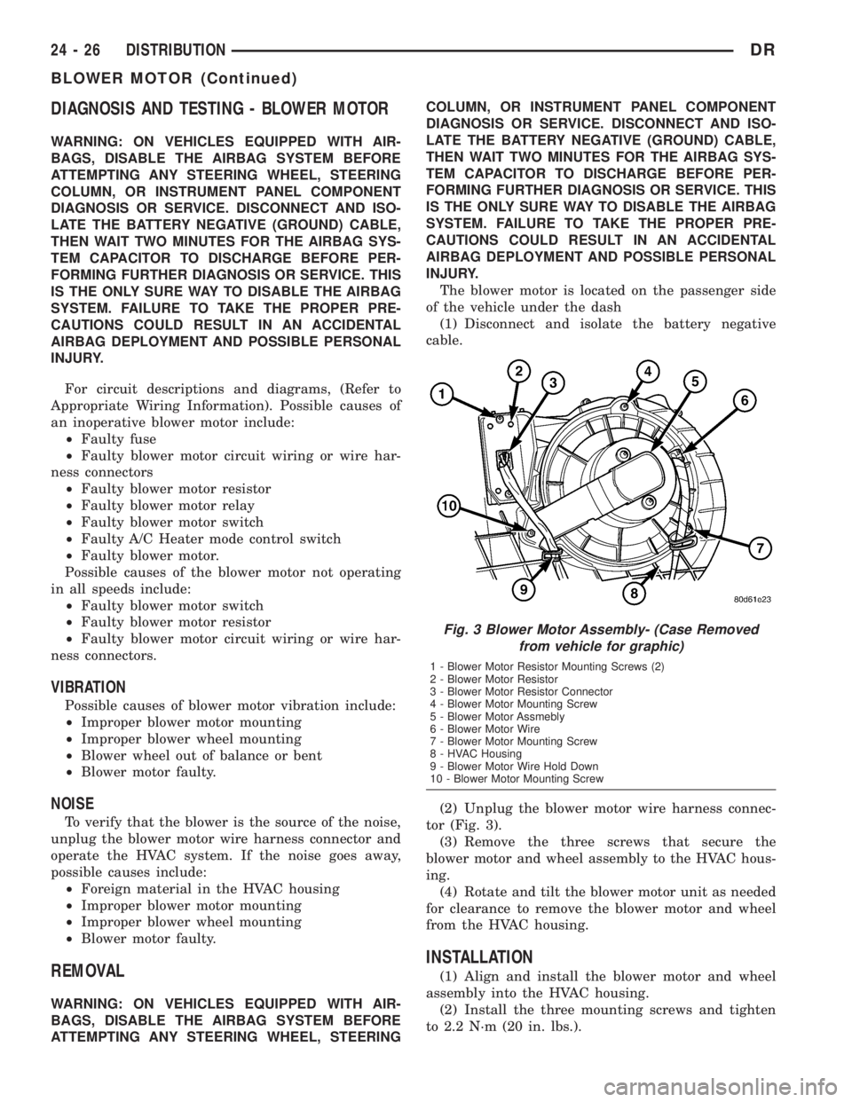
tor (Fig. 3).
(3) Remove the three screws that secure the
blower motor and wheel assembly to the HVAC hous-
ing.
(4) Rotate and tilt the blower motor unit as needed
for clearance to remove the blower motor and wheel
from the HVAC housing.
INSTALLATION
(1) Align and install the blower motor and wheel
assembly into the HVAC housing.
(2) Install the three mounting screws and tighten
to 2.2 N´m (20 in. lbs.).
Fig. 3 Blower Motor Assembly- (Case Removed
from vehicle for graphic)
1 - Blower Motor Resistor Mounting Screws (2)
2 - Blower Motor Resistor
3 - Blower Motor Resistor Connector
4 - Blower Motor Mounting Screw
5 - Blower Motor Assmebly
6 - Blower Motor Wire
7 - Blower Motor Mounting Screw
8 - HVAC Housing
9 - Blower Motor Wire Hold Down
10 - Blower Motor Mounting Screw
24 - 26 DISTRIBUTIONDR
BLOWER MOTOR (Continued)
Page 2865 of 2895
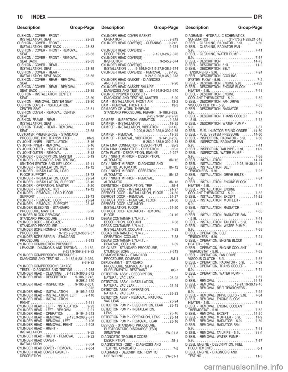
CUSHION / COVER - FRONT -
INSTALLATION, SEAT.................23-83
CUSHION / COVER - FRONT -
INSTALLATION, SEAT BACK............23-83
CUSHION / COVER - FRONT - REMOVAL,
SEAT ..............................23-83
CUSHION / COVER - FRONT - REMOVAL,
SEAT BACK.........................23-83
CUSHION / COVER - REAR -
INSTALLATION, SEAT.................23-85
CUSHION / COVER - REAR -
INSTALLATION, SEAT BACK............23-85
CUSHION / COVER - REAR - REMOVAL,
SEAT ..............................23-85
CUSHION / COVER - REAR - REMOVAL,
SEAT BACK.........................23-85
CUSHION - INSTALLATION, CENTER
SEAT ..............................23-80
CUSHION - REMOVAL, CENTER SEAT.....23-80
CUSHION COVER - INSTALLATION,
CENTER SEAT.......................23-81
CUSHION COVER - REMOVAL, CENTER
SEAT ..............................23-81
CUSHION FRAME - REAR -
INSTALLATION, SEAT.................23-85
CUSHION FRAME - REAR - REMOVAL,
SEAT ..............................23-85
CUSTOMER PREFERENCES - STANDARD
PROCEDURE, RKE TRANSMITTER........8N-9
CV JOINT-INNER - INSTALLATION........3-16
CV JOINT-INNER - REMOVAL............3-16
CV JOINT-OUTER - INSTALLATION........3-13
CV JOINT-OUTER - REMOVAL............3-13
CYLINDER - DESCRIPTION, MASTER......5-19
CYLINDER - DIAGNOSIS AND TESTING,
IGNITION SWITCH AND KEY LOCK.......19-11
CYLINDER - INSTALLATION, KEY........19-12
CYLINDER - INSTALLATION, LOAD
FLOOR SUPPORT....................23-73
CYLINDER - INSTALLATION, LOCK.......23-24
CYLINDER - INSTALLATION, SUPPORT....23-49
CYLINDER - OPERATION, MASTER........5-20
CYLINDER - REMOVAL, KEY............19-12
CYLINDER - REMOVAL, LOAD FLOOR
SUPPORT..........................23-73
CYLINDER - REMOVAL, LOCK...........23-24
CYLINDER - REMOVAL, SUPPORT.......23-48
CYLINDER BLEEDING - STANDARD
PROCEDURE, MASTER.................5-20
CYLINDER BLOCK REFACING -
STANDARD PROCEDURE...............9-312
CYLINDER BORE - DE-GLAZE -
STANDARD PROCEDURE...............9-313
CYLINDER BORE HONING - STANDARD
PROCEDURE..........9-126,9-233,9-360,9-37
CYLINDER BORE REPAIR - STANDARD
PROCEDURE........................9-313
CYLINDER COMBUSTION PRESSURE
LEAKAGE - DIAGNOSIS AND TESTING....9-182,
9-231,9-359,9-8,9-92
CYLINDER COMPRESSION PRESSURE -
DIAGNOSIS AND TESTING . . . 9-182,9-231,9-359,
9-8,9-92
CYLINDER COMPRESSION/LEAKAGE
TESTS - DIAGNOSIS AND TESTING......9-288
CYLINDER HEAD - CLEANING . 9-195,9-300,9-372
CYLINDER HEAD - DESCRIPTION . . 9-106,9-243,
9-298,9-370
CYLINDER HEAD - INSPECTION....9-195,9-301,
9-372
CYLINDER HEAD - INSTALLATION . . 9-195,9-372
CYLINDER HEAD - INSTALLATION, LEFT . . 9-110
CYLINDER HEAD - INSTALLATION,
RIGHT.............................9-111
CYLINDER HEAD - LEFT - INSTALLATION . . . 9-23
CYLINDER HEAD - LEFT - REMOVAL......9-21
CYLINDER HEAD - OPERATION.....9-194,9-243
CYLINDER HEAD - REMOVAL . 9-195,9-298,9-371
CYLINDER HEAD - REMOVAL, LEFT......9-106
CYLINDER HEAD - REMOVAL, RIGHT.....9-108
CYLINDER HEAD - RIGHT -
INSTALLATION
........................9-32
CYLINDER HEAD - RIGHT - REMOVAL
.....9-32
CYLINDER HEAD COVER -
INSTALLATION
.......................9-304
CYLINDER HEAD COVER - REMOVAL
.....9-304
CYLINDER HEAD COVER GASKET -
DESCRIPTION
.......................9-243CYLINDER HEAD COVER GASKET -
OPERATION.........................9-243
CYLINDER HEAD COVER(S) - CLEANING . . 9-245,
9-374
CYLINDER HEAD COVER(S) -
DESCRIPTION..............9-121,9-26,9-373
CYLINDER HEAD COVER(S) -
INSPECTION...................9-245,9-374
CYLINDER HEAD COVER(S) -
INSTALLATION....9-196,9-245,9-27,9-36,9-374
CYLINDER HEAD COVER(S) - REMOVAL . . 9-196,
9-245,9-26,9-35,9-373
CYLINDER HEAD GASKET - DIAGNOSIS
AND TESTING........................9-20
CYLINDER HEAD GASKET FAILURE -
DIAGNOSIS AND TESTING . . . 9-194,9-243,9-370
CYLINDER/POWER BOOSTER -
DIAGNOSIS AND TESTING, MASTER......5-20
DAM - INSTALLATION, FRONT AIR........13-2
DAM - REMOVAL, FRONT AIR...........13-2
DAMAGED OR WORN THREADS -
STANDARD PROCEDURE, REPAIR . . 9-186,9-232,
9-289,9-361,9-9,9-93
DAMPER - INSPECTION, VIBRATION.....9-335
DAMPER - INSTALLATION..............19-35
DAMPER - INSTALLATION, VIBRATION . . . 9-142,
9-209,9-263,9-335,9-392,9-55
DAMPER - REMOVAL.................19-35
DAMPER - REMOVAL, VIBRATION . . 9-141,9-209,
9-263,9-335,9-392,9-54
DATA LINK CONNECTOR - DESCRIPTION . . . 8E-3
DATA LINK CONNECTOR - OPERATION......8E-3
DATA PLATE - DESCRIPTION, ENGINE....9-297
DAY / NIGHT MIRROR - DESCRIPTION,
AUTOMATIC........................8N-12
DAY / NIGHT MIRROR - DIAGNOSIS AND
TESTING, AUTOMATIC................8N-12
DAY / NIGHT MIRROR - OPERATION,
AUTOMATIC........................8N-12
DAY / NIGHT MIRROR - REMOVAL,
AUTOMATIC........................8N-13
DEFINITION - DESCRIPTION, TRIP........25-4
DEFROST DOOR - INSTALLATION........24-27
DEFROST DOOR - INSTALLATION, FLOOR . 24-30
DEFROST DOOR - REMOVAL...........24-27
DEFROST DOOR - REMOVAL, FLOOR.....24-30
DEFROST DOOR ACTUATOR -
INSTALLATION, FLOOR................24-20
DEFROST DOOR ACTUATOR - REMOVAL,
FLOOR.............................24-19
DEGAS CONTAINER-3.7L/4.7L -
DESCRIPTION, COOLANT...............7-38
DEGAS CONTAINER-3.7L/4.7L -
INSTALLATION, COOLANT...............7-39
DEGAS CONTAINER-3.7L/4.7L -
OPERATION, COOLANT.................7-38
DEGAS CONTAINER-3.7L/4.7L -
REMOVAL, COOLANT..................7-39
DE-GLAZE - STANDARD PROCEDURE,
CYLINDER BORE.....................9-313
DEMAGNETIZING - STANDARD
PROCEDURE, COMPASS...............8M-4
DEPLOYMENT - STANDARD
PROCEDURE, SERVICE AFTER A
SUPPLEMENTAL RESTRAINT
............8O-7
DETECTION ASSY - DESCRIPTION,
NATURAL VAC LEAK
..................25-23
DETECTION ASSY - INSTALLATION,
NATURAL VAC LEAK
..................25-24
DETECTION ASSY - OPERATION,
NATURAL VAC LEAK
..................25-23
DETECTION ASSY - REMOVAL, NATURAL
VAC LEAK
..........................25-24
DETECTION PUMP - DESCRIPTION, LEAK
. 25-13
DETECTION PUMP - INSTALLATION,
LEAK
..............................25-16
DETECTION PUMP - OPERATION, LEAK
. . . 25-14
DETECTION PUMP - REMOVAL, LEAK
....25-16
DEVICES - STANDARD PROCEDURE,
ELECTROSTATIC DISCHARGE (ESD)
SENSITIVE
........................8W-01-8
DIAGNOSTIC TROUBLE CODES -
DESCRIPTION
........................25-1
DIAGNOSTICS (OBD) - DIAGNOSIS AND
TESTING, ON-BOARD
...................7-5
DIAGRAMS - DESCRIPTION, HOW TO
USE WIRING
......................8W-01-1DIAGRAMS - HYDRAULIC SCHEMATICS,
SCHEMATICS...........21-175,21-355,21-513
DIESEL - CLEANING, RADIATOR - 5.9L....7-60
DIESEL - CLEANING, RADIATOR FAN -
5.9L................................7-41
DIESEL - CLEANING, WATER PUMP -
5.9L................................7-67
DIESEL - DESCRIPTION...............14-73
DIESEL - DESCRIPTION, 5.9L............11-2
DIESEL - DESCRIPTION, BELT
TENSIONERS - 5.9L...................7-24
DIESEL - DESCRIPTION, COOLING
SYSTEM FLOW - 5.9L...................7-2
DIESEL - DESCRIPTION, ENGINE 5.9L....9-282
DIESEL - DESCRIPTION, ENGINE BLOCK
HEATER - 5.9L........................7-43
DIESEL - DESCRIPTION, ENGINE
COOLANT THERMOSTAT - 5.9L...........7-52
DIESEL - DESCRIPTION, FAN DRIVE
VISCOUS CLUTCH - 5.9L...............7-55
DIESEL - DESCRIPTION, RADIATOR -
5.9L................................7-59
DIESEL - DESCRIPTION, TRANS COOLER
- 5.9L..............................7-73
DIESEL - DESCRIPTION, WATER PUMP -
5.9L................................7-67
DIESEL - FUEL INJECTOR FIRING ORDER . 14-60
DIESEL - FUEL SYSTEM PRESSURE......14-60
DIESEL - INSPECTION, RADIATOR - 5.9L . . . 7-60
DIESEL - INSPECTION, RADIATOR FAN -
5.9L................................7-41
DIESEL - INSPECTION, TAILPIPE - 5.9L....11-9
DIESEL - INSPECTION, WATER PUMP -
5.9L................................7-68
DIESEL - INSTALLATION...............14-74
DIESEL - INSTALLATION.....19-25,19-30,19-41
DIESEL - INSTALLATION, BELT
TENSIONERS - 5.9L...................7-25
DIESEL - INSTALLATION, DRIVE BELTS -
5.9L................................7-34
DIESEL - INSTALLATION, ENGINE BLOCK
HEATER - 5.9L........................7-44
DIESEL - INSTALLATION, ENGINE
COOLANT THERMOSTAT - 5.9L...........7-53
DIESEL - INSTALLATION, EXCEPT........14-22
DIESEL - INSTALLATION, MUFFLER -
5.9L................................11-9
DIESEL - INSTALLATION, RADIATOR -
5.9L................................7-60
DIESEL - INSTALLATION, RADIATOR FAN
- 5.9L..............................7-41
DIESEL - INSTALLATION, TAILPIPE - 5.9L . . 11-9
DIESEL - INSTALLATION, WATER PUMP -
5.9L................................7-68
DIESEL - OPERATION, BELT
TENSIONERS - 5.9L...................7-24
DIESEL - OPERATION, ENGINE BLOCK
HEATER - 5.9L........................7-43
DIESEL - OPERATION, ENGINE COOLANT
THERMOSTAT - 5.9L...................7-52
DIESEL - OPERATION, FAN DRIVE
VISCOUS CLUTCH - 5.9L...............7-55
DIESEL - OPERATION, RADIATOR - 5.9L . . . 7-59
DIESEL - OPERATION, TRANS COOLER -
5.9L................................7-74
DIESEL - OPERATION, WATER PUMP -
5.9L................................7-67
DIESEL - REMOVAL...................14-73
DIESEL - REMOVAL.........19-24,19-30,19-40
DIESEL - REMOVAL, BELT TENSIONERS -
5.9L................................7-25
DIESEL - REMOVAL, DRIVE BELTS - 5.9L . . 7-34
DIESEL - REMOVAL, ENGINE BLOCK
HEATER - 5.9L........................7-43
DIESEL - REMOVAL, ENGINE COOLANT
THERMOSTAT - 5.9L...................7-53
DIESEL - REMOVAL, EXCEPT...........14-20
DIESEL - REMOVAL, MUFFLER - 5.9L.....11-9
DIESEL - REMOVAL, RADIATOR - 5.9L.....7-59
DIESEL - REMOVAL, RADIATOR FAN -
5.9L
................................7-41
DIESEL - REMOVAL, TAILPIPE - 5.9L
......11-9
DIESEL - REMOVAL, WATER PUMP -
5.9L
................................7-67
DIESEL ENGINE - DESCRIPTION, FUEL
REQUIREMENTS
.......................0-1
DIESEL ENGINE - DIAGNOSIS AND
TESTING
............................11-3
10 INDEXDR
Description Group-Page Description Group-Page Description Group-Page