battery DODGE RAM 2003 Service Repair Manual
[x] Cancel search | Manufacturer: DODGE, Model Year: 2003, Model line: RAM, Model: DODGE RAM 2003Pages: 2895, PDF Size: 83.15 MB
Page 7 of 2895
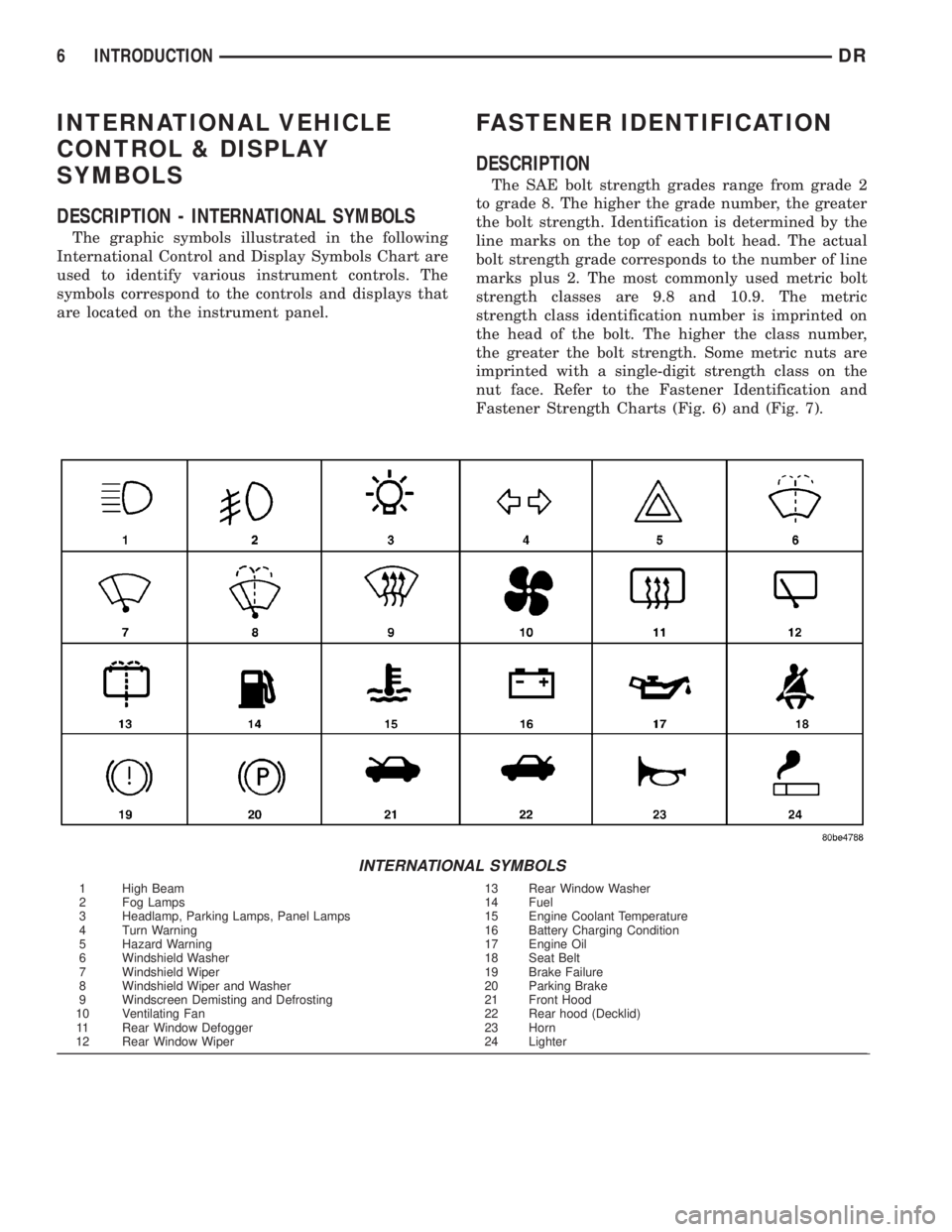
INTERNATIONAL VEHICLE
CONTROL & DISPLAY
SYMBOLS
DESCRIPTION - INTERNATIONAL SYMBOLS
The graphic symbols illustrated in the following
International Control and Display Symbols Chart are
used to identify various instrument controls. The
symbols correspond to the controls and displays that
are located on the instrument panel.
FASTENER IDENTIFICATION
DESCRIPTION
The SAE bolt strength grades range from grade 2
to grade 8. The higher the grade number, the greater
the bolt strength. Identification is determined by the
line marks on the top of each bolt head. The actual
bolt strength grade corresponds to the number of line
marks plus 2. The most commonly used metric bolt
strength classes are 9.8 and 10.9. The metric
strength class identification number is imprinted on
the head of the bolt. The higher the class number,
the greater the bolt strength. Some metric nuts are
imprinted with a single-digit strength class on the
nut face. Refer to the Fastener Identification and
Fastener Strength Charts (Fig. 6) and (Fig. 7).
INTERNATIONAL SYMBOLS
1 High Beam 13 Rear Window Washer
2 Fog Lamps 14 Fuel
3 Headlamp, Parking Lamps, Panel Lamps 15 Engine Coolant Temperature
4 Turn Warning 16 Battery Charging Condition
5 Hazard Warning 17 Engine Oil
6 Windshield Washer 18 Seat Belt
7 Windshield Wiper 19 Brake Failure
8 Windshield Wiper and Washer 20 Parking Brake
9 Windscreen Demisting and Defrosting 21 Front Hood
10 Ventilating Fan 22 Rear hood (Decklid)
11 Rear Window Defogger 23 Horn
12 Rear Window Wiper 24 Lighter
6 INTRODUCTIONDR
Page 19 of 2895
MAINTENANCE SCHEDULES
DESCRIPTION
Maintenance Schedule Information not included in
this section, is located in the appropriate Owner's
Manual.
There are two maintenance schedules that show
therequiredservice for your vehicle.
First is ScheduleªBº. It is for vehicles that are
operated under the conditions that are listed below
and at the beginning of the schedule.
²Day or night temperatures are below 0É C (32É
F).
²Stop and go driving.
²Extensive engine idling.
²Driving in dusty conditions.
²Short trips of less than 16 km (10 miles).
²More than 50% of your driving is at sustained
high speeds during hot weather, above 32É C (90É F).
²Trailer towing.
²Taxi, police, or delivery service (commercial ser-
vice).
²Off-road or desert operation.
²If equipped for and operating with E-85
(ethanol) fuel.
NOTE: Most vehicles are operated under the condi-
tions listed for Schedule(B(.
Second is ScheduleªAº. It is for vehicles that are
not operated under any of the conditions listed under
Schedule9B9.
Use the schedule that best describes your driving
conditions. Where time and mileage are listed, follow
the interval that occurs first.
CAUTION: Failure to perform the required mainte-
nance items may result in damage to the vehicle.
At Each Stop for Fuel
²Check the engine oil level about 5 minutes after
a fully warmed engine is shut off. Checking the oil
level while the vehicle is on level ground will
improve the accuracy of the oil level reading. Add oil
only when the level is at or below the ADD or MIN
mark.
²Check the windshield washer solvent and add if
required.
Once a Month
²Check tire pressure and look for unusual wear
or damage.
²Inspect the battery and clean and tighten the
terminals as required.
²Check the fluid levels of coolant reservoir, brake
master cylinder, power steering and transmission
and add as needed.
²Check all lights and all other electrical items for
correct operation.
At Each Oil Change
²Change the engine oil filter.
²Inspect the exhaust system.
²Inspect the brake hoses.
²Inspect the CV joints (if equipped) and front sus-
pension components.
²Check the automatic transmission fluid level.
²Check the manual transmission fluid level.
²Check the coolant level, hoses, and clamps.
²Rotate the tires at each oil change interval
shown on Schedule ªAº 10 000 km (6,000 miles) or
every other interval shown on Schedule ªBº 10 000
km (6,000 miles).
Schedule ªBº
Follow schedule ªBº if you usually operate your
vehicle under one or more of the following conditions.
²Day or night temperatures are below 0É C (32É
F).
²Stop and go driving.
²Extensive engine idling.
²Driving in dusty conditions.
²Short trips of less than 16 km (10 miles).
²More than 50% of your driving is at sustained
high speeds during hot weather, above 32É C (90É F).
²Trailer towing.
²Taxi, police, or delivery service (commercial ser-
vice).
²Off-road or desert operation.
²If equipped for and operating with E-85
(ethanol) fuel.
0 - 6 LUBRICATION & MAINTENANCEDR
Page 26 of 2895
JUMP STARTING
STANDARD PROCEDURE - JUMP STARTING
WARNING: REVIEW ALL SAFETY PRECAUTIONS
AND WARNINGS IN THE BATTERY SYSTEM SEC-
TION OF THE SERVICE MANUAL. (Refer to 8 -
ELECTRICAL/BATTERY SYSTEM/BATTERY - STAN-
DARD PROCEDURE)
²DO NOT JUMP START A FROZEN BATTERY,
PERSONAL INJURY CAN RESULT.
²IF EQUIPPED, DO NOT JUMP START WHEN
MAINTENANCE FREE BATTERY INDICATOR DOT IS
YELLOW OR BRIGHT COLOR.
²DO NOT JUMP START A VEHICLE WHEN THE
BATTERY FLUID IS BELOW THE TOP OF LEAD
PLATES.
²DO NOT ALLOW JUMPER CABLE CLAMPS TO
TOUCH EACH OTHER WHEN CONNECTED TO A
BOOSTER SOURCE.
²DO NOT USE OPEN FLAME NEAR BATTERY.
²REMOVE METALLIC JEWELRY WORN ON
HANDS OR WRISTS TO AVOID INJURY BY ACCI-
DENTAL ARCING OF BATTERY CURRENT.
²WHEN USING A HIGH OUTPUT BOOSTING
DEVICE, DO NOT ALLOW BATTERY VOLTAGE TO
EXCEED 16 VOLTS. REFER TO INSTRUCTIONS
PROVIDED WITH DEVICE BEING USED.
FAILURE TO FOLLOW THESE INSTRUCTIONS MAY
RESULT IN PERSONAL INJURY.
CAUTION: When using another vehicle as a
booster, do not allow vehicles to touch. Electrical
systems can be damaged on either vehicle.
TO JUMP START A DISABLED VEHICLE:
(1) Raise hood on disabled vehicle and visually
inspect engine compartment for:
²Battery cable clamp condition, clean if necessary.
²Frozen battery.
²Yellow or bright color test indicator, if equipped.
²Low battery fluid level.
²Generator drive belt condition and tension.
²Fuel fumes or leakage, correct if necessary.CAUTION: If the cause of starting problem on dis-
abled vehicle is severe, damage to booster vehicle
charging system can result.
(2) When using another vehicle as a booster
source, park the booster vehicle within cable reach.
Turn off all accessories, set the parking brake, place
the automatic transmission in PARK or the manual
transmission in NEUTRAL and turn the ignition
OFF.
(3) On disabled vehicle, place gear selector in park
or neutral and set park brake. Turn off all accesso-
ries.
(4) Connect jumper cables to booster battery. RED
clamp to positive terminal (+). BLACK clamp to neg-
ative terminal (-). DO NOT allow clamps at opposite
end of cables to touch, electrical arc will result.
Review all warnings in this procedure.
(5) On disabled vehicle, connect RED jumper cable
clamp to positive (+) terminal. Connect BLACK
jumper cable clamp to engine ground as close to the
ground cable attaching point as possible.
(6) Start the engine in the vehicle which has the
booster battery, let the engine idle a few minutes,
then start the engine in the vehicle with the dis-
charged battery.
CAUTION: Do not crank starter motor on disabled
vehicle for more than 15 seconds, starter will over-
heat and could fail.
(7) Allow battery in disabled vehicle to charge to
at least 12.4 volts (75% charge) before attempting to
start engine. If engine does not start within 15 sec-
onds, stop cranking engine and allow starter to cool
(15 min.), before cranking again.
DISCONNECT CABLE CLAMPS AS FOLLOWS:
²Disconnect BLACK cable clamp from engine
ground on disabled vehicle.
²When using a Booster vehicle, disconnect
BLACK cable clamp from battery negative terminal.
Disconnect RED cable clamp from battery positive
terminal.
²Disconnect RED cable clamp from battery posi-
tive terminal on disabled vehicle.
DRLUBRICATION & MAINTENANCE 0 - 13
Page 84 of 2895
HALF SHAFT
TABLE OF CONTENTS
page page
HALF SHAFT
CAUTION.............................11
DIAGNOSIS AND TESTING................11
REMOVAL.............................11
INSTALLATION.........................12
SPECIFICATIONS.......................12
SPECIAL TOOLS.......................12CV JOINT-OUTER
REMOVAL.............................13
INSTALLATION.........................13
CV JOINT-INNER
REMOVAL.............................16
INSTALLATION.........................16
HALF SHAFT
CAUTION
CAUTION:: Never grasp half shaft assembly by the
boots. This may cause the boot to pucker or crease
and reduce the service life of the boot.
Avoid over angulating or stroking the C/V joints
when handling the half shaft.
Half shafts exposed to battery acid, transmission
fluid, brake fluid, differential fluid or gasoline may
cause the boots to deteriorate.
DIAGNOSIS AND TESTING
Check for grease at the inboard and outboard C/V
joint. This is a sign of boot or boot clamp damage.
NOISE/VIBRATION IN TURNS
A clicking noise or a vibration in turns could be
caused by a damaged outer C/V or inner tripod joint
seal boot or seal boot clamps. This will result in the
loss/contamination of the joint grease, resulting in
inadequate lubrication of the joint. Noise could also
be caused by another component of the vehicle com-
ing in contact with the half shafts.
CLUNKING NOISE DURING ACCELERATION
This noise may be a result of a damaged or worn
C/V joint. A torn boot or loose/missing clamp on the
inner/outer joint which has allowed the grease to be
lost will damage the C/V joint.
SHUDDER/VIBRATION DURING ACCELERATION
This problem could be a result of a worn/damaged
inner tripod joint or a sticking tripod joint. Improper
wheel alignment may also cause a shudder or vibra-
tion.
VIBRATION AT HIGHWAY SPEEDS
This problem could be a result of out of balance
front tires or tire/wheel runout. Foreign material
(mud, etc.) packed on the backside of the wheel(s)
will also cause a vibration.
REMOVAL
(1) Loosen lug nuts and hub nut while the with
the vehicle brakes applied.
(2) Raise and support the vehicle.
(3) Remove wheel and tire assembly
(4) Remove half shaft hub nut.
(5) Remove brake caliper and rotor.
(6) Position hydraulic jack under lower suspension
arm and raise jack to unload rebound bumper.
(7) Remove lower shock absorber bolt.
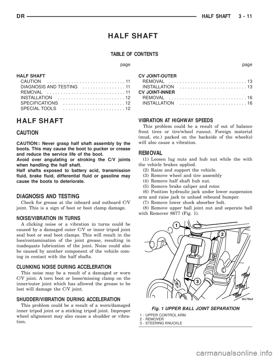
(8) Remove upper ball joint nut and seperate ball
with Remover 8677 (Fig. 1).
Fig. 1 UPPER BALL JOINT SEPARATION
1 - UPPER CONTROL ARM
2 - REMOVER
3 - STEERING KNUCKLE
DRHALF SHAFT 3 - 11
Page 250 of 2895
REMOVAL
NOTE: The brake pedal is serviced as a complete
assembly including accelerator pedal and the
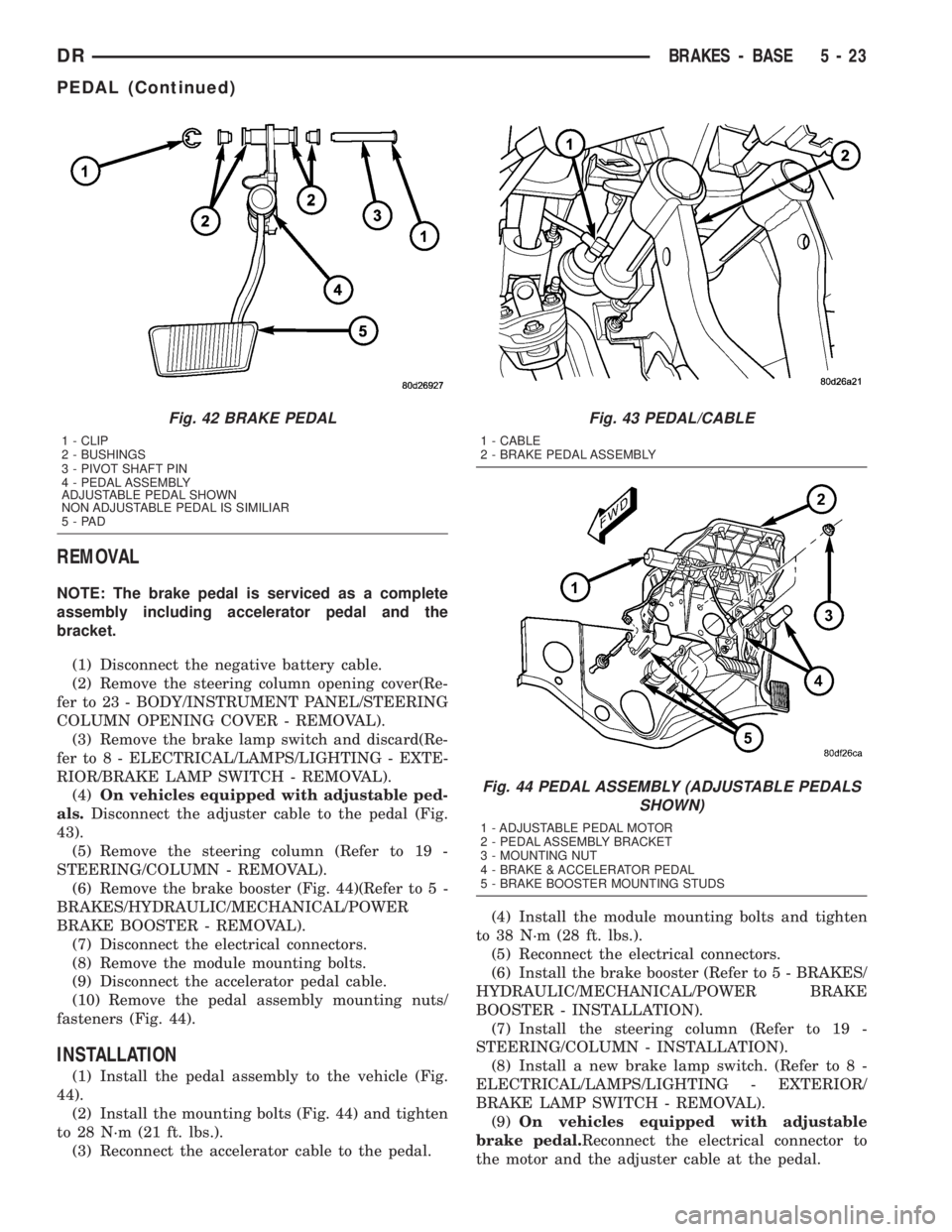
bracket.
(1) Disconnect the negative battery cable.
(2) Remove the steering column opening cover(Re-
fer to 23 - BODY/INSTRUMENT PANEL/STEERING
COLUMN OPENING COVER - REMOVAL).
(3) Remove the brake lamp switch and discard(Re-
fer to 8 - ELECTRICAL/LAMPS/LIGHTING - EXTE-
RIOR/BRAKE LAMP SWITCH - REMOVAL).
(4)On vehicles equipped with adjustable ped-
als.Disconnect the adjuster cable to the pedal (Fig.
43).
(5) Remove the steering column (Refer to 19 -
STEERING/COLUMN - REMOVAL).
(6) Remove the brake booster (Fig. 44)(Refer to 5 -
BRAKES/HYDRAULIC/MECHANICAL/POWER
BRAKE BOOSTER - REMOVAL).
(7) Disconnect the electrical connectors.
(8) Remove the module mounting bolts.
(9) Disconnect the accelerator pedal cable.
(10) Remove the pedal assembly mounting nuts/
fasteners (Fig. 44).
INSTALLATION
(1) Install the pedal assembly to the vehicle (Fig.
44).
(2) Install the mounting bolts (Fig. 44) and tighten
to 28 N´m (21 ft. lbs.).
(3) Reconnect the accelerator cable to the pedal.(4) Install the module mounting bolts and tighten
to 38 N´m (28 ft. lbs.).
(5) Reconnect the electrical connectors.
(6) Install the brake booster (Refer to 5 - BRAKES/
HYDRAULIC/MECHANICAL/POWER BRAKE
BOOSTER - INSTALLATION).
(7) Install the steering column (Refer to 19 -
STEERING/COLUMN - INSTALLATION).
(8) Install a new brake lamp switch. (Refer to 8 -
ELECTRICAL/LAMPS/LIGHTING - EXTERIOR/
BRAKE LAMP SWITCH - REMOVAL).
(9)On vehicles equipped with adjustable
brake pedal.Reconnect the electrical connector to
the motor and the adjuster cable at the pedal.
Fig. 42 BRAKE PEDAL
1 - CLIP
2 - BUSHINGS
3 - PIVOT SHAFT PIN
4 - PEDAL ASSEMBLY
ADJUSTABLE PEDAL SHOWN
NON ADJUSTABLE PEDAL IS SIMILIAR
5-PAD
Fig. 43 PEDAL/CABLE
1 - CABLE
2 - BRAKE PEDAL ASSEMBLY
Fig. 44 PEDAL ASSEMBLY (ADJUSTABLE PEDALS
SHOWN)
1 - ADJUSTABLE PEDAL MOTOR
2 - PEDAL ASSEMBLY BRACKET
3 - MOUNTING NUT
4 - BRAKE & ACCELERATOR PEDAL
5 - BRAKE BOOSTER MOUNTING STUDS
DRBRAKES - BASE 5 - 23
PEDAL (Continued)
Page 251 of 2895
(10) Install the steering column opening cover
(Refer to 23 - BODY/INSTRUMENT PANEL/STEER-
ING COLUMN OPENING COVER - INSTALLA-
TION).
(11) Reconnect the negative battery cable.
ADJUSTABLE PEDAL MOTOR
DESCRIPTION
The Adjustable Pedals System (APS) is designed to
enable the fore and aft repositioning of the brake and
accelerator pedals. This results in improved ergonom-
ics in relation to the steering wheel for taller and
shorter drivers. Being able to adjust the pedal posi-
tions also allows the driver to set steering wheel tilt
and seat position to the most comfortable position.
The position of the brake and accelerator pedals can
be adjusted without compromising safety or comfort
in actuating the pedals.
Change of pedal position is accomplished by means
of a motor driven screw. Operating the adjustable
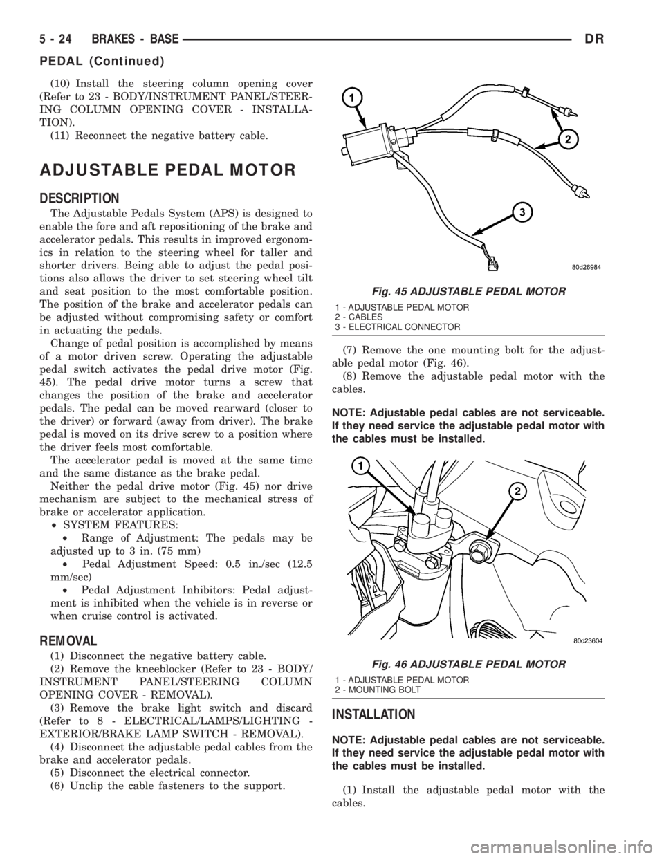
pedal switch activates the pedal drive motor (Fig.
45). The pedal drive motor turns a screw that
changes the position of the brake and accelerator
pedals. The pedal can be moved rearward (closer to
the driver) or forward (away from driver). The brake
pedal is moved on its drive screw to a position where
the driver feels most comfortable.
The accelerator pedal is moved at the same time
and the same distance as the brake pedal.
Neither the pedal drive motor (Fig. 45) nor drive
mechanism are subject to the mechanical stress of
brake or accelerator application.
²SYSTEM FEATURES:
²Range of Adjustment: The pedals may be
adjusted up to 3 in. (75 mm)
²Pedal Adjustment Speed: 0.5 in./sec (12.5
mm/sec)
²Pedal Adjustment Inhibitors: Pedal adjust-
ment is inhibited when the vehicle is in reverse or
when cruise control is activated.
REMOVAL
(1) Disconnect the negative battery cable.
(2) Remove the kneeblocker (Refer to 23 - BODY/
INSTRUMENT PANEL/STEERING COLUMN
OPENING COVER - REMOVAL).
(3) Remove the brake light switch and discard
(Refer to 8 - ELECTRICAL/LAMPS/LIGHTING -
EXTERIOR/BRAKE LAMP SWITCH - REMOVAL).
(4) Disconnect the adjustable pedal cables from the
brake and accelerator pedals.
(5) Disconnect the electrical connector.
(6) Unclip the cable fasteners to the support.(7) Remove the one mounting bolt for the adjust-
able pedal motor (Fig. 46).
(8) Remove the adjustable pedal motor with the
cables.
NOTE: Adjustable pedal cables are not serviceable.
If they need service the adjustable pedal motor with
the cables must be installed.
INSTALLATION
NOTE: Adjustable pedal cables are not serviceable.
If they need service the adjustable pedal motor with
the cables must be installed.
(1) Install the adjustable pedal motor with the
cables.
Fig. 45 ADJUSTABLE PEDAL MOTOR
1 - ADJUSTABLE PEDAL MOTOR
2 - CABLES
3 - ELECTRICAL CONNECTOR
Fig. 46 ADJUSTABLE PEDAL MOTOR
1 - ADJUSTABLE PEDAL MOTOR
2 - MOUNTING BOLT
5 - 24 BRAKES - BASEDR
PEDAL (Continued)
Page 252 of 2895
(2) Install the one mounting bolt for the adjustable
pedal motor (Fig. 46).
(3) Clip the cable fasteners to the support.
(4) Reconnect the electrical connector.
(5) Reconnect the adjustable pedal cables to the
brake and accelerator pedals.
(6) Install the new brake light switch (Refer to 8 -
ELECTRICAL/LAMPS/LIGHTING - EXTERIOR/
BRAKE LAMP SWITCH - REMOVAL).
(7) Install the kneeblocker (Refer to 23 - BODY/IN-
STRUMENT PANEL/STEERING COLUMN OPEN-
ING COVER - INSTALLATION).
(8) Reconnect the negative battery cable.
(9) Check for proper operation of the pedals.
POWER BRAKE BOOSTER
DESCRIPTION
All models use a tandem diaphragm, power brake
booster.
NOTE: The power brake booster is not a repairable
component. The booster must be replaced as an
assembly if diagnosis indicates a malfunction has
occurred.
OPERATION
The booster unit consists of a single housing
divided into two by a tandem diaphragm. The outer
edge of the diaphragm is secured to the housing. The
booster push rod, which connects the booster to the
brake pedal and master cylinder, is attached to the
center of the diaphragm. A check valve is used in the
booster outlet connected to the engine intake mani-
fold. Power assist is generated by utilizing a combi-
nation of vacuum and atmospheric pressure to boost
brake assist.
REMOVAL
(1) Remove master cylinder. (Refer to 5 - BRAKES/
HYDRAULIC/MECHANICAL/MASTER CYLINDER -
REMOVAL).
(2) Disconnect vacuum line at booster.
(3) Remove clip securing booster push rod to brake
pedal (Refer to 5 - BRAKES/HYDRAULIC/MECHAN-
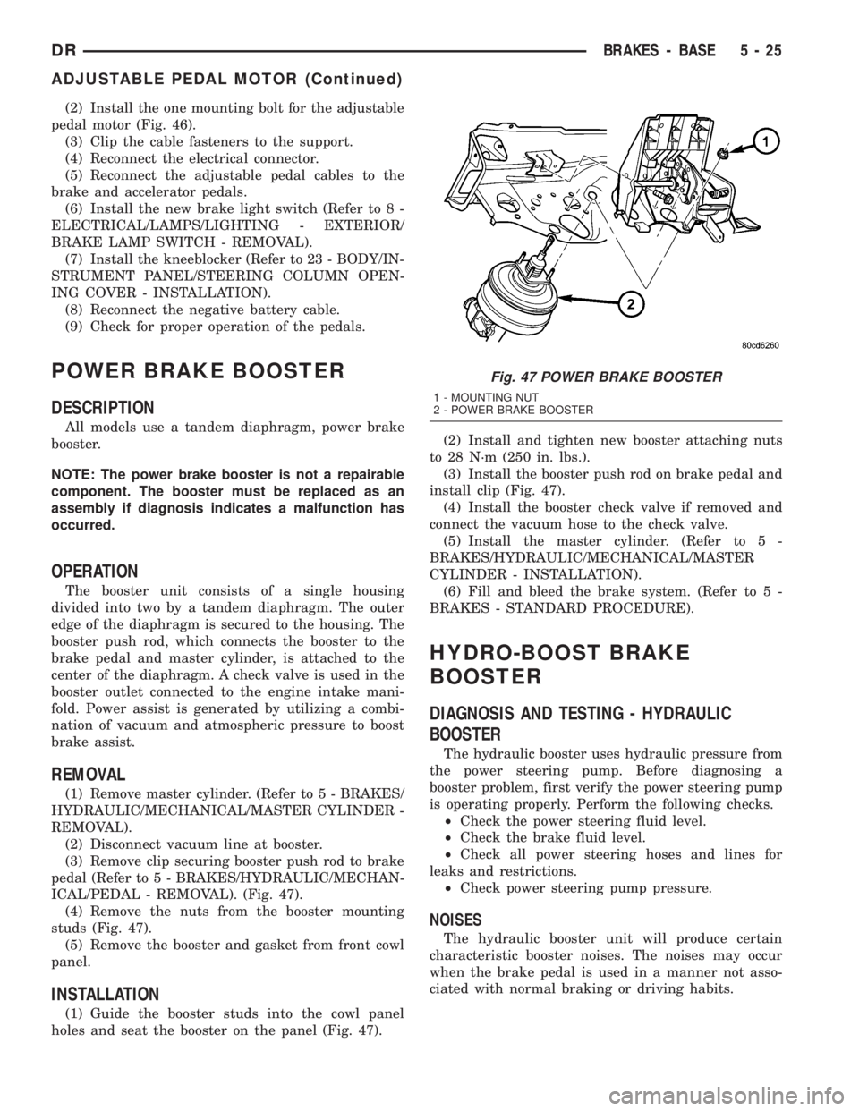
ICAL/PEDAL - REMOVAL). (Fig. 47).
(4) Remove the nuts from the booster mounting
studs (Fig. 47).
(5) Remove the booster and gasket from front cowl
panel.
INSTALLATION
(1) Guide the booster studs into the cowl panel
holes and seat the booster on the panel (Fig. 47).(2) Install and tighten new booster attaching nuts
to 28 N´m (250 in. lbs.).
(3) Install the booster push rod on brake pedal and
install clip (Fig. 47).
(4) Install the booster check valve if removed and
connect the vacuum hose to the check valve.
(5) Install the master cylinder. (Refer to 5 -
BRAKES/HYDRAULIC/MECHANICAL/MASTER
CYLINDER - INSTALLATION).
(6) Fill and bleed the brake system. (Refer to 5 -
BRAKES - STANDARD PROCEDURE).
HYDRO-BOOST BRAKE
BOOSTER
DIAGNOSIS AND TESTING - HYDRAULIC
BOOSTER
The hydraulic booster uses hydraulic pressure from
the power steering pump. Before diagnosing a
booster problem, first verify the power steering pump
is operating properly. Perform the following checks.
²Check the power steering fluid level.
²Check the brake fluid level.
²Check all power steering hoses and lines for
leaks and restrictions.
²Check power steering pump pressure.
NOISES
The hydraulic booster unit will produce certain
characteristic booster noises. The noises may occur
when the brake pedal is used in a manner not asso-
ciated with normal braking or driving habits.
Fig. 47 POWER BRAKE BOOSTER
1 - MOUNTING NUT
2 - POWER BRAKE BOOSTER
DRBRAKES - BASE 5 - 25
ADJUSTABLE PEDAL MOTOR (Continued)
Page 265 of 2895
RELEASE HANDLE
REMOVAL
(1) Disconnect and isolate the battery negative
cable.
(2) Reach under the driver side outboard end of
the instrument panel to access and unsnap the plas-
tic retainer clip that secures the park brake release
linkage rod to the park brake mechanism on the left
cowl side inner panel.
(3) Disengage the park brake release linkage rod
end from the park brake mechanism.
(4) Lift the park brake release handle to access
and unsnap the plastic retainer clip that secures the
park brake release linkage rod to the lever on the
back of the park brake release handle.
(5) Lower the park brake release handle and reach
under the driver side outboard end of the instrument
panel to disengage the park brake release linkage
rod end from the lever on the back of the park brake
release handle.
(6) Lift the park brake release handle to access the
handle mounting bracket.
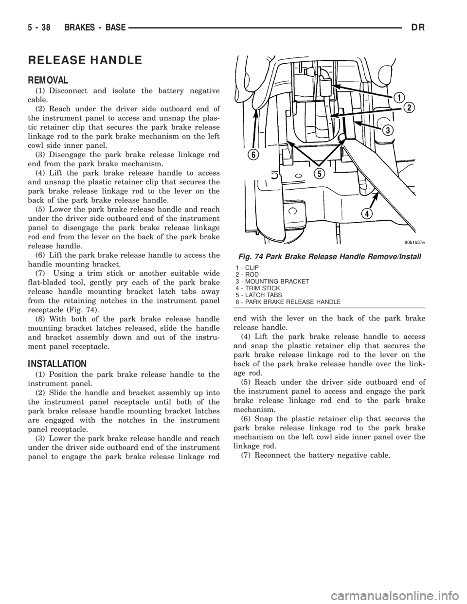
(7) Using a trim stick or another suitable wide
flat-bladed tool, gently pry each of the park brake
release handle mounting bracket latch tabs away
from the retaining notches in the instrument panel
receptacle (Fig. 74).
(8) With both of the park brake release handle
mounting bracket latches released, slide the handle
and bracket assembly down and out of the instru-
ment panel receptacle.
INSTALLATION
(1) Position the park brake release handle to the
instrument panel.
(2) Slide the handle and bracket assembly up into
the instrument panel receptacle until both of the
park brake release handle mounting bracket latches
are engaged with the notches in the instrument
panel receptacle.
(3) Lower the park brake release handle and reach
under the driver side outboard end of the instrument
panel to engage the park brake release linkage rodend with the lever on the back of the park brake
release handle.
(4) Lift the park brake release handle to access
and snap the plastic retainer clip that secures the
park brake release linkage rod to the lever on the
back of the park brake release handle over the link-
age rod.
(5) Reach under the driver side outboard end of
the instrument panel to access and engage the park
brake release linkage rod end to the park brake
mechanism.
(6) Snap the plastic retainer clip that secures the
park brake release linkage rod to the park brake
mechanism on the left cowl side inner panel over the
linkage rod.
(7) Reconnect the battery negative cable.
Fig. 74 Park Brake Release Handle Remove/Install
1 - CLIP
2 - ROD
3 - MOUNTING BRACKET
4 - TRIM STICK
5 - LATCH TABS
6 - PARK BRAKE RELEASE HANDLE
5 - 38 BRAKES - BASEDR
Page 266 of 2895
BRAKES - ABS
TABLE OF CONTENTS
page page
BRAKES - ABS
DESCRIPTION.........................39
OPERATION...........................39
STANDARD PROCEDURE - ABS BRAKE
BLEEDING...........................40
SPECIFICATIONS
TORQUE CHART......................40
FRONT WHEEL SPEED SENSOR
DESCRIPTION.........................41
OPERATION...........................41
REMOVAL.............................41
INSTALLATION.........................42
REAR WHEEL SPEED SENSOR
DIAGNOSIS AND TESTING - REAR WHEEL
ANTILOCK...........................42
REMOVAL.............................42
INSTALLATION.........................43
TONE WHEEL
DIAGNOSIS AND TESTING - REAR WHEEL
SPEED SENSOR......................43HYDRAULIC/MECHANICAL
DESCRIPTION - ELECTRONIC VARIABLE
BRAKE PROPORTIONING...............43
OPERATION - ELECTRONIC VARIABLE
BRAKE PROPORTIONING...............43
HCU (HYDRAULIC CONTROL UNIT)
DESCRIPTION.........................43
OPERATION...........................43
REMOVAL.............................44
INSTALLATION.........................44
R WA L VA LV E
DESCRIPTION.........................44
OPERATION...........................44
REMOVAL.............................45
INSTALLATION.........................45
BRAKES - ABS
DESCRIPTION
The antilock brake system (ABS) is an electroni-
cally operated, three channel brake control system.
The vehicle has Electronic Variable Brake Propor-
tioning (EVBP) designed into the system which elim-
inates the combination/proportioning valve.
The system is designed to prevent wheel lockup
and maintain steering control during braking. Pre-
venting lockup is accomplished by modulating fluid
pressure to the wheel brake units.
The hydraulic system is a three channel design.
The front wheel brakes are controlled individually
and the rear wheel brakes in tandem. The ABS elec-
trical system is separate from other electrical circuits
in the vehicle. A specially programmed controller
antilock brake unit operates the system components.
ABS system major components include:
²Controller Antilock Brakes (CAB)
²Hydraulic Control Unit (HCU)
²Wheel Speed Sensors (WSS)
²ABS Warning Light
OPERATION
Battery voltage is supplied to the CAB. The CAB
performs a system initialization procedure at start
up. A check of the ABS motor is performed at 15
miles per hour. Initialization consists of a static and
dynamic self check of system electrical components.
The static and dynamic checks occurs at ignition
start up. During the dynamic check, the CAB briefly
cycles solenoids to verify operation. An audible noise
may be heard during this self check. This noise
should be considered normal. The ABS motor and
pump are then checked at a speed of 15 mile per
hour.
If an ABS component exhibits a fault during ini-
tialization, the CAB illuminates the amber warning
light and registers a fault code in the microprocessor
memory.
The CAB monitors wheel speed sensor inputs con-
tinuously while the vehicle is in motion. However,
the CAB will not activate any ABS components as
long as sensor inputs indicate normal braking.
During normal braking, the master cylinder, power
booster and wheel brake units all function as they
would in a vehicle without ABS. The HCU compo-
nents are not activated.
DRBRAKES - ABS 5 - 39
Page 271 of 2895
then opens the outlet valve, which also opens the
return circuit to the accumulators. Fluid pressure is
allowed to bleed off (decrease) as needed to prevent
wheel lock.
Once the period of high wheel slip has ended, the
CAB closes the outlet valve and begins a pressure
increase or hold cycle as needed.
PRESSURE HOLD
Both solenoid valves are closed in the pressure
hold cycle but only the inlet valve is energized. Fluid
apply pressure in the control channel is maintained
at a constant rate. The CAB maintains the hold cycle
until sensor inputs indicate a pressure change is nec-
essary.
PRESSURE INCREASE
The inlet valve is open and the outlet valve is
closed during the pressure increase cycle. The pres-
sure increase cycle is used to reapply thew brakes.
This cycle controls re-application of fluid apply pres-
sure.
REMOVAL
(1) Install a prop rod on the brake pedal to keep
pressure on the brake system.
(2) Disconnect the battery cables from the battery.
(3) Remove the battery.
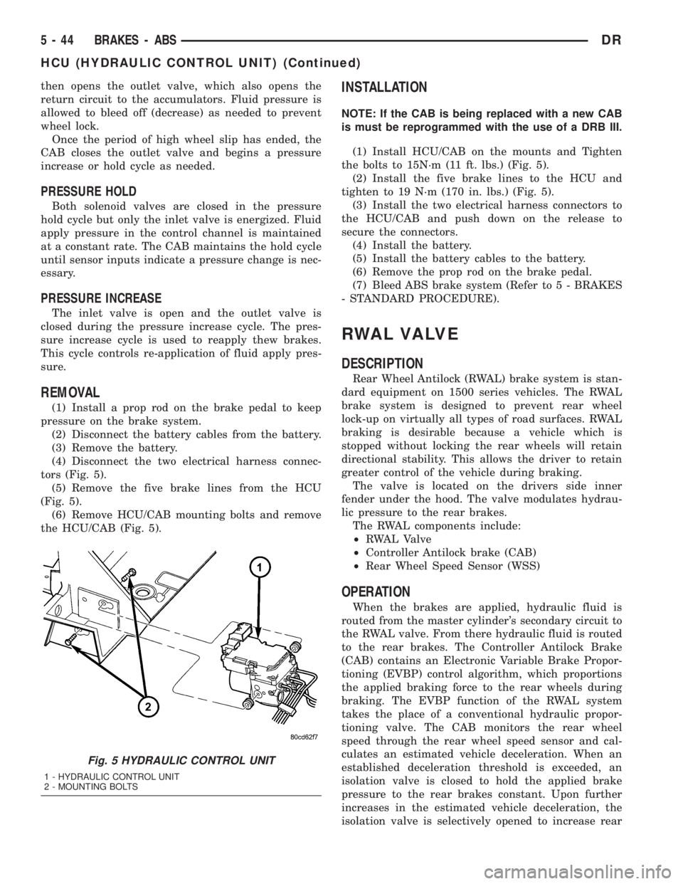
(4) Disconnect the two electrical harness connec-
tors (Fig. 5).
(5) Remove the five brake lines from the HCU
(Fig. 5).
(6) Remove HCU/CAB mounting bolts and remove
the HCU/CAB (Fig. 5).
INSTALLATION
NOTE: If the CAB is being replaced with a new CAB
is must be reprogrammed with the use of a DRB III.
(1) Install HCU/CAB on the mounts and Tighten
the bolts to 15N´m (11 ft. lbs.) (Fig. 5).
(2) Install the five brake lines to the HCU and
tighten to 19 N´m (170 in. lbs.) (Fig. 5).
(3) Install the two electrical harness connectors to
the HCU/CAB and push down on the release to
secure the connectors.
(4) Install the battery.
(5) Install the battery cables to the battery.
(6) Remove the prop rod on the brake pedal.
(7) Bleed ABS brake system (Refer to 5 - BRAKES
- STANDARD PROCEDURE).
RWAL VALVE
DESCRIPTION
Rear Wheel Antilock (RWAL) brake system is stan-
dard equipment on 1500 series vehicles. The RWAL
brake system is designed to prevent rear wheel
lock-up on virtually all types of road surfaces. RWAL
braking is desirable because a vehicle which is
stopped without locking the rear wheels will retain
directional stability. This allows the driver to retain
greater control of the vehicle during braking.
The valve is located on the drivers side inner
fender under the hood. The valve modulates hydrau-
lic pressure to the rear brakes.
The RWAL components include:
²RWAL Valve
²Controller Antilock brake (CAB)
²Rear Wheel Speed Sensor (WSS)
OPERATION
When the brakes are applied, hydraulic fluid is
routed from the master cylinder's secondary circuit to
the RWAL valve. From there hydraulic fluid is routed
to the rear brakes. The Controller Antilock Brake
(CAB) contains an Electronic Variable Brake Propor-
tioning (EVBP) control algorithm, which proportions
the applied braking force to the rear wheels during
braking. The EVBP function of the RWAL system
takes the place of a conventional hydraulic propor-
tioning valve. The CAB monitors the rear wheel
speed through the rear wheel speed sensor and cal-
culates an estimated vehicle deceleration. When an
established deceleration threshold is exceeded, an
isolation valve is closed to hold the applied brake
pressure to the rear brakes constant. Upon further
increases in the estimated vehicle deceleration, the
isolation valve is selectively opened to increase rear
Fig. 5 HYDRAULIC CONTROL UNIT
1 - HYDRAULIC CONTROL UNIT
2 - MOUNTING BOLTS
5 - 44 BRAKES - ABSDR
HCU (HYDRAULIC CONTROL UNIT) (Continued)