Fuel injectors DODGE RAM SRT-10 2006 Service Workshop Manual
[x] Cancel search | Manufacturer: DODGE, Model Year: 2006, Model line: RAM SRT-10, Model: DODGE RAM SRT-10 2006Pages: 5267, PDF Size: 68.7 MB
Page 1601 of 5267
5. Disconnect vapor purge hose, brake booster hose, speed control servo hose, positive crankcase ventilation
(PCV) hose.
6. Disconnect generator electrical connections.
7. Disconnect air conditioning compressor electrical connections.
8. Disconnect left and right radio suppressor straps.
9. Disconnect and remove ignition coil towers.
10. Remove top oil dipstick tube retaining bolt and ground strap.
11. Bleed fuel system (Refer to 14 - FUEL SYSTEM/FUEL DELIVERY - STANDARD PROCEDURE).
12. Remove fuel rail.
13. Remove throttle body assembly and mounting bracket.
14. Drain cooling system below coolant temperature level (Refer to 7 - COOLING - STANDARD PROCEDURE).
15. Remove the heater hoses from the engine front cover and the heater core.
16. Unclip and remove heater hoses and tubes from intake manifold.
17. Remove coolant temperature sensor (Refer to 7 - COOLING/ENGINE/ENGINE COOLANT TEMP SENSOR -
REMOVAL).
18. Remove intake manifold retaining fasteners in reverse order of tightening sequence.
19. Remove intake manifold.
INSTALLATION
1. Install intake manifold gaskets.
2. Install intake manifold.
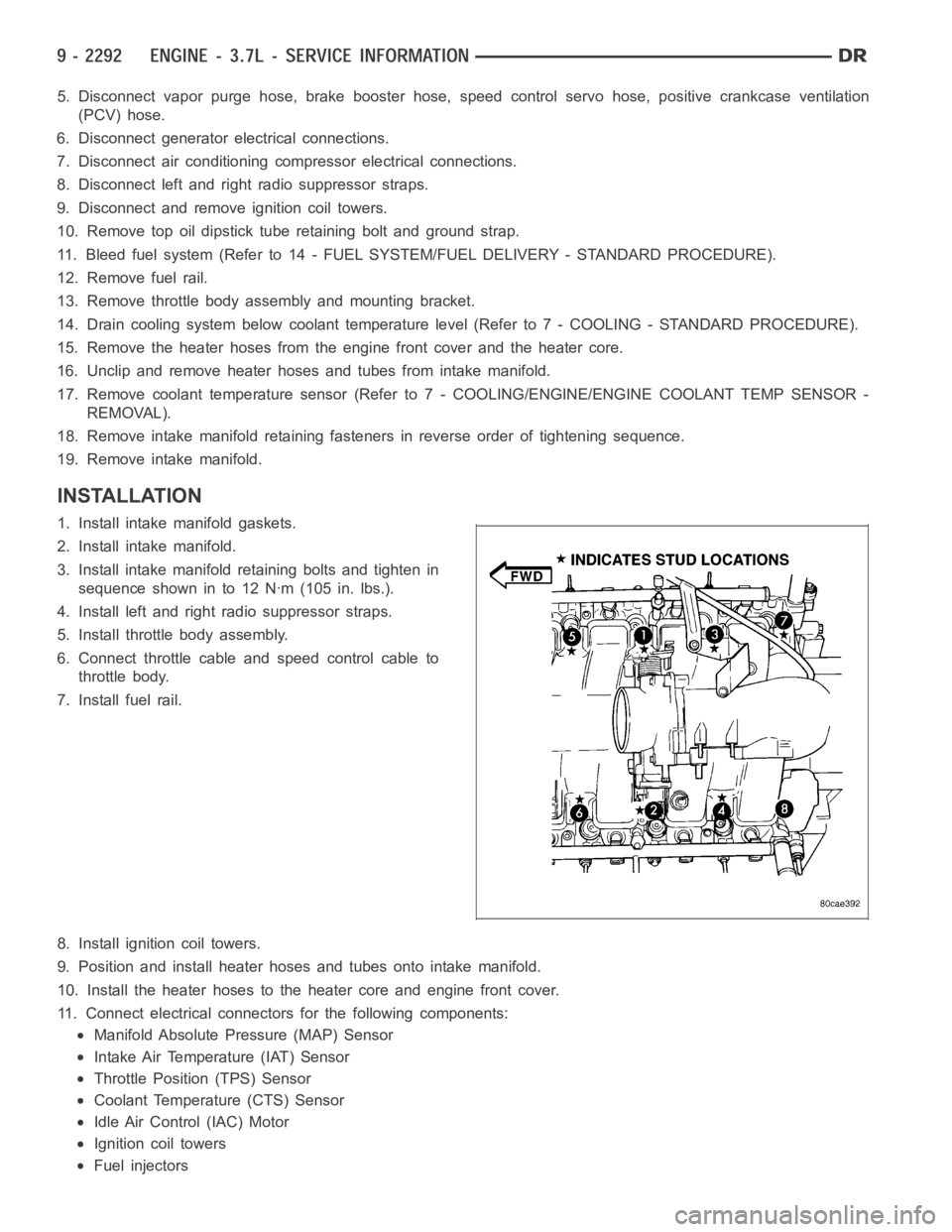
3. Install intake manifold retaining bolts and tighten in
sequence shown in to 12 Nꞏm (105 in. lbs.).
4. Install left and right radio suppressor straps.
5. Install throttle body assembly.
6. Connect throttle cable and speed control cable to
throttle body.
7. Install fuel rail.
8. Install ignition coil towers.
9. Position and install heater hoses and tubes onto intake manifold.
10. Install the heater hoses to the heater core and engine front cover.
11. Connect electrical connectors for the following components:
Manifold Absolute Pressure (MAP) Sensor
Intake Air Temperature (IAT) Sensor
Throttle Position (TPS) Sensor
Coolant Temperature (CTS) Sensor
Idle Air Control (IAC) Motor
Ignition coil towers
Fuel injectors
Page 1634 of 5267
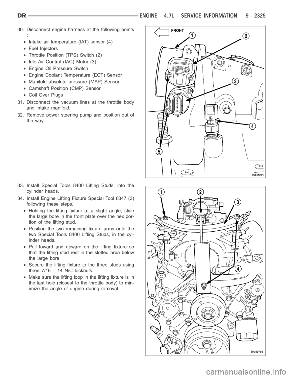
30. Disconnect engine harness at the following points
:
Intake air temperature (IAT) sensor (4)
Fuel Injectors
Throttle Position (TPS) Switch (2)
Idle Air Control (IAC) Motor (3)
Engine Oil Pressure Switch
Engine Coolant Temperature (ECT) Sensor
Manifold absolute pressure (MAP) Sensor
Camshaft Position (CMP) Sensor
Coil Over Plugs
31. Disconnect the vacuum lines at the throttle body
and intake manifold.
32. Remove power steering pump and position out of
the way.
33. Install Special Tools 8400 Lifting Studs, into the
cylinder heads.
34. Install Engine Lifting Fixture Special Tool 8347 (3)
following these steps.
Holding the lifting fixture at a slight angle, slide
the large bore in the front plate over the hex por-
tion of the lifting stud.
Position the two remaining fixture arms onto the
two Special Tools 8400 Lifting Studs, in the cyl-
inder heads.
Pull foward and upward on the lifting fixture so
that the lifting stud rest in the slotted area below
the large bore.
Secure the lifting fixture to the three studs using
three 7/16 – 14 N/C locknuts.
Make sure the lifting loop in the lifting fixture is in
the last hole (closest to the throttle body) to min-
imize the angle of engine during removal.
Page 1637 of 5267
6. Position generator wiring behind the oil dipstick
tube, then install the oil dipstick tube upper mount-
ing bolt.
7. Connect both left (2) and right (3) side body ground
straps.
8. Install power steering pump.
9. Connect fuel supply line quick connect fitting (Refer
to 14 - FUEL SYSTEM/FUEL DELIVERY/QUICK
CONNECT FITTING - STANDARD PROCEDURE).
10. Connect the vacuum lines at the throttle body and
intake manifold.
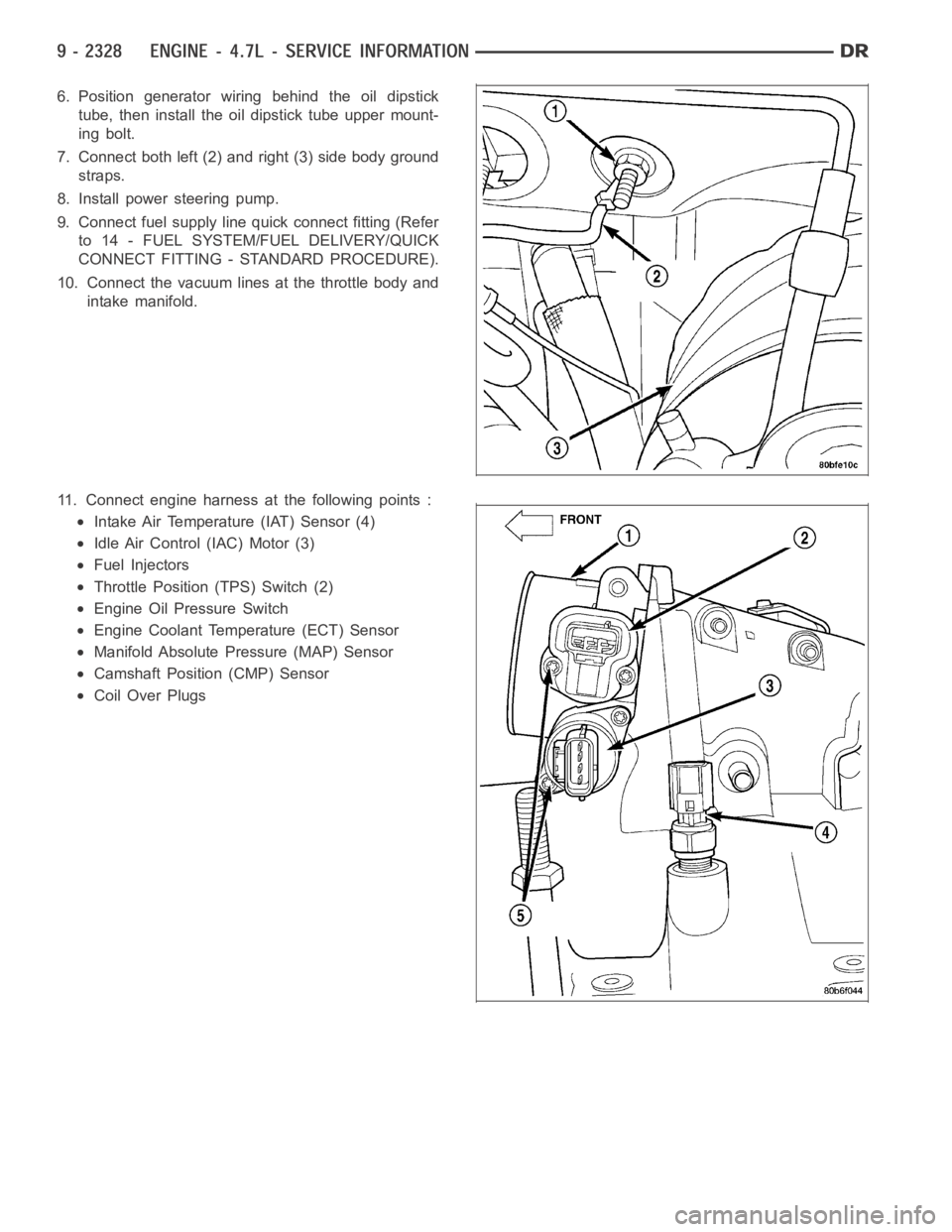
11. Connect engine harness at the following points :
Intake Air Temperature (IAT) Sensor (4)
Idle Air Control (IAC) Motor (3)
Fuel Injectors
Throttle Position (TPS) Switch (2)
Engine Oil Pressure Switch
Engine Coolant Temperature (ECT) Sensor
Manifold Absolute Pressure (MAP) Sensor
Camshaft Position (CMP) Sensor
Coil Over Plugs
Page 1734 of 5267
INSTALLATION
1. Install intake manifold gaskets.
2. Position intake manifold.
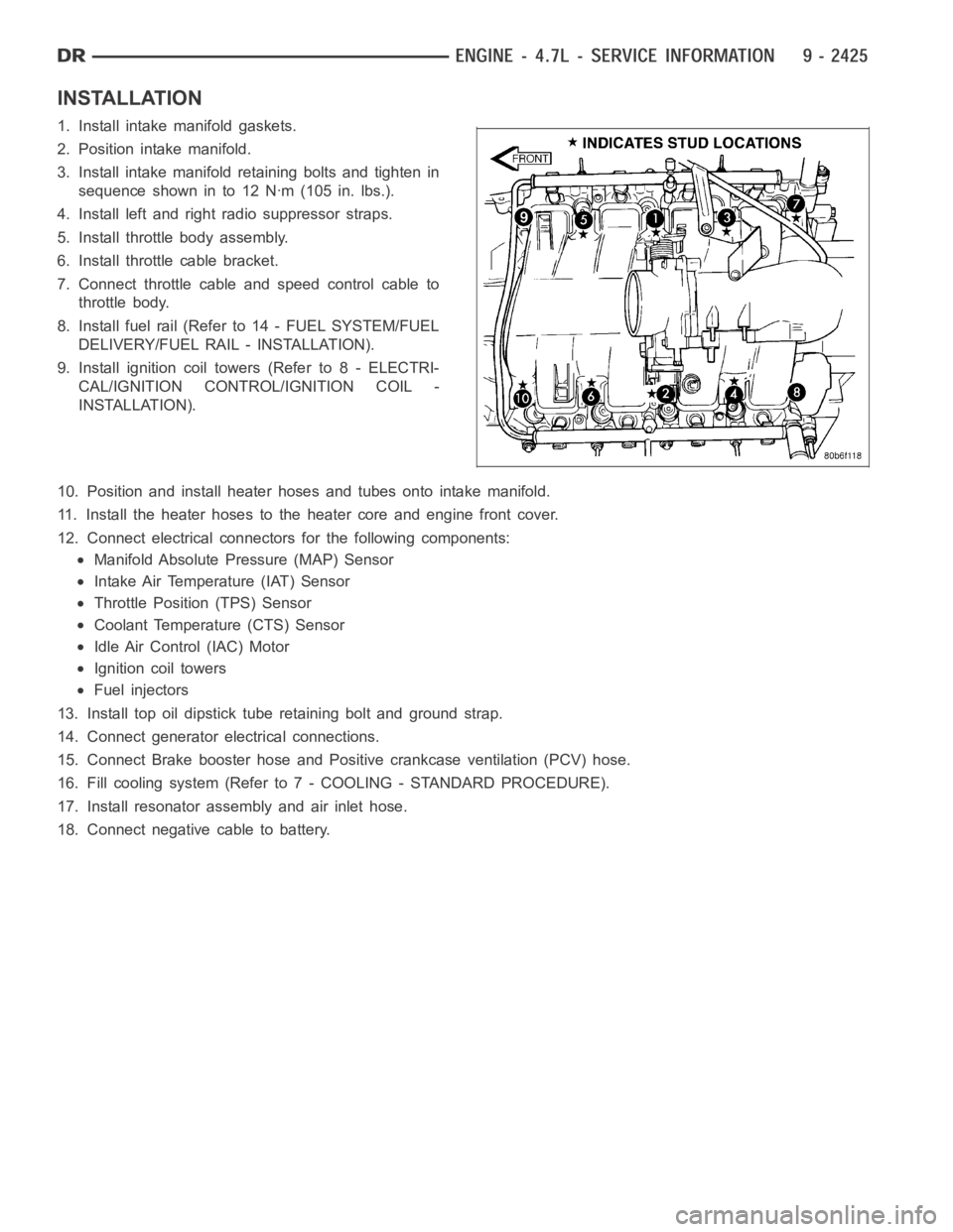
3. Install intake manifold retaining bolts and tighten in
sequence shown in to 12 Nꞏm (105 in. lbs.).
4. Install left and right radio suppressor straps.
5. Install throttle body assembly.
6. Install throttle cable bracket.
7. Connect throttle cable and speed control cable to
throttle body.
8. Install fuel rail (Refer to 14 - FUEL SYSTEM/FUEL
DELIVERY/FUEL RAIL - INSTALLATION).
9. Install ignition coil towers (Refer to 8 - ELECTRI-
CAL/IGNITION CONTROL/IGNITION COIL -
INSTALLATION).
10. Position and install heater hoses and tubes onto intake manifold.
11. Install the heater hoses to the heater core and engine front cover.
12. Connect electrical connectors for the following components:
Manifold Absolute Pressure (MAP) Sensor
Intake Air Temperature (IAT) Sensor
Throttle Position (TPS) Sensor
Coolant Temperature (CTS) Sensor
Idle Air Control (IAC) Motor
Ignition coil towers
Fuel injectors
13. Install top oil dipstick tube retaining bolt and ground strap.
14. Connect generator electrical connections.
15. Connect Brake booster hose and Positive crankcase ventilation (PCV) hose.
16. Fill cooling system (Refer to 7 - COOLING - STANDARD PROCEDURE).
17. Install resonator assembly and air inlet hose.
18. Connect negative cable to battery.
Page 1907 of 5267
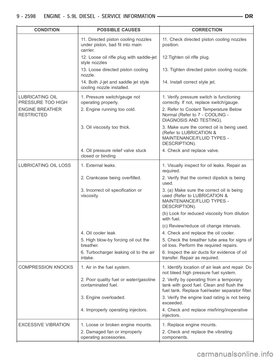
CONDITION POSSIBLE CAUSES CORRECTION
11. Directed piston cooling nozzles
under piston, bad fit into main
carrier.11. Check directed piston cooling nozzles
position.
12. Loose oil rifle plug with saddle-jet
style nozzles12.Tighten oil rifle plug.
13. Loose directed piston cooling
nozzle.13. Tighten directed piston cooling nozzle.
14. Both J-jet and saddle jet style
cooling nozzle installed.14. Install correct style jet.
LUBRICATING OIL
PRESSURE TOO HIGH1. Pressure switch/gauge not
operating properly.1. Verify pressure switch is functioning
correctly. If not, replace switch/gauge.
ENGINE BREATHER
RESTRICTED2. Engine running too cold. 2. Refer to Coolant Temperature Below
Normal (Refer to 7 - COOLING -
DIAGNOSIS AND TESTING).
3. Oil viscosity too thick. 3. Make sure the correct oil is being used.
(Refer to LUBRICATION &
MAINTENANCE/FLUID TYPES -
DESCRIPTION).
4. Oil pressure relief valve stuck
closed or binding4. Check and replace valve.
LUBRICATING OIL LOSS 1. External leaks. 1. Visually inspect for oil leaks.Repair as
required.
2. Crankcase being overfilled. 2. Verify that the correct dipstick is being
used.
3. Incorrect oil specification or
viscosity.3. (a) Make sure the correct oil is being
used (Refer to LUBRICATION &
MAINTENANCE/FLUID TYPES -
DESCRIPTION).
(b) Look for reduced viscosity from dilution
with fuel.
(c) Review/reduce oil change intervals.
4. Oil cooler leak 4. Check and replace the oil cooler.
5. High blow-by forcing oil out the
breather.5. Check the breather tube area for signs of
oil loss. Perform the required repairs.
6. Turbocharger leaking oil to the air
intake.6. Inspect the air ducts for evidence of oil
transfer. Repair as required.
COMPRESSION KNOCKS 1. Air in the fuel system. 1. Identify location of air leak and repair. Do
not bleed high pressure fuel system.
2. Poor quality fuel or water/gasoline
contaminated fuel.2. Verify by operating from a temporary
tank with good fuel. Clean and flush the
fuel tank. Replace fuel/water separator filter.
3. Engine overloaded. 3. Verify the engine load rating is not being
exceeded.
4. Improperly operating injectors. 4. Check and replace misfiring/inoperative
injectors.
EXCESSIVE VIBRATION 1. Loose or broken engine mounts. 1. Replace engine mounts.
2. Damaged fan or improperly
operating accessories.2. Check and replace the vibrating
components.
Page 1909 of 5267
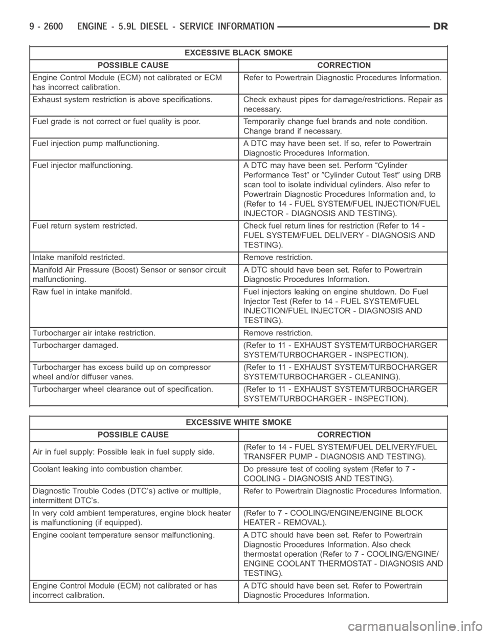
EXCESSIVE BLACK SMOKE
POSSIBLE CAUSE CORRECTION
Engine Control Module (ECM) not calibrated or ECM
has incorrect calibration.Refer to Powertrain Diagnostic Procedures Information.
Exhaust system restriction is above specifications. Check exhaust pipesfor damage/restrictions. Repair as
necessary.
Fuel grade is not correct or fuel quality is poor. Temporarily change fuel brands and note condition.
Change brand if necessary.
Fuel injection pump malfunctioning. A DTC may have been set. If so, refer toPowertrain
Diagnostic Procedures Information.
Fuel injector malfunctioning. A DTC may have been set. Perform “Cylinder
Performance Test
orCylinder Cutout Testusing DRB
scan tool to isolate individual cylinders. Also refer to
Powertrain Diagnostic Procedures Information and, to
(Refer to 14 - FUEL SYSTEM/FUEL INJECTION/FUEL
INJECTOR - DIAGNOSIS AND TESTING).
Fuel return system restricted. Check fuel return lines for restriction (Refer to 14 -
FUEL SYSTEM/FUEL DELIVERY - DIAGNOSIS AND
TESTING).
Intake manifold restricted. Remove restriction.
Manifold Air Pressure (Boost) Sensor or sensor circuit
malfunctioning.A DTC should have been set. Refer to Powertrain
Diagnostic Procedures Information.
Raw fuel in intake manifold. Fuel injectors leaking on engine shutdown. DoFuel
Injector Test (Refer to 14 - FUEL SYSTEM/FUEL
INJECTION/FUEL INJECTOR - DIAGNOSIS AND
TESTING).
Turbocharger air intake restriction. Remove restriction.
Turbocharger damaged. (Refer to 11 - EXHAUST SYSTEM/TURBOCHARGER
SYSTEM/TURBOCHARGER - INSPECTION).
Turbocharger has excess build up on compressor
wheel and/or diffuser vanes.(Refer to 11 - EXHAUST SYSTEM/TURBOCHARGER
SYSTEM/TURBOCHARGER - CLEANING).
Turbocharger wheel clearance out of specification. (Refer to 11 - EXHAUSTSYSTEM/TURBOCHARGER
SYSTEM/TURBOCHARGER - INSPECTION).
EXCESSIVE WHITE SMOKE
POSSIBLE CAUSE CORRECTION
Air in fuel supply: Possible leak in fuel supply side.(Refer to 14 - FUEL SYSTEM/FUEL DELIVERY/FUEL
TRANSFER PUMP - DIAGNOSIS AND TESTING).
Coolant leaking into combustion chamber. Do pressure test of cooling system (Refer to 7 -
COOLING - DIAGNOSIS AND TESTING).
Diagnostic Trouble Codes (DTC’s) active or multiple,
intermittent DTC’s.Refer to Powertrain Diagnostic Procedures Information.
In very cold ambient temperatures, engine block heater
is malfunctioning (if equipped).(Refer to 7 - COOLING/ENGINE/ENGINE BLOCK
HEATER - REMOVAL).
Engine coolant temperature sensor malfunctioning. A DTC should have beenset. Refer to Powertrain
Diagnostic Procedures Information. Also check
thermostat operation (Refer to 7 - COOLING/ENGINE/
ENGINE COOLANT THERMOSTAT - DIAGNOSIS AND
TESTING).
Engine Control Module (ECM) not calibrated or has
incorrect calibration.A DTC should have been set. Refer to Powertrain
Diagnostic Procedures Information.
Page 1912 of 5267
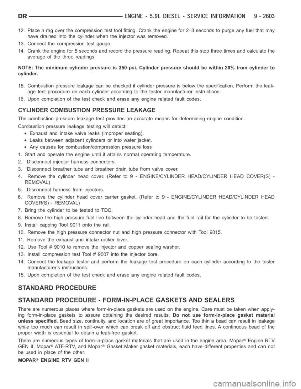
12. Place a rag over the compression test tool fitting. Crank the engine for2–3 seconds to purge any fuel that may
have drained into the cylinder when the injector was removed.
13. Connect the compression test gauge.
14. Crank the engine for 5 seconds and record the pressure reading. Repeat this step three times and calculate the
average of the three readings.
NOTE: The minimum cylinder pressure is 350 psi. Cylinder pressure should be within 20% from cylinder to
cylinder.
15. Combustion pressure leakage can be checked if cylinder pressure is below the specification. Perform the leak-
age test procedure on each cylinder according to the tester manufacturer instructions.
16. Upon completion of the test check and erase any engine related fault codes.
CYLINDER COMBUSTION PRESSURE LEAKAGE
The combustion pressure leakage test provides an accurate means for determining engine condition.
Combustion pressure leakage testing will detect:
Exhaust and intake valve leaks (improper seating).
Leaks between adjacent cylinders or into water jacket.
Any causes for combustion/compression pressure loss
1. Start and operate the engine until it attains normal operating temperature.
2. Disconnect injector harness connectors.
3. Disconnect breather tube and breather drain tube from valve cover.
4. Remove the cylinder head cover. (Refer to 9 - ENGINE/CYLINDER HEAD/CYLINDER HEAD COVER(S) -
REMOVAL)
5. Disconnect harness from injectors.
6. Remove the cylinder head cover carrier gasket. (Refer to 9 - ENGINE/CYLINDER HEAD/CYLINDER HEAD
COVER(S) - REMOVAL)
7. BringthecylindertobetestedtoTDC.
8. Remove the high pressure fuel line between the cylinder head and the fuelrail for the cylinder to be tested.
9. Install capping Tool 9011 onto the rail.
10. Remove the high pressure connector nut and high pressure connector with Tool 9015.
11. Remove the exhaust and intake rocker lever.
12. Use Tool # 9010 to remove the injector and copper sealing washer.
13. Install compression test Tool # 9007 into the injector bore.
14. Connect the leakage tester and perform the leakage test procedure on each cylinder according to the tester
manufacturer’s instructions.
15. Upon completion of the test check and erase any engine related fault codes.
STANDARD PROCEDURE
STANDARD PROCEDURE - FORM-IN-PLACE GASKETS AND SEALERS
There are numerous places where form-in-place gaskets are used on the engine. Care must be taken when apply-
ing form-in-place gaskets to assure obtaining the desired results.Do not use form-in-place gasket material
unless specified.Bead size, continuity, and location are of great importance. Too thin a bead can result in leakage
while too much can result in spill-overwhich can break off and obstruct fluid feed lines. A continuous bead of the
proper width is essential to obtain a leak-free gasket.
There are numerous types of form-in-place gasket materials that are used in the engine area. Mopar
Engine RTV
GEN II, Mopar
ATF-RTV, and MoparGasket Maker gasket materials, each have different properties and can not
be used in place of the other.
MOPAR
ENGINE RTV GEN II
Page 1914 of 5267
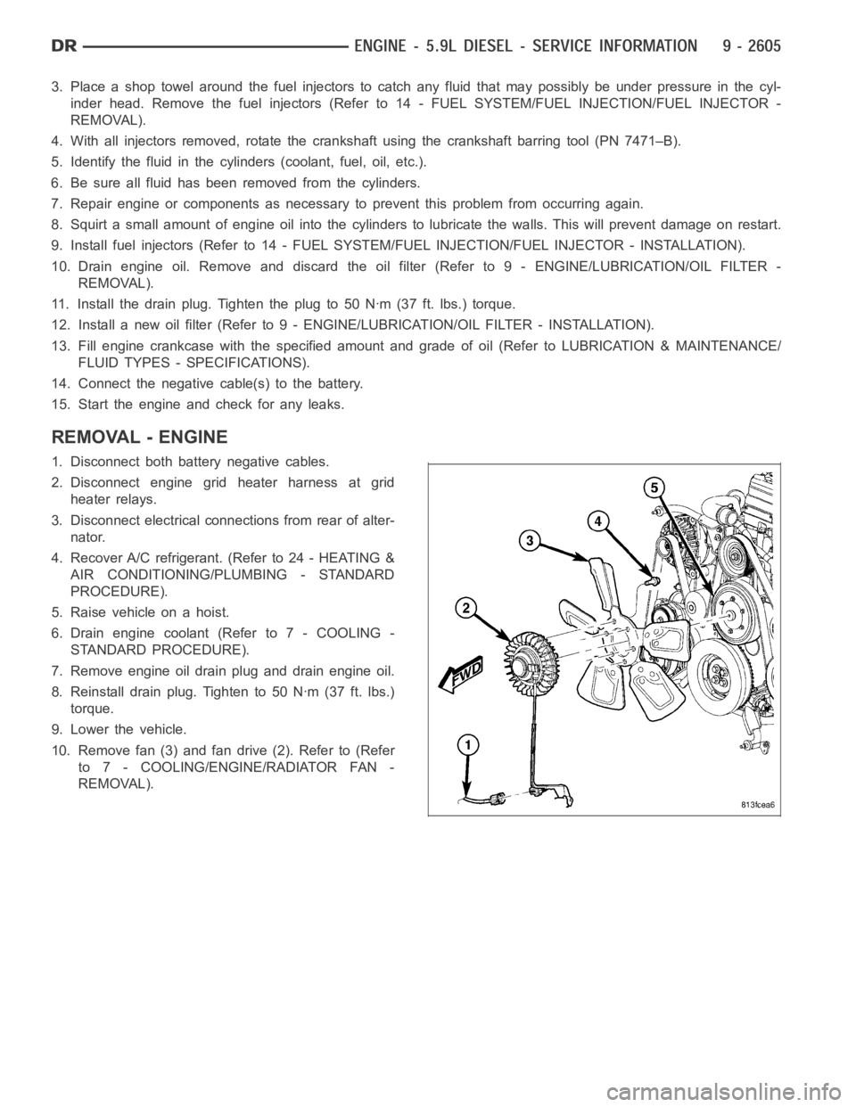
3. Place a shop towel around the fuel injectors to catch any fluid that may possibly be under pressure in the cyl-
inder head. Remove the fuel injectors (Refer to 14 - FUEL SYSTEM/FUEL INJECTION/FUEL INJECTOR -
REMOVAL).
4. With all injectors removed, rotatethe crankshaft using the crankshaftbarring tool (PN 7471–B).
5. Identify the fluid in the cylinders (coolant, fuel, oil, etc.).
6. Be sure all fluid has been removed from the cylinders.
7. Repair engine or components as necessary to prevent this problem from occurring again.
8. Squirt a small amount of engine oil into the cylinders to lubricate the walls. This will prevent damage on restart.
9. Install fuel injectors (Refer to 14 - FUEL SYSTEM/FUEL INJECTION/FUEL INJECTOR - INSTALLATION).
10. Drain engine oil. Remove and discard the oil filter (Refer to 9 - ENGINE/LUBRICATION/OIL FILTER -
REMOVAL).
11. Installthedrainplug.Tightentheplugto50Nꞏm(37ft.lbs.)torque.
12. Install a new oil filter (Refer to 9 - ENGINE/LUBRICATION/OIL FILTER - INSTALLATION).
13. Fill engine crankcase with the specified amount and grade of oil (Referto LUBRICATION & MAINTENANCE/
FLUID TYPES - SPECIFICATIONS).
14. Connect the negative cable(s) to the battery.
15. Start the engine and check for any leaks.
REMOVAL - ENGINE
1. Disconnect both battery negative cables.
2. Disconnect engine grid heater harness at grid
heater relays.
3. Disconnect electrical connections from rear of alter-
nator.
4. Recover A/C refrigerant. (Refer to 24 - HEATING &
AIR CONDITIONING/PLUMBING - STANDARD
PROCEDURE).
5. Raise vehicle on a hoist.
6. Drain engine coolant (Refer to 7 - COOLING -
STANDARD PROCEDURE).
7. Remove engine oil drain plug and drain engine oil.
8. Reinstall drain plug. Tighten to 50 Nꞏm (37 ft. lbs.)
torque.
9. Lower the vehicle.
10. Remove fan (3) and fan drive (2). Refer to (Refer
to 7 - COOLING/ENGINE/RADIATOR FAN -
REMOVAL).
Page 1917 of 5267
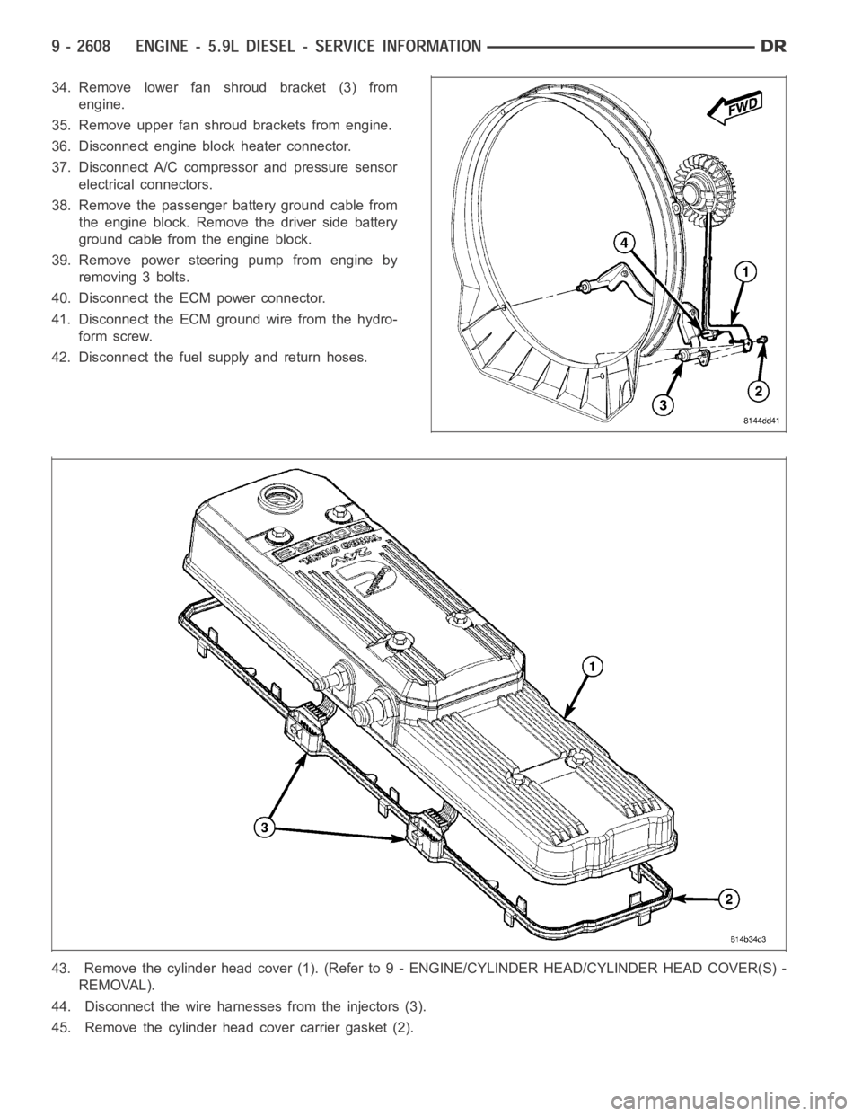
34. Remove lower fan shroud bracket (3) from
engine.
35. Remove upper fan shroud brackets from engine.
36. Disconnect engine block heater connector.
37. Disconnect A/C compressor and pressure sensor
electrical connectors.
38. Remove the passenger battery ground cable from
the engine block. Remove the driver side battery
ground cable from the engine block.
39. Remove power steering pump from engine by
removing 3 bolts.
40. Disconnect the ECM power connector.
41. Disconnect the ECM ground wire from the hydro-
form screw.
42. Disconnect the fuel supply and return hoses.
43. Remove the cylinder head cover (1). (Refer to 9 - ENGINE/CYLINDER HEAD/CYLINDER HEAD COVER(S) -
REMOVAL).
44. Disconnect the wire harnesses from the injectors (3).
45. Remove the cylinder head cover carrier gasket (2).
Page 1919 of 5267
INSTALLATION - ENGINE
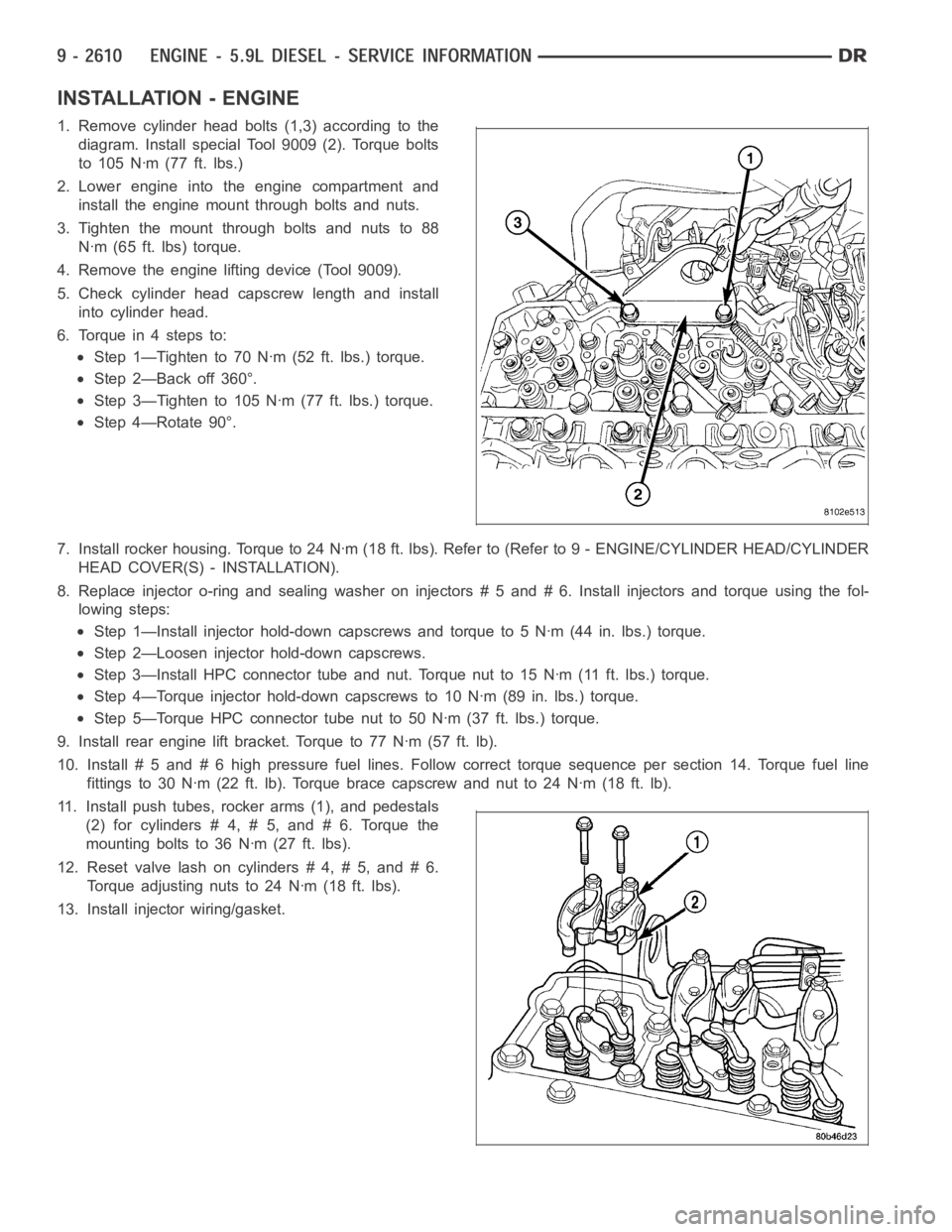
1. Remove cylinder head bolts (1,3) according to the
diagram. Install special Tool 9009 (2). Torque bolts
to 105 Nꞏm (77 ft. lbs.)
2. Lower engine into the engine compartment and
install the engine mount through bolts and nuts.
3. Tighten the mount through bolts and nuts to 88
Nꞏm (65 ft. lbs) torque.
4. Remove the engine lifting device (Tool 9009).
5. Check cylinder head capscrew length and install
into cylinder head.
6. Torque in 4 steps to:
Step 1—Tighten to 70 Nꞏm (52 ft. lbs.) torque.
Step 2—Back off 360°.
Step 3—Tighten to 105 Nꞏm (77 ft. lbs.) torque.
Step 4—Rotate 90°.
7. Install rocker housing. Torque to 24 Nꞏm (18 ft. lbs). Refer to (Refer to 9- ENGINE/CYLINDER HEAD/CYLINDER
HEAD COVER(S) - INSTALLATION).
8. Replace injector o-ring and sealing washer on injectors # 5 and # 6. Install injectors and torque using the fol-
lowing steps:
Step 1—Install injector hold-down capscrews and torque to 5 Nꞏm (44 in. lbs.) torque.
Step 2—Loosen injector hold-down capscrews.
Step 3—Install HPC connector tube and nut. Torque nut to 15 Nꞏm (11 ft. lbs.)torque.
Step 4—Torque injector hold-down capscrews to 10 Nꞏm (89 in. lbs.) torque.
Step 5—Torque HPC connector tube nut to 50 Nꞏm (37 ft. lbs.) torque.
9. Install rear engine lift bracket. Torque to 77 Nꞏm (57 ft. lb).
10. Install # 5 and # 6 high pressure fuel lines. Follow correct torque sequence per section 14. Torque fuel line
fittings to 30 Nꞏm (22 ft. lb). Torque brace capscrew and nut to 24 Nꞏm (18 ft.lb).
11. Install push tubes, rocker arms (1), and pedestals
(2) for cylinders # 4, # 5, and # 6. Torque the
mounting bolts to 36 Nꞏm (27 ft. lbs).
12. Reset valve lash on cylinders # 4, # 5, and # 6.
Torque adjusting nuts to 24 Nꞏm (18 ft. lbs).
13. Install injector wiring/gasket.