torque DODGE TOWN AND COUNTRY 2001 Service Manual
[x] Cancel search | Manufacturer: DODGE, Model Year: 2001, Model line: TOWN AND COUNTRY, Model: DODGE TOWN AND COUNTRY 2001Pages: 2321, PDF Size: 68.09 MB
Page 587 of 2321
(2) Remove cover from seat belt turning loop.
(3) Remove bolt attaching turning loop to shoulder
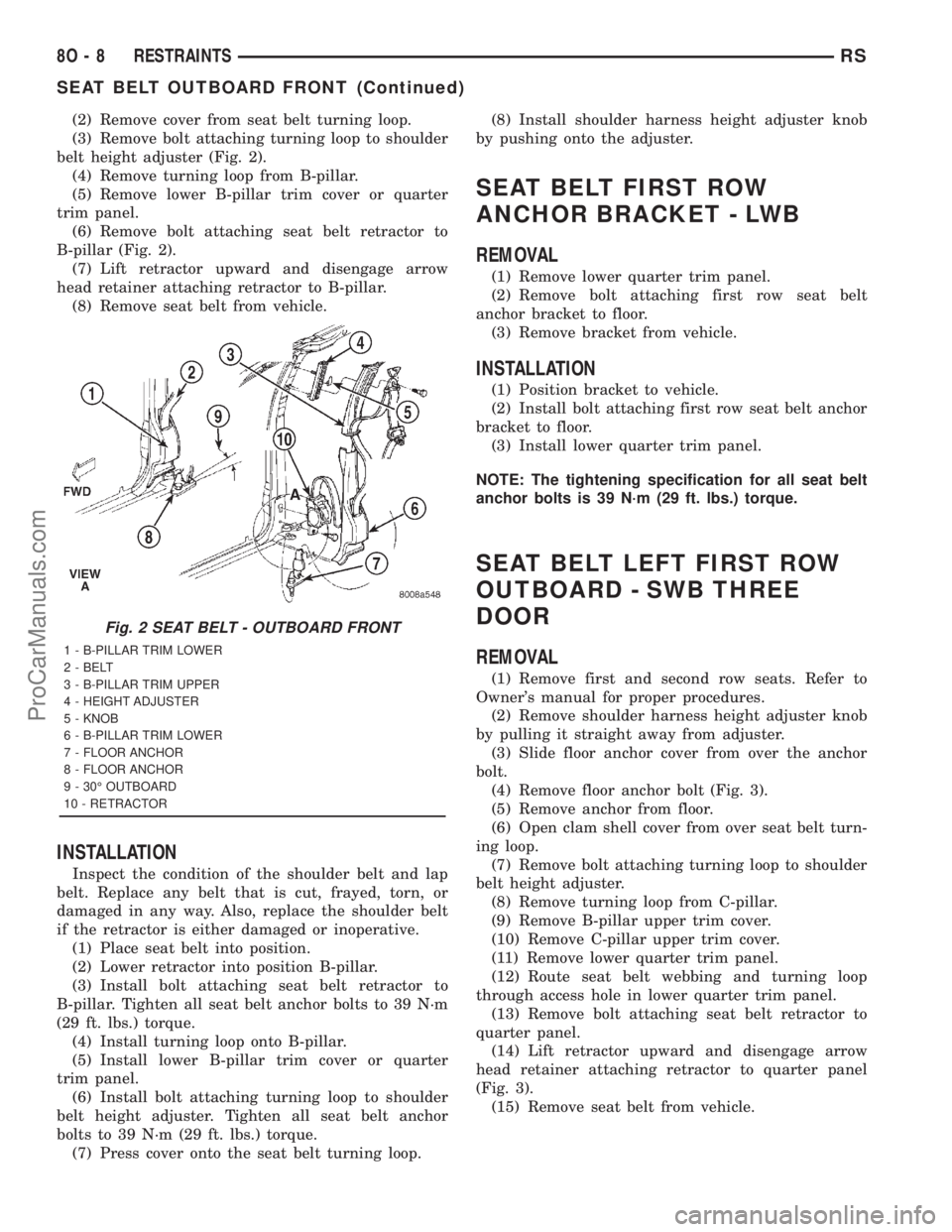
belt height adjuster (Fig. 2).
(4) Remove turning loop from B-pillar.
(5) Remove lower B-pillar trim cover or quarter
trim panel.
(6) Remove bolt attaching seat belt retractor to
B-pillar (Fig. 2).
(7) Lift retractor upward and disengage arrow
head retainer attaching retractor to B-pillar.
(8) Remove seat belt from vehicle.
INSTALLATION
Inspect the condition of the shoulder belt and lap
belt. Replace any belt that is cut, frayed, torn, or
damaged in any way. Also, replace the shoulder belt
if the retractor is either damaged or inoperative.
(1) Place seat belt into position.
(2) Lower retractor into position B-pillar.
(3) Install bolt attaching seat belt retractor to
B-pillar. Tighten all seat belt anchor bolts to 39 N´m
(29 ft. lbs.) torque.
(4) Install turning loop onto B-pillar.
(5) Install lower B-pillar trim cover or quarter
trim panel.
(6) Install bolt attaching turning loop to shoulder
belt height adjuster. Tighten all seat belt anchor
bolts to 39 N´m (29 ft. lbs.) torque.
(7) Press cover onto the seat belt turning loop.(8) Install shoulder harness height adjuster knob
by pushing onto the adjuster.
SEAT BELT FIRST ROW
ANCHOR BRACKET - LWB
REMOVAL
(1) Remove lower quarter trim panel.
(2) Remove bolt attaching first row seat belt
anchor bracket to floor.
(3) Remove bracket from vehicle.
INSTALLATION
(1) Position bracket to vehicle.
(2) Install bolt attaching first row seat belt anchor
bracket to floor.
(3) Install lower quarter trim panel.
NOTE: The tightening specification for all seat belt
anchor bolts is 39 N´m (29 ft. lbs.) torque.
SEAT BELT LEFT FIRST ROW
OUTBOARD - SWB THREE
DOOR
REMOVAL
(1) Remove first and second row seats. Refer to
Owner's manual for proper procedures.
(2) Remove shoulder harness height adjuster knob
by pulling it straight away from adjuster.
(3) Slide floor anchor cover from over the anchor
bolt.
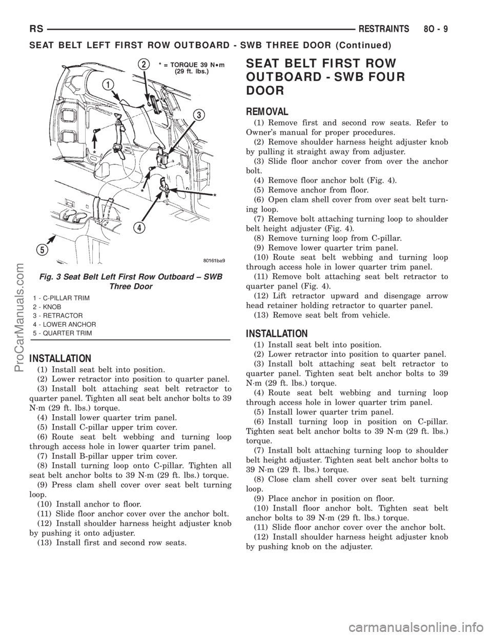
(4) Remove floor anchor bolt (Fig. 3).
(5) Remove anchor from floor.
(6) Open clam shell cover from over seat belt turn-
ing loop.
(7) Remove bolt attaching turning loop to shoulder
belt height adjuster.
(8) Remove turning loop from C-pillar.
(9) Remove B-pillar upper trim cover.
(10) Remove C-pillar upper trim cover.
(11) Remove lower quarter trim panel.
(12) Route seat belt webbing and turning loop
through access hole in lower quarter trim panel.
(13) Remove bolt attaching seat belt retractor to
quarter panel.
(14) Lift retractor upward and disengage arrow
head retainer attaching retractor to quarter panel
(Fig. 3).
(15) Remove seat belt from vehicle.
Fig. 2 SEAT BELT - OUTBOARD FRONT
1 - B-PILLAR TRIM LOWER
2 - BELT
3 - B-PILLAR TRIM UPPER
4 - HEIGHT ADJUSTER
5 - KNOB
6 - B-PILLAR TRIM LOWER
7 - FLOOR ANCHOR
8 - FLOOR ANCHOR
9 - 30É OUTBOARD
10 - RETRACTOR
8O - 8 RESTRAINTSRS
SEAT BELT OUTBOARD FRONT (Continued)
ProCarManuals.com
Page 588 of 2321
INSTALLATION
(1) Install seat belt into position.
(2) Lower retractor into position to quarter panel.
(3) Install bolt attaching seat belt retractor to
quarter panel. Tighten all seat belt anchor bolts to 39
N´m (29 ft. lbs.) torque.
(4) Install lower quarter trim panel.
(5) Install C-pillar upper trim cover.
(6) Route seat belt webbing and turning loop
through access hole in lower quarter trim panel.
(7) Install B-pillar upper trim cover.
(8) Install turning loop onto C-pillar. Tighten all
seat belt anchor bolts to 39 N´m (29 ft. lbs.) torque.
(9) Press clam shell cover over seat belt turning
loop.
(10) Install anchor to floor.
(11) Slide floor anchor cover over the anchor bolt.
(12) Install shoulder harness height adjuster knob
by pushing it onto adjuster.
(13) Install first and second row seats.
SEAT BELT FIRST ROW
OUTBOARD - SWB FOUR
DOOR
REMOVAL
(1) Remove first and second row seats. Refer to
Owner's manual for proper procedures.
(2) Remove shoulder harness height adjuster knob
by pulling it straight away from adjuster.
(3) Slide floor anchor cover from over the anchor
bolt.
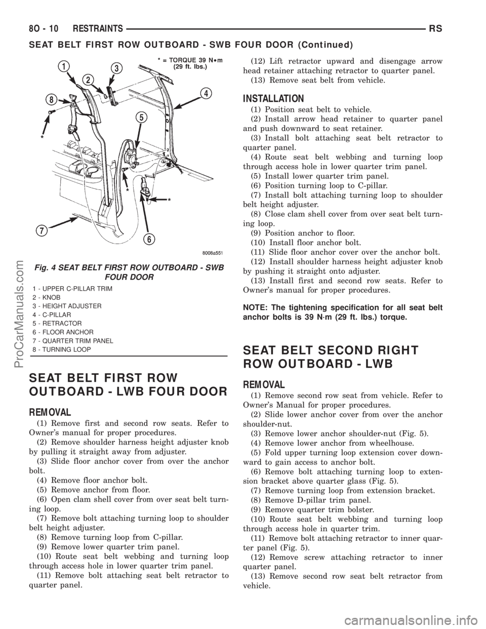
(4) Remove floor anchor bolt (Fig. 4).
(5) Remove anchor from floor.
(6) Open clam shell cover from over seat belt turn-
ing loop.
(7) Remove bolt attaching turning loop to shoulder
belt height adjuster (Fig. 4).
(8) Remove turning loop from C-pillar.
(9) Remove lower quarter trim panel.
(10) Route seat belt webbing and turning loop
through access hole in lower quarter trim panel.
(11) Remove bolt attaching seat belt retractor to
quarter panel (Fig. 4).
(12) Lift retractor upward and disengage arrow
head retainer holding retractor to quarter panel.
(13) Remove seat belt from vehicle.
INSTALLATION
(1) Install seat belt into position.
(2) Lower retractor into position to quarter panel.
(3) Install bolt attaching seat belt retractor to
quarter panel. Tighten seat belt anchor bolts to 39
N´m (29 ft. lbs.) torque.
(4) Route seat belt webbing and turning loop
through access hole in lower quarter trim panel.
(5) Install lower quarter trim panel.
(6) Install turning loop in position on C-pillar.
Tighten seat belt anchor bolts to 39 N´m (29 ft. lbs.)
torque.
(7) Install bolt attaching turning loop to shoulder
belt height adjuster. Tighten seat belt anchor bolts to
39 N´m (29 ft. lbs.) torque.
(8) Close clam shell cover over seat belt turning
loop.
(9) Place anchor in position on floor.
(10) Install floor anchor bolt. Tighten seat belt
anchor bolts to 39 N´m (29 ft. lbs.) torque.
(11) Slide floor anchor cover over the anchor bolt.
(12) Install shoulder harness height adjuster knob
by pushing knob on the adjuster.
Fig. 3 Seat Belt Left First Row Outboard ± SWB
Three Door
1 - C-PILLAR TRIM
2 - KNOB
3 - RETRACTOR
4 - LOWER ANCHOR
5 - QUARTER TRIM
RSRESTRAINTS8O-9
SEAT BELT LEFT FIRST ROW OUTBOARD - SWB THREE DOOR (Continued)
ProCarManuals.com
Page 589 of 2321
SEAT BELT FIRST ROW
OUTBOARD - LWB FOUR DOOR
REMOVAL
(1) Remove first and second row seats. Refer to
Owner's manual for proper procedures.
(2) Remove shoulder harness height adjuster knob
by pulling it straight away from adjuster.
(3) Slide floor anchor cover from over the anchor
bolt.
(4) Remove floor anchor bolt.
(5) Remove anchor from floor.
(6) Open clam shell cover from over seat belt turn-
ing loop.
(7) Remove bolt attaching turning loop to shoulder
belt height adjuster.
(8) Remove turning loop from C-pillar.
(9) Remove lower quarter trim panel.
(10) Route seat belt webbing and turning loop
through access hole in lower quarter trim panel.
(11) Remove bolt attaching seat belt retractor to
quarter panel.(12) Lift retractor upward and disengage arrow
head retainer attaching retractor to quarter panel.
(13) Remove seat belt from vehicle.
INSTALLATION
(1) Position seat belt to vehicle.
(2) Install arrow head retainer to quarter panel
and push downward to seat retainer.
(3) Install bolt attaching seat belt retractor to
quarter panel.
(4) Route seat belt webbing and turning loop
through access hole in lower quarter trim panel.
(5) Install lower quarter trim panel.
(6) Position turning loop to C-pillar.
(7) Install bolt attaching turning loop to shoulder
belt height adjuster.
(8) Close clam shell cover from over seat belt turn-
ing loop.
(9) Position anchor to floor.
(10) Install floor anchor bolt.
(11) Slide floor anchor cover over the anchor bolt.
(12) Install shoulder harness height adjuster knob
by pushing it straight onto adjuster.
(13) Install first and second row seats. Refer to
Owner's manual for proper procedures.
NOTE: The tightening specification for all seat belt
anchor bolts is 39 N´m (29 ft. lbs.) torque.
SEAT BELT SECOND RIGHT
ROW OUTBOARD - LWB
REMOVAL
(1) Remove second row seat from vehicle. Refer to
Owner's Manual for proper procedures.
(2) Slide lower anchor cover from over the anchor
shoulder-nut.
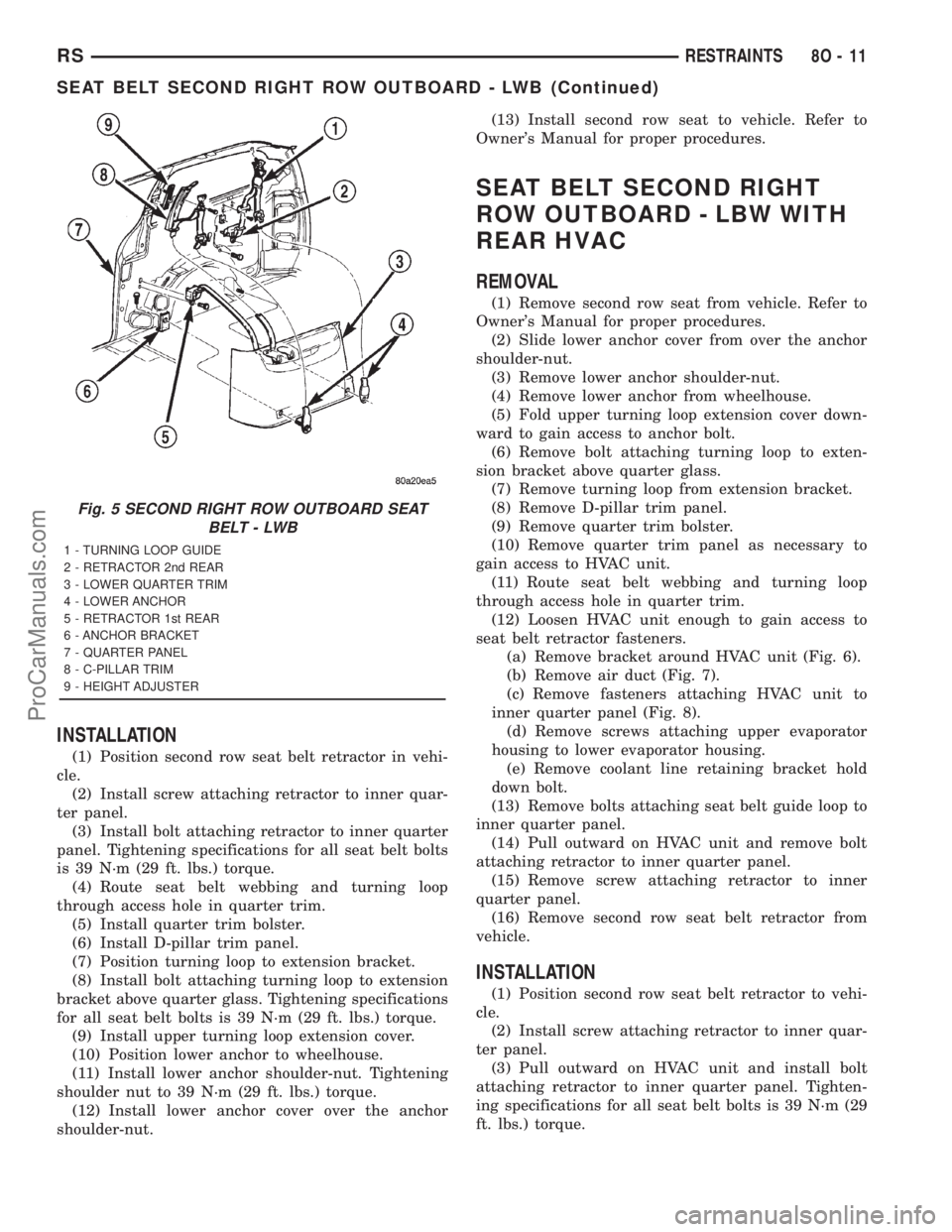
(3) Remove lower anchor shoulder-nut (Fig. 5).
(4) Remove lower anchor from wheelhouse.
(5) Fold upper turning loop extension cover down-
ward to gain access to anchor bolt.
(6) Remove bolt attaching turning loop to exten-
sion bracket above quarter glass (Fig. 5).
(7) Remove turning loop from extension bracket.
(8) Remove D-pillar trim panel.
(9) Remove quarter trim bolster.
(10) Route seat belt webbing and turning loop
through access hole in quarter trim.
(11) Remove bolt attaching retractor to inner quar-
ter panel (Fig. 5).
(12) Remove screw attaching retractor to inner
quarter panel.
(13) Remove second row seat belt retractor from
vehicle.
Fig. 4 SEAT BELT FIRST ROW OUTBOARD - SWB
FOUR DOOR
1 - UPPER C-PILLAR TRIM
2 - KNOB
3 - HEIGHT ADJUSTER
4 - C-PILLAR
5 - RETRACTOR
6 - FLOOR ANCHOR
7 - QUARTER TRIM PANEL
8 - TURNING LOOP
8O - 10 RESTRAINTSRS
SEAT BELT FIRST ROW OUTBOARD - SWB FOUR DOOR (Continued)
ProCarManuals.com
Page 590 of 2321
INSTALLATION
(1) Position second row seat belt retractor in vehi-
cle.
(2) Install screw attaching retractor to inner quar-
ter panel.
(3) Install bolt attaching retractor to inner quarter
panel. Tightening specifications for all seat belt bolts
is 39 N´m (29 ft. lbs.) torque.
(4) Route seat belt webbing and turning loop
through access hole in quarter trim.
(5) Install quarter trim bolster.
(6) Install D-pillar trim panel.
(7) Position turning loop to extension bracket.
(8) Install bolt attaching turning loop to extension
bracket above quarter glass. Tightening specifications
for all seat belt bolts is 39 N´m (29 ft. lbs.) torque.
(9) Install upper turning loop extension cover.
(10) Position lower anchor to wheelhouse.
(11) Install lower anchor shoulder-nut. Tightening
shoulder nut to 39 N´m (29 ft. lbs.) torque.
(12) Install lower anchor cover over the anchor
shoulder-nut.(13) Install second row seat to vehicle. Refer to
Owner's Manual for proper procedures.
SEAT BELT SECOND RIGHT
ROW OUTBOARD - LBW WITH
REAR HVAC
REMOVAL
(1) Remove second row seat from vehicle. Refer to
Owner's Manual for proper procedures.
(2) Slide lower anchor cover from over the anchor
shoulder-nut.
(3) Remove lower anchor shoulder-nut.
(4) Remove lower anchor from wheelhouse.
(5) Fold upper turning loop extension cover down-
ward to gain access to anchor bolt.
(6) Remove bolt attaching turning loop to exten-
sion bracket above quarter glass.
(7) Remove turning loop from extension bracket.
(8) Remove D-pillar trim panel.
(9) Remove quarter trim bolster.
(10) Remove quarter trim panel as necessary to
gain access to HVAC unit.
(11) Route seat belt webbing and turning loop
through access hole in quarter trim.
(12) Loosen HVAC unit enough to gain access to
seat belt retractor fasteners.
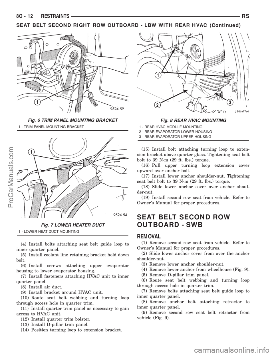
(a) Remove bracket around HVAC unit (Fig. 6).
(b) Remove air duct (Fig. 7).
(c) Remove fasteners attaching HVAC unit to
inner quarter panel (Fig. 8).
(d) Remove screws attaching upper evaporator
housing to lower evaporator housing.
(e) Remove coolant line retaining bracket hold
down bolt.
(13) Remove bolts attaching seat belt guide loop to
inner quarter panel.
(14) Pull outward on HVAC unit and remove bolt
attaching retractor to inner quarter panel.
(15) Remove screw attaching retractor to inner
quarter panel.
(16) Remove second row seat belt retractor from
vehicle.
INSTALLATION
(1) Position second row seat belt retractor to vehi-
cle.
(2) Install screw attaching retractor to inner quar-
ter panel.
(3) Pull outward on HVAC unit and install bolt
attaching retractor to inner quarter panel. Tighten-
ing specifications for all seat belt bolts is 39 N´m (29
ft. lbs.) torque.
Fig. 5 SECOND RIGHT ROW OUTBOARD SEAT
BELT - LWB
1 - TURNING LOOP GUIDE
2 - RETRACTOR 2nd REAR
3 - LOWER QUARTER TRIM
4 - LOWER ANCHOR
5 - RETRACTOR 1st REAR
6 - ANCHOR BRACKET
7 - QUARTER PANEL
8 - C-PILLAR TRIM
9 - HEIGHT ADJUSTER
RSRESTRAINTS8O-11
SEAT BELT SECOND RIGHT ROW OUTBOARD - LWB (Continued)
ProCarManuals.com
Page 591 of 2321
(4) Install bolts attaching seat belt guide loop to
inner quarter panel.
(5) Install coolant line retaining bracket hold down
bolt.
(6) Install screws attaching upper evaporator
housing to lower evaporator housing.
(7) Install fasteners attaching HVAC unit to inner
quarter panel.
(8) Install air duct.
(9) Install bracket around HVAC unit.
(10) Route seat belt webbing and turning loop
through access hole in quarter trim.
(11) Install quarter trim panel as necessary to gain
access to HVAC unit.
(12) Install quarter trim bolster.
(13) Install D-pillar trim panel.
(14) Position turning loop to extension bracket.(15) Install bolt attaching turning loop to exten-
sion bracket above quarter glass. Tightening seat belt
bolt to 39 N´m (29 ft. lbs.) torque.
(16) Pull upper turning loop extension cover
upward over anchor bolt.
(17) Install lower anchor shoulder-nut. Tightening
seat belt bolt to 39 N´m (29 ft. lbs.) torque.
(18) Slide lower anchor cover over anchor shoul-
der-nut.
(19) Install second row seat from vehicle. Refer to
Owner's Manual for proper procedures.
SEAT BELT SECOND ROW
OUTBOARD - SWB
REMOVAL
(1) Remove second row seat from vehicle. Refer to
Owner's Manual for proper procedures.
(2) Slide lower anchor cover from over the anchor
shoulder-nut.
(3) Remove lower anchor shoulder-nut.
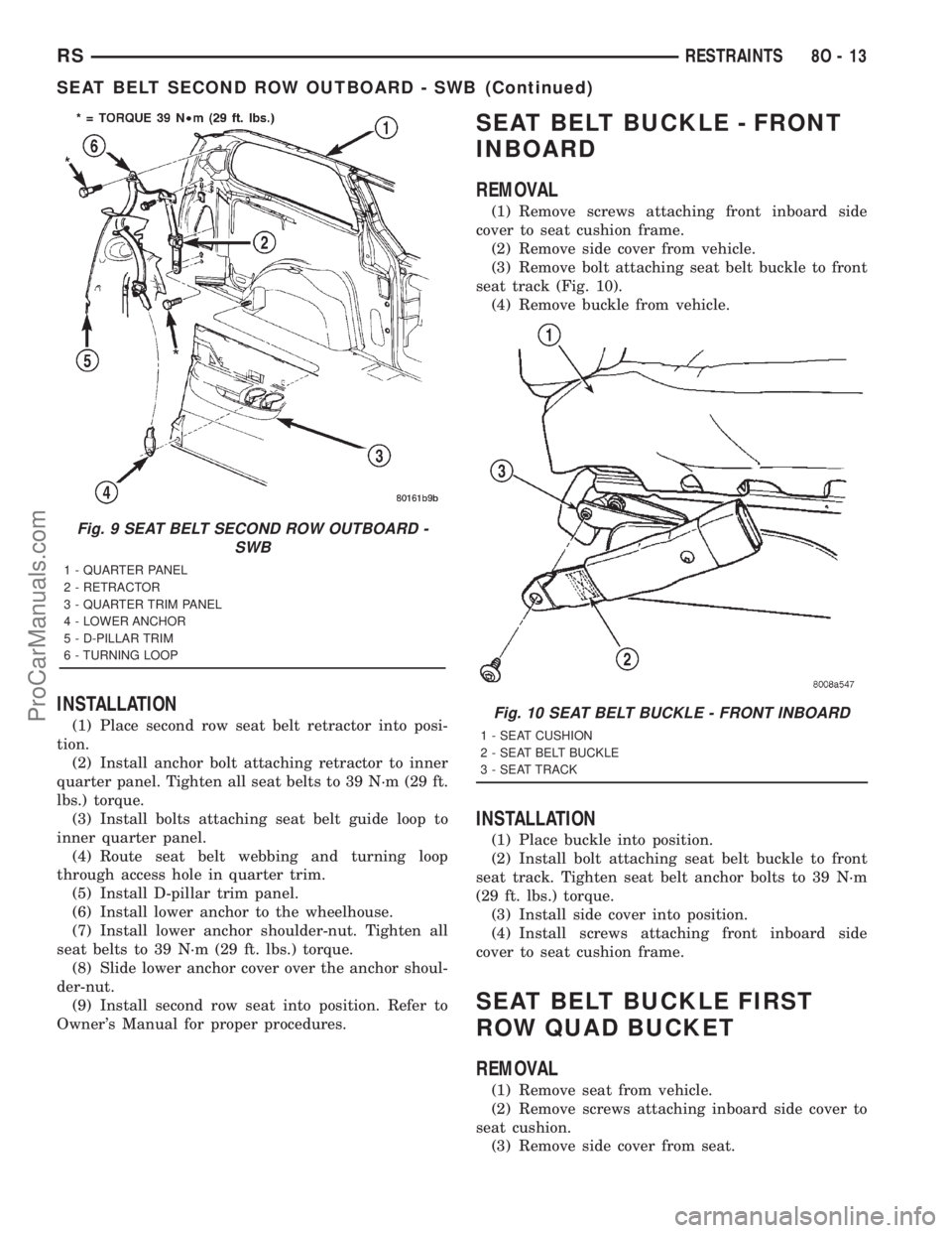
(4) Remove lower anchor from wheelhouse (Fig. 9).
(5) Remove D-pillar trim panel.
(6) Route seat belt webbing and turning loop
through access hole in quarter trim.
(7) Remove bolts attaching seat belt guide loop to
inner quarter panel.
(8) Remove anchor bolt attaching retractor to
inner quarter panel.
(9) Remove second row seat belt retractor from
vehicle (Fig. 9).
Fig. 6 TRIM PANEL MOUNTING BRACKET
1 - TRIM PANEL MOUNTING BRACKET
Fig. 7 LOWER HEATER DUCT
1 - LOWER HEAT DUCT MOUNTING
Fig. 8 REAR HVAC MOUNTING
1 - REAR HVAC MODULE MOUNTING
2 - REAR EVAPORATOR LOWER HOUSING
3 - REAR EVAPORATOR UPPER HOUSING
8O - 12 RESTRAINTSRS
SEAT BELT SECOND RIGHT ROW OUTBOARD - LBW WITH REAR HVAC (Continued)
ProCarManuals.com
Page 592 of 2321
INSTALLATION
(1) Place second row seat belt retractor into posi-
tion.
(2) Install anchor bolt attaching retractor to inner
quarter panel. Tighten all seat belts to 39 N´m (29 ft.
lbs.) torque.
(3) Install bolts attaching seat belt guide loop to
inner quarter panel.
(4) Route seat belt webbing and turning loop
through access hole in quarter trim.
(5) Install D-pillar trim panel.
(6) Install lower anchor to the wheelhouse.
(7) Install lower anchor shoulder-nut. Tighten all
seat belts to 39 N´m (29 ft. lbs.) torque.
(8) Slide lower anchor cover over the anchor shoul-
der-nut.
(9) Install second row seat into position. Refer to
Owner's Manual for proper procedures.
SEAT BELT BUCKLE - FRONT
INBOARD
REMOVAL
(1) Remove screws attaching front inboard side
cover to seat cushion frame.
(2) Remove side cover from vehicle.
(3) Remove bolt attaching seat belt buckle to front
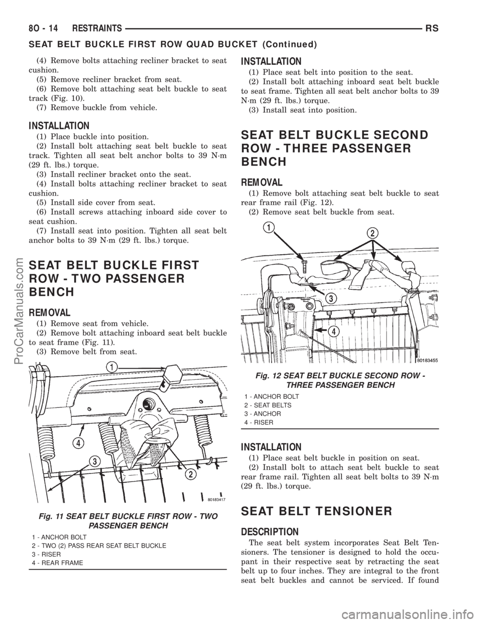
seat track (Fig. 10).
(4) Remove buckle from vehicle.
INSTALLATION
(1) Place buckle into position.
(2) Install bolt attaching seat belt buckle to front
seat track. Tighten seat belt anchor bolts to 39 N´m
(29 ft. lbs.) torque.
(3) Install side cover into position.
(4) Install screws attaching front inboard side
cover to seat cushion frame.
SEAT BELT BUCKLE FIRST
ROW QUAD BUCKET
REMOVAL
(1) Remove seat from vehicle.
(2) Remove screws attaching inboard side cover to
seat cushion.
(3) Remove side cover from seat.
Fig. 9 SEAT BELT SECOND ROW OUTBOARD -
SWB
1 - QUARTER PANEL
2 - RETRACTOR
3 - QUARTER TRIM PANEL
4 - LOWER ANCHOR
5 - D-PILLAR TRIM
6 - TURNING LOOP
Fig. 10 SEAT BELT BUCKLE - FRONT INBOARD
1 - SEAT CUSHION
2 - SEAT BELT BUCKLE
3 - SEAT TRACK
RSRESTRAINTS8O-13
SEAT BELT SECOND ROW OUTBOARD - SWB (Continued)
ProCarManuals.com
Page 593 of 2321
(4) Remove bolts attaching recliner bracket to seat
cushion.
(5) Remove recliner bracket from seat.
(6) Remove bolt attaching seat belt buckle to seat
track (Fig. 10).
(7) Remove buckle from vehicle.
INSTALLATION
(1) Place buckle into position.
(2) Install bolt attaching seat belt buckle to seat
track. Tighten all seat belt anchor bolts to 39 N´m
(29 ft. lbs.) torque.
(3) Install recliner bracket onto the seat.
(4) Install bolts attaching recliner bracket to seat
cushion.
(5) Install side cover from seat.
(6) Install screws attaching inboard side cover to
seat cushion.
(7) Install seat into position. Tighten all seat belt
anchor bolts to 39 N´m (29 ft. lbs.) torque.
SEAT BELT BUCKLE FIRST
ROW - TWO PASSENGER
BENCH
REMOVAL
(1) Remove seat from vehicle.
(2) Remove bolt attaching inboard seat belt buckle
to seat frame (Fig. 11).
(3) Remove belt from seat.
INSTALLATION
(1) Place seat belt into position to the seat.
(2) Install bolt attaching inboard seat belt buckle
to seat frame. Tighten all seat belt anchor bolts to 39
N´m (29 ft. lbs.) torque.
(3) Install seat into position.
SEAT BELT BUCKLE SECOND
ROW - THREE PASSENGER
BENCH
REMOVAL
(1) Remove bolt attaching seat belt buckle to seat
rear frame rail (Fig. 12).
(2) Remove seat belt buckle from seat.
INSTALLATION
(1) Place seat belt buckle in position on seat.
(2) Install bolt to attach seat belt buckle to seat
rear frame rail. Tighten all seat belt bolts to 39 N´m
(29 ft. lbs.) torque.
SEAT BELT TENSIONER
DESCRIPTION
The seat belt system incorporates Seat Belt Ten-
sioners. The tensioner is designed to hold the occu-
pant in their respective seat by retracting the seat
belt up to four inches. They are integral to the front
seat belt buckles and cannot be serviced. If found
Fig. 11 SEAT BELT BUCKLE FIRST ROW - TWO
PASSENGER BENCH
1 - ANCHOR BOLT
2 - TWO (2) PASS REAR SEAT BELT BUCKLE
3 - RISER
4 - REAR FRAME
Fig. 12 SEAT BELT BUCKLE SECOND ROW -
THREE PASSENGER BENCH
1 - ANCHOR BOLT
2 - SEAT BELTS
3 - ANCHOR
4 - RISER
8O - 14 RESTRAINTSRS
SEAT BELT BUCKLE FIRST ROW QUAD BUCKET (Continued)
ProCarManuals.com
Page 594 of 2321
defective they must be replaced. After an airbag
deployment, the tensioner must be replaced.
OPERATION
At the onset of an impact event, each tensioner
uses a pyrotechnic device which is triggered simulta-
neously with the airbags to rapidly retract the seat
belts. With the slack removed, the occupant's forward
motion in an impact will be reduced as will the like-
lihood of contacting interior components. After an
impact that deploys the airbags, the seat belt ten-
sioner assembly must be replaced.
The Occupant Restraint Controller (ORC) monitors
the seat belt tensioner circuit resistance and reports
active and stored Diagnostic Trouble Codes (DTC's) if
any problem is found.
Once a vehicle has been in an accident, the tensioner
must be replaced along with any deployed airbags and
broken or damaged parts. Refer to the proper Body
Diagnostic Procedures manual for diagnosis and testing.
WARNING: WHEN THE FRONT AIRBAG IS
DEPLOYED, THE TENSIONER WILL HAVE
DEPLOYED ALSO AND SHOULD BE REPLACED.
SHOULDER BELT HEIGHT
ADJUSTER
REMOVAL
(1) Remove B or C-pillar trim cover.
(2) Remove screws attaching shoulder belt height
adjuster to pillar.
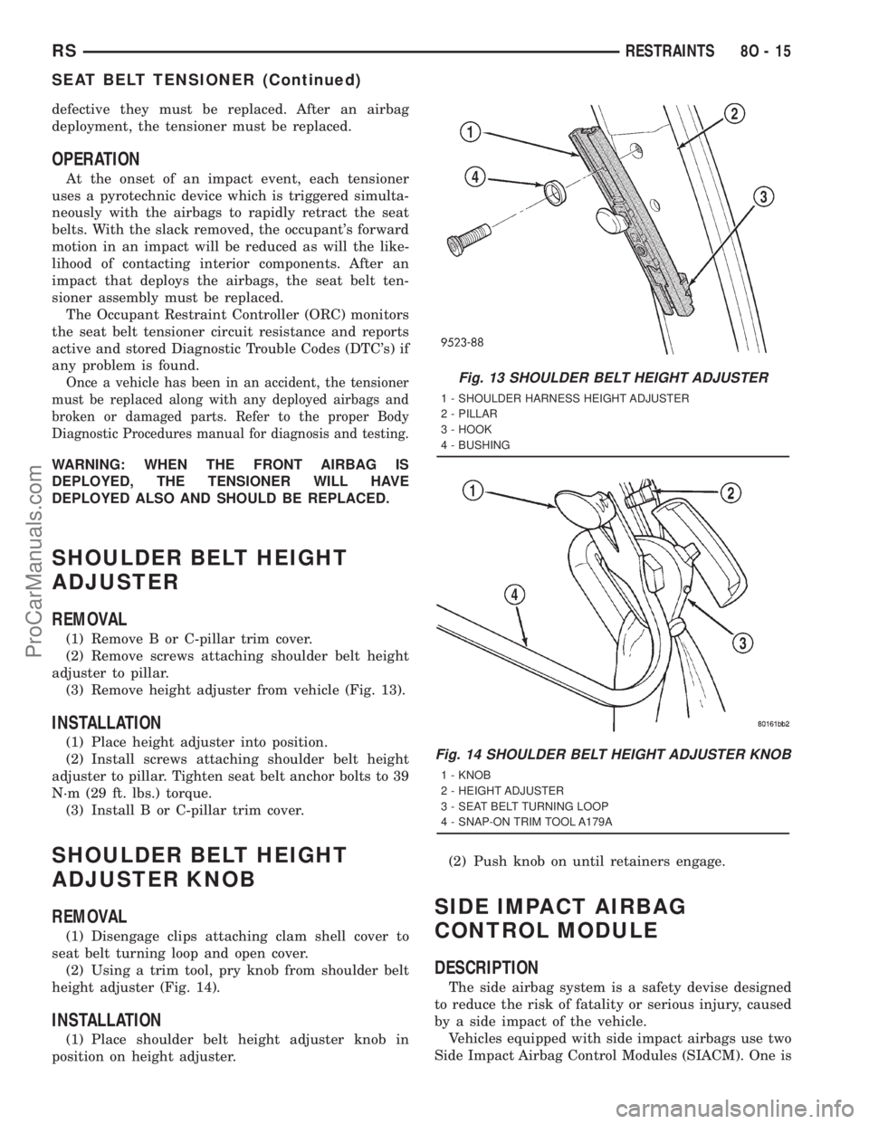
(3) Remove height adjuster from vehicle (Fig. 13).
INSTALLATION
(1) Place height adjuster into position.
(2) Install screws attaching shoulder belt height
adjuster to pillar. Tighten seat belt anchor bolts to 39
N´m (29 ft. lbs.) torque.
(3) Install B or C-pillar trim cover.
SHOULDER BELT HEIGHT
ADJUSTER KNOB
REMOVAL
(1) Disengage clips attaching clam shell cover to
seat belt turning loop and open cover.
(2) Using a trim tool, pry knob from shoulder belt
height adjuster (Fig. 14).
INSTALLATION
(1) Place shoulder belt height adjuster knob in
position on height adjuster.(2) Push knob on until retainers engage.
SIDE IMPACT AIRBAG
CONTROL MODULE
DESCRIPTION
The side airbag system is a safety devise designed
to reduce the risk of fatality or serious injury, caused
by a side impact of the vehicle.
Vehicles equipped with side impact airbags use two
Side Impact Airbag Control Modules (SIACM). One is
Fig. 13 SHOULDER BELT HEIGHT ADJUSTER
1 - SHOULDER HARNESS HEIGHT ADJUSTER
2 - PILLAR
3 - HOOK
4 - BUSHING
Fig. 14 SHOULDER BELT HEIGHT ADJUSTER KNOB
1 - KNOB
2 - HEIGHT ADJUSTER
3 - SEAT BELT TURNING LOOP
4 - SNAP-ON TRIM TOOL A179A
RSRESTRAINTS8O-15
SEAT BELT TENSIONER (Continued)
ProCarManuals.com
Page 595 of 2321
located on each respective side body B-pillar. Each
contains an impact sensor that senses a side impact
occurrence. The SIACM communicates with the ORC
via the PCI bus in order to notify the driver of any
potential side airbag system problem.
OPERATION
The impact sensor provides verification of the
direction and severity of the side impact. The right
side SIACM controls the right seat airbag. The left
side SIACM controls the left seat airbag. In the event
of a side impact the appropriate SIACM will send an
electronic signal to its airbag, deploying the airbag.
The SIACM communicates with the Occupant
Restraint Controller (ORC) via the PCI bus circuit.
The accelerometer pulses are sent to a micropro-
cessor, which contains a decision algorithm. When an
impact is severe enough to require airbag protection,
the SIACM microprocessor sends a signal to deploy
the side airbag that completes the electrical circuits
to the right or left side airbag. The sensor is cali-
brated for the specific vehicle and reacts to the sever-
ity and direction of the impact.
REMOVAL
(1) Disconnect and isolate the battery negative
cable terminal.(2) Remove the lower B-pillar trim from the appro-
priate side of the vehicle. Refer to Body, Interior,
B-Pillar Lower Trim, Removal.
(3) Remove the three SIACM retaining screws and
remove the module from the vehicle.
(4) Disconnect the SIACM electrical connector.
INSTALLATION
(1) Connect the SIACM electrical connector.
(2) Place the module in the slot on their respective
B-pillar. Install the three SIACM retaining screws.
Torque screws to 5.7 - 7.9 N´m (50 - 70 lbs.)
(3) Install the lower B-pillar trim on the appropri-
ate side of the vehicle. Refer to Body, Interior, B-Pil-
lar Lower Trim, Installation.
WARNING: DO NOT CONNECT THE BATTERY NEG-
ATIVE CABLE. REFER TO ELECTRICAL,
RESTRAINTS, DIAGNOSIS AND TESTING - AIRBAG
SYSTEM FIRST.
8O - 16 RESTRAINTSRS
SIDE IMPACT AIRBAG CONTROL MODULE (Continued)
ProCarManuals.com
Page 598 of 2321
If the driver applies the brakes, canceling auto-
matic speed control operation with the transaxle still
in THIRD gear, the TCM maintains this gear until
the driver opens the throttle at least 6 degrees to
avoid an inappropriate upshift. The upshift is also
delayed for 2.5 seconds after reaching the 6 degrees
throttle opening in anticipation that the driver might
open the throttle enough to require THIRD gear.
This will avoid unnecessary and disturbing transmis-
sion cycling. If the automatic speed control RESUME
feature is used after braking, the upshift is delayed
until the set speed is achieved to reduce cycling and
provide better response.
DIAGNOSIS AND TESTING - ROAD TEST
Perform a vehicle road test to verify reports of
speed control system malfunction. The road test
should include attention to the speedometer. Speed-
ometer operation should be smooth and without flut-
ter at all speeds.
Flutter in the speedometer indicates a problem
which might cause surging in the speed control sys-
tem. The cause of any speedometer problems should
be corrected before proceeding. Refer to the Instru-
ment Panel and Gauges for speedometer diagnosis.
If a road test verifies an inoperative system, and
the speedometer operates properly, check for:²A Diagnostic Trouble Code (DTC). If a DTC
exists, conduct tests per the Powertrain Diagnostic
Procedures service manual.
²A misadjusted brake (stop) lamp switch. This
could also cause an intermittent problem.
²Loose or corroded electrical connections at the
servo. Corrosion should be removed from electrical
terminals and a light coating of Mopar Multipurpose
Grease, or equivalent, applied.
²Leaking vacuum reservoir.
²Loose or leaking vacuum hoses or connections.
²Defective one-way vacuum check valve.
²Secure attachment at both ends of the speed
control servo cable.
²Smooth operation of throttle linkage and throttle
body air valve.
²Conduct electrical test at PCM.
²Failed speed control servo. Do the servo vacuum
test.
CAUTION: When test probing for voltage or conti-
nuity at electrical connectors, care must be taken
not to damage connector, terminals or seals. If
these components are damaged, intermittent or
complete system failure may occur.
SPECIFICATIONS
SPECIFICATIONS - TORQUE
DESCRIPTION N´m Ft. Lbs. In. Lbs.
Servo Mounting Bracket
Nuts14 10.3 123.9
Servo Mounting Bracket
Bolts14 10.3 123.9
Servo Mounting Nuts 6.7 60
CABLE
DESCRIPTION
The speed control servo cable is connected between
the speed control vacuum servo diaphragm and the
throttle body control linkage.
OPERATION
This cable causes the throttle control linkage to
open or close the throttle valve in response to move-
ment of the vacuum servo diaphragm.
REMOVAL
(1) Disconnect the negative battery cable.(2) Remove speed control cable from throttle cam
by sliding clasp out hole used for throttle cable.
(3) Compress the retaining tabs on the cable and
slide cable out of bracket.
(4) Disconnect electrical connectors and vacuum
hose from servo.
(5) Remove two nuts attaching speed control cable
and mounting bracket to servo.
(6) Pull cable away from servo to expose retaining
clip and remove clip attaching cable to servo.
(7) Remove speed control cable.
RSSPEED CONTROL8P-3
SPEED CONTROL (Continued)
2001 RS Service Manual
Publication No. 81-370-1005
TSB 26-04-01 April, 2001
ProCarManuals.com