DODGE TOWN AND COUNTRY 2001 Service Manual
Manufacturer: DODGE, Model Year: 2001, Model line: TOWN AND COUNTRY, Model: DODGE TOWN AND COUNTRY 2001Pages: 2321, PDF Size: 68.09 MB
Page 1871 of 2321
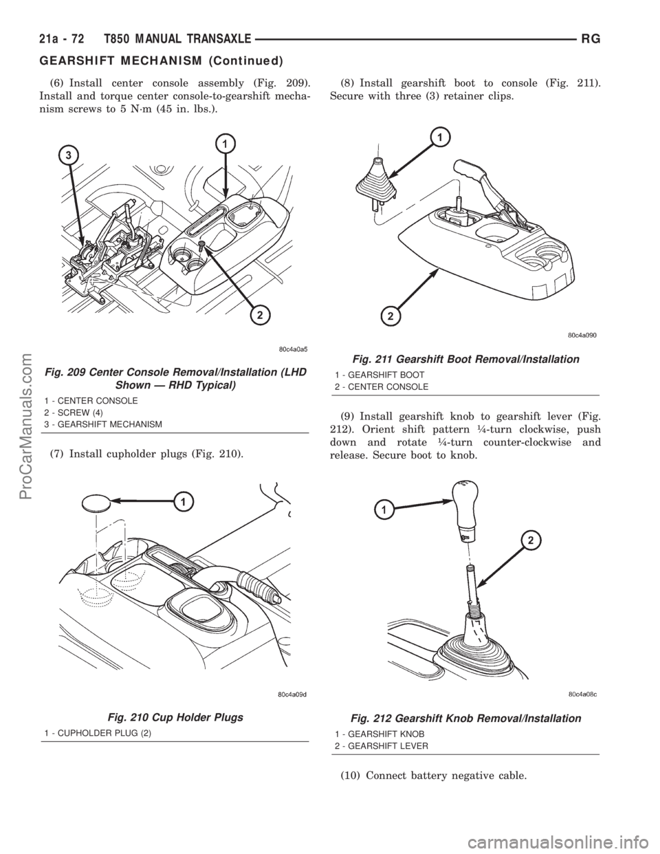
(6) Install center console assembly (Fig. 209).
Install and torque center console-to-gearshift mecha-
nism screws to 5 N´m (45 in. lbs.).
(7) Install cupholder plugs (Fig. 210).(8) Install gearshift boot to console (Fig. 211).
Secure with three (3) retainer clips.
(9) Install gearshift knob to gearshift lever (Fig.
212). Orient shift pattern ò-turn clockwise, push
down and rotate ò-turn counter-clockwise and
release. Secure boot to knob.
(10) Connect battery negative cable.
Fig. 209 Center Console Removal/Installation (LHD
Shown Ð RHD Typical)
1 - CENTER CONSOLE
2 - SCREW (4)
3 - GEARSHIFT MECHANISM
Fig. 210 Cup Holder Plugs
1 - CUPHOLDER PLUG (2)
Fig. 211 Gearshift Boot Removal/Installation
1 - GEARSHIFT BOOT
2 - CENTER CONSOLE
Fig. 212 Gearshift Knob Removal/Installation
1 - GEARSHIFT KNOB
2 - GEARSHIFT LEVER
21a - 72 T850 MANUAL TRANSAXLERG
GEARSHIFT MECHANISM (Continued)
ProCarManuals.com
Page 1872 of 2321
INPUT SHAFT
DESCRIPTION
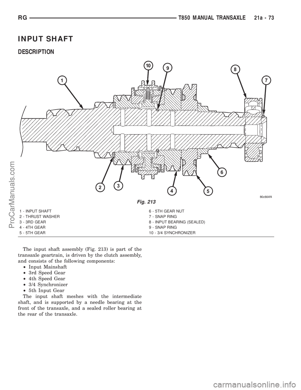
The input shaft assembly (Fig. 213) is part of the
transaxle geartrain, is driven by the clutch assembly,
and consists of the following components:
²Input Mainshaft
²3rd Speed Gear
²4th Speed Gear
²3/4 Synchronizer
²5th Input Gear
The input shaft meshes with the intermediate
shaft, and is supported by a needle bearing at the
front of the transaxle, and a sealed roller bearing at
the rear of the transaxle.
1 - INPUT SHAFT 6 - 5TH GEAR NUT
2 - THRUST WASHER 7 - SNAP RING
3 - 3RD GEAR 8 - INPUT BEARING (SEALED)
4 - 4TH GEAR 9 - SNAP RING
5 - 5TH GEAR 10 - 3/4 SYNCHRONIZER
Fig. 213
RGT850 MANUAL TRANSAXLE21a-73
ProCarManuals.com
Page 1873 of 2321
DISASSEMBLY
NOTE: When servicing the input shaft assembly, all
snap rings which are removed MUST be replaced
with new snap rings upon reassembly. The 5th gear
nut must be replaced also.
(1) Invert input shaft assembly and place in fix-
ture 8487.
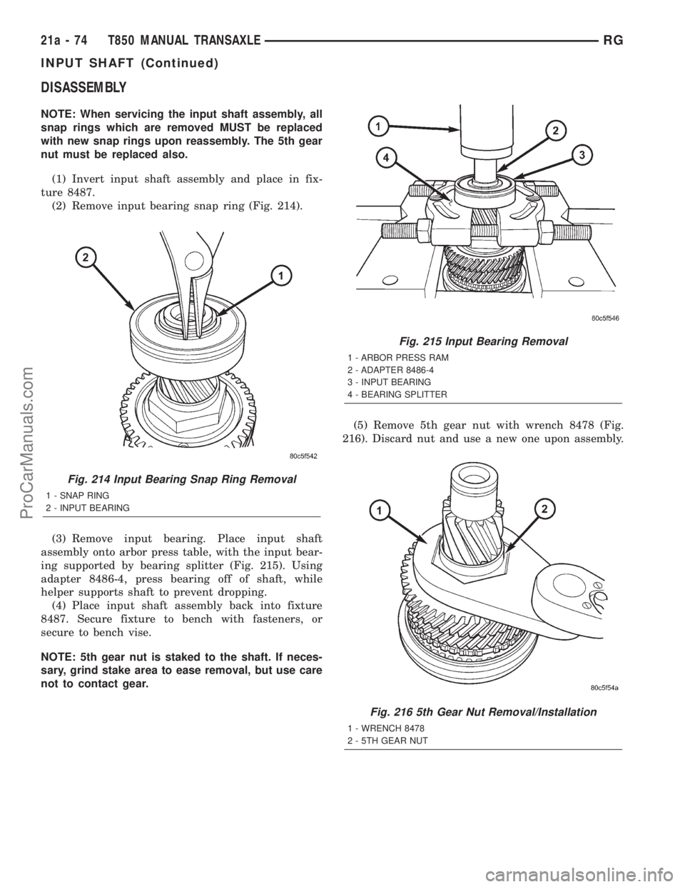
(2) Remove input bearing snap ring (Fig. 214).
(3) Remove input bearing. Place input shaft
assembly onto arbor press table, with the input bear-
ing supported by bearing splitter (Fig. 215). Using
adapter 8486-4, press bearing off of shaft, while
helper supports shaft to prevent dropping.
(4) Place input shaft assembly back into fixture
8487. Secure fixture to bench with fasteners, or
secure to bench vise.
NOTE: 5th gear nut is staked to the shaft. If neces-
sary, grind stake area to ease removal, but use care
not to contact gear.(5) Remove 5th gear nut with wrench 8478 (Fig.
216). Discard nut and use a new one upon assembly.
Fig. 214 Input Bearing Snap Ring Removal
1 - SNAP RING
2 - INPUT BEARING
Fig. 215 Input Bearing Removal
1 - ARBOR PRESS RAM
2 - ADAPTER 8486-4
3 - INPUT BEARING
4 - BEARING SPLITTER
Fig. 216 5th Gear Nut Removal/Installation
1 - WRENCH 8478
2 - 5TH GEAR NUT
21a - 74 T850 MANUAL TRANSAXLERG
INPUT SHAFT (Continued)
ProCarManuals.com
Page 1874 of 2321
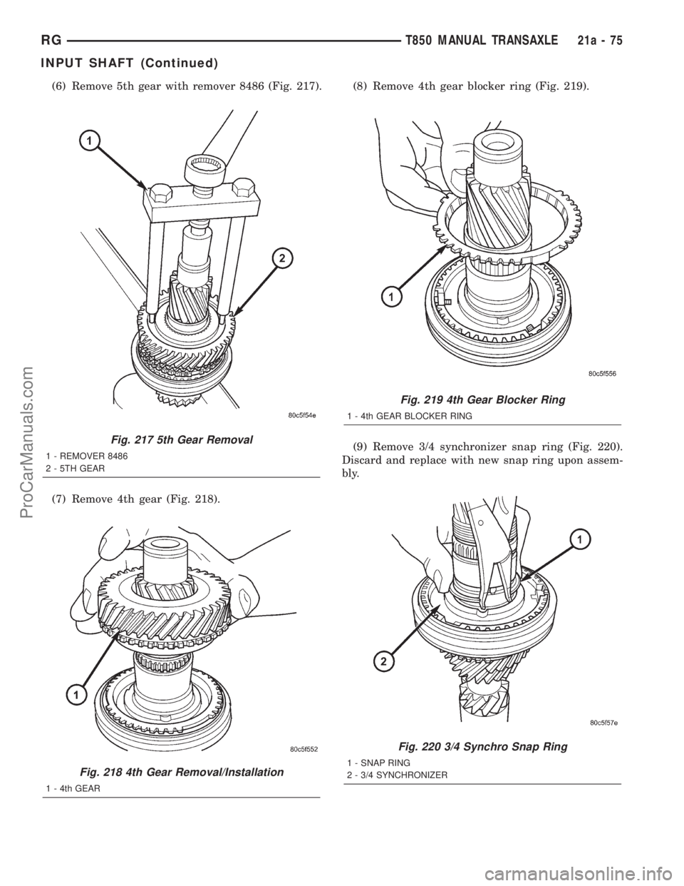
(6) Remove 5th gear with remover 8486 (Fig. 217).
(7) Remove 4th gear (Fig. 218).(8) Remove 4th gear blocker ring (Fig. 219).
(9) Remove 3/4 synchronizer snap ring (Fig. 220).
Discard and replace with new snap ring upon assem-
bly.
Fig. 217 5th Gear Removal
1 - REMOVER 8486
2 - 5TH GEAR
Fig. 218 4th Gear Removal/Installation
1 - 4th GEAR
Fig. 219 4th Gear Blocker Ring
1 - 4th GEAR BLOCKER RING
Fig. 220 3/4 Synchro Snap Ring
1 - SNAP RING
2 - 3/4 SYNCHRONIZER
RGT850 MANUAL TRANSAXLE21a-75
INPUT SHAFT (Continued)
ProCarManuals.com
Page 1875 of 2321
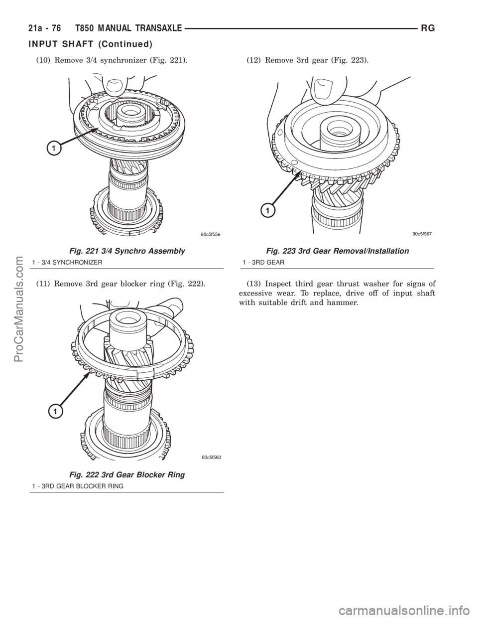
(10) Remove 3/4 synchronizer (Fig. 221).
(11) Remove 3rd gear blocker ring (Fig. 222).(12) Remove 3rd gear (Fig. 223).
(13) Inspect third gear thrust washer for signs of
excessive wear. To replace, drive off of input shaft
with suitable drift and hammer.
Fig. 221 3/4 Synchro Assembly
1 - 3/4 SYNCHRONIZER
Fig. 222 3rd Gear Blocker Ring
1 - 3RD GEAR BLOCKER RING
Fig. 223 3rd Gear Removal/Installation
1 - 3RD GEAR
21a - 76 T850 MANUAL TRANSAXLERG
INPUT SHAFT (Continued)
ProCarManuals.com
Page 1876 of 2321
ASSEMBLY
NOTE: When servicing the input shaft assembly, all
snap rings MUST be replaced with new ones upon
assembly. 5th gear nut must also be replaced.
NOTE: When installing 3/4 synchronizer hub to
shaft, make sure to align oil slots on synchronizer
hub face with oil hole in the shaft splined hub jour-
nal.
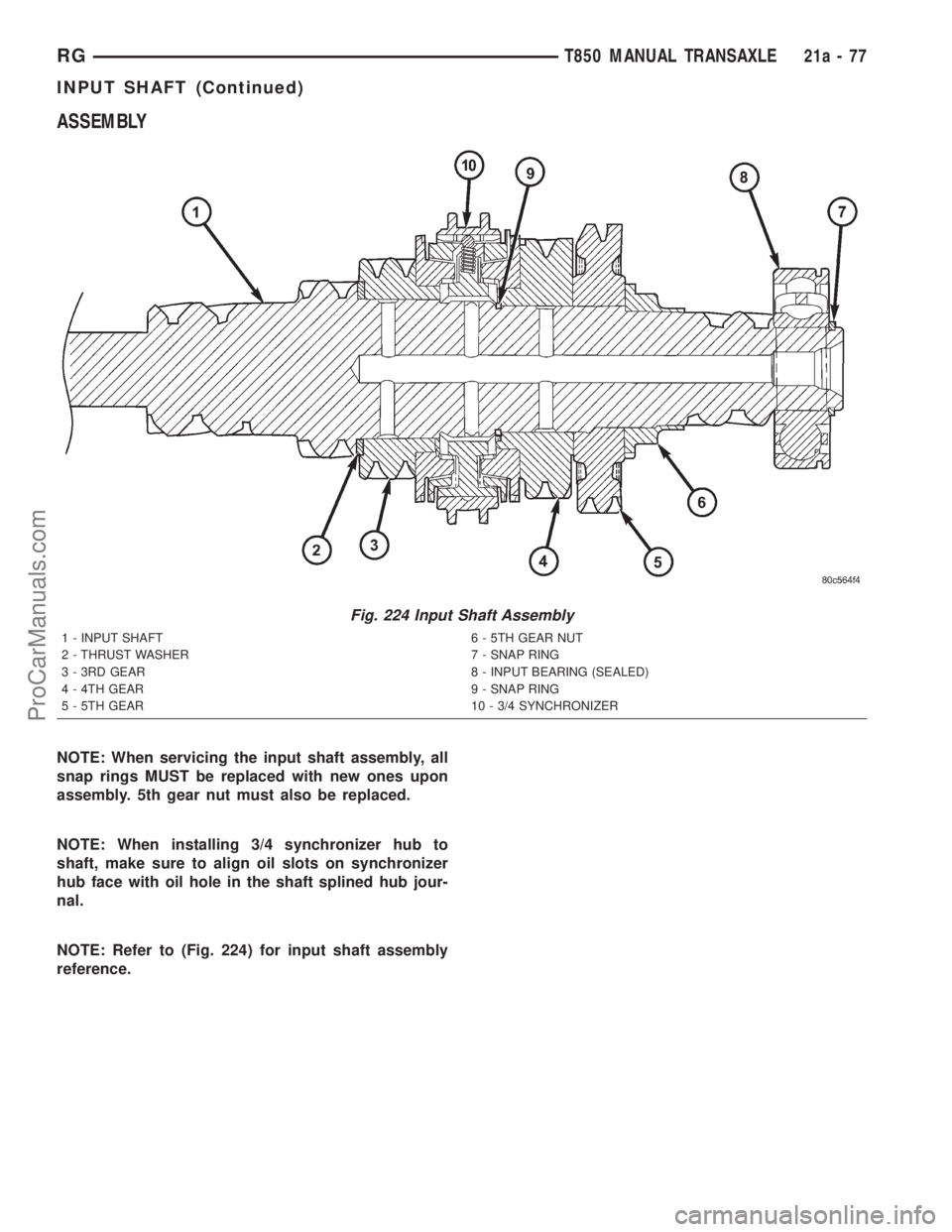
NOTE: Refer to (Fig. 224) for input shaft assembly
reference.
Fig. 224 Input Shaft Assembly
1 - INPUT SHAFT 6 - 5TH GEAR NUT
2 - THRUST WASHER 7 - SNAP RING
3 - 3RD GEAR 8 - INPUT BEARING (SEALED)
4 - 4TH GEAR 9 - SNAP RING
5 - 5TH GEAR 10 - 3/4 SYNCHRONIZER
RGT850 MANUAL TRANSAXLE21a-77
INPUT SHAFT (Continued)
ProCarManuals.com
Page 1877 of 2321
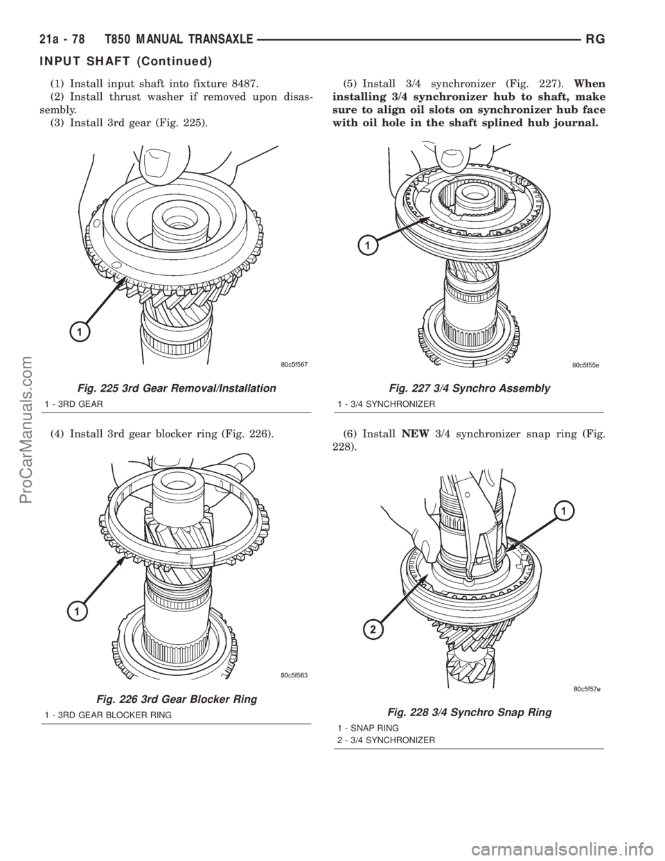
(1) Install input shaft into fixture 8487.
(2) Install thrust washer if removed upon disas-
sembly.
(3) Install 3rd gear (Fig. 225).
(4) Install 3rd gear blocker ring (Fig. 226).(5) Install 3/4 synchronizer (Fig. 227).When
installing 3/4 synchronizer hub to shaft, make
sure to align oil slots on synchronizer hub face
with oil hole in the shaft splined hub journal.
(6) InstallNEW3/4 synchronizer snap ring (Fig.
228).
Fig. 225 3rd Gear Removal/Installation
1 - 3RD GEAR
Fig. 226 3rd Gear Blocker Ring
1 - 3RD GEAR BLOCKER RING
Fig. 227 3/4 Synchro Assembly
1 - 3/4 SYNCHRONIZER
Fig. 228 3/4 Synchro Snap Ring
1 - SNAP RING
2 - 3/4 SYNCHRONIZER
21a - 78 T850 MANUAL TRANSAXLERG
INPUT SHAFT (Continued)
ProCarManuals.com
Page 1878 of 2321
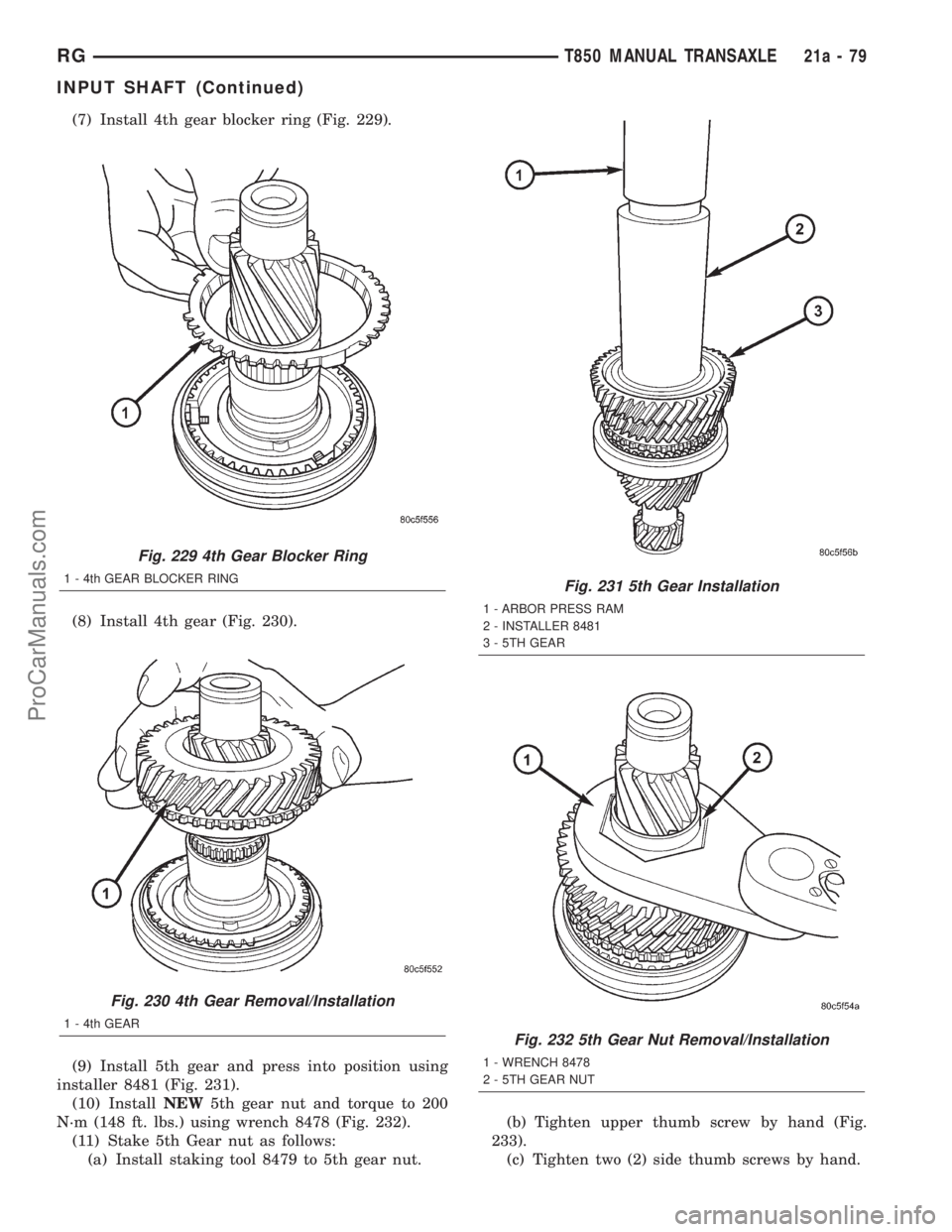
(7) Install 4th gear blocker ring (Fig. 229).
(8) Install 4th gear (Fig. 230).
(9) Install 5th gear and press into position using
installer 8481 (Fig. 231).
(10) InstallNEW5th gear nut and torque to 200
N´m (148 ft. lbs.) using wrench 8478 (Fig. 232).
(11) Stake 5th Gear nut as follows:
(a) Install staking tool 8479 to 5th gear nut.(b) Tighten upper thumb screw by hand (Fig.
233).
(c) Tighten two (2) side thumb screws by hand.
Fig. 229 4th Gear Blocker Ring
1 - 4th GEAR BLOCKER RING
Fig. 230 4th Gear Removal/Installation
1 - 4th GEAR
Fig. 231 5th Gear Installation
1 - ARBOR PRESS RAM
2 - INSTALLER 8481
3 - 5TH GEAR
Fig. 232 5th Gear Nut Removal/Installation
1 - WRENCH 8478
2 - 5TH GEAR NUT
RGT850 MANUAL TRANSAXLE21a-79
INPUT SHAFT (Continued)
ProCarManuals.com
Page 1879 of 2321
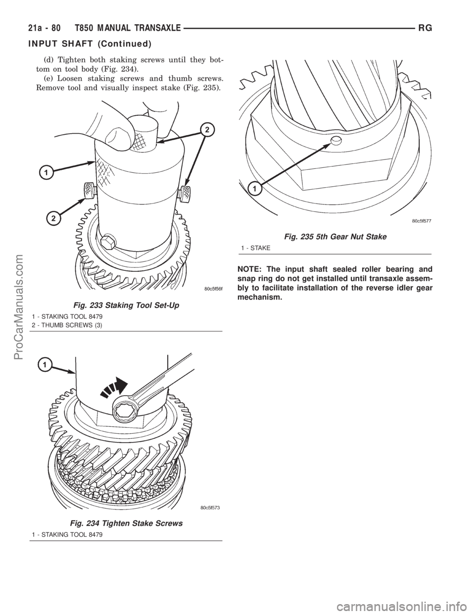
(d) Tighten both staking screws until they bot-
tom on tool body (Fig. 234).
(e) Loosen staking screws and thumb screws.
Remove tool and visually inspect stake (Fig. 235).
NOTE: The input shaft sealed roller bearing and
snap ring do not get installed until transaxle assem-
bly to facilitate installation of the reverse idler gear
mechanism.
Fig. 233 Staking Tool Set-Up
1 - STAKING TOOL 8479
2 - THUMB SCREWS (3)
Fig. 234 Tighten Stake Screws
1 - STAKING TOOL 8479
Fig. 235 5th Gear Nut Stake
1-STAKE
21a - 80 T850 MANUAL TRANSAXLERG
INPUT SHAFT (Continued)
ProCarManuals.com
Page 1880 of 2321
INTERMEDIATE SHAFT
DESCRIPTION
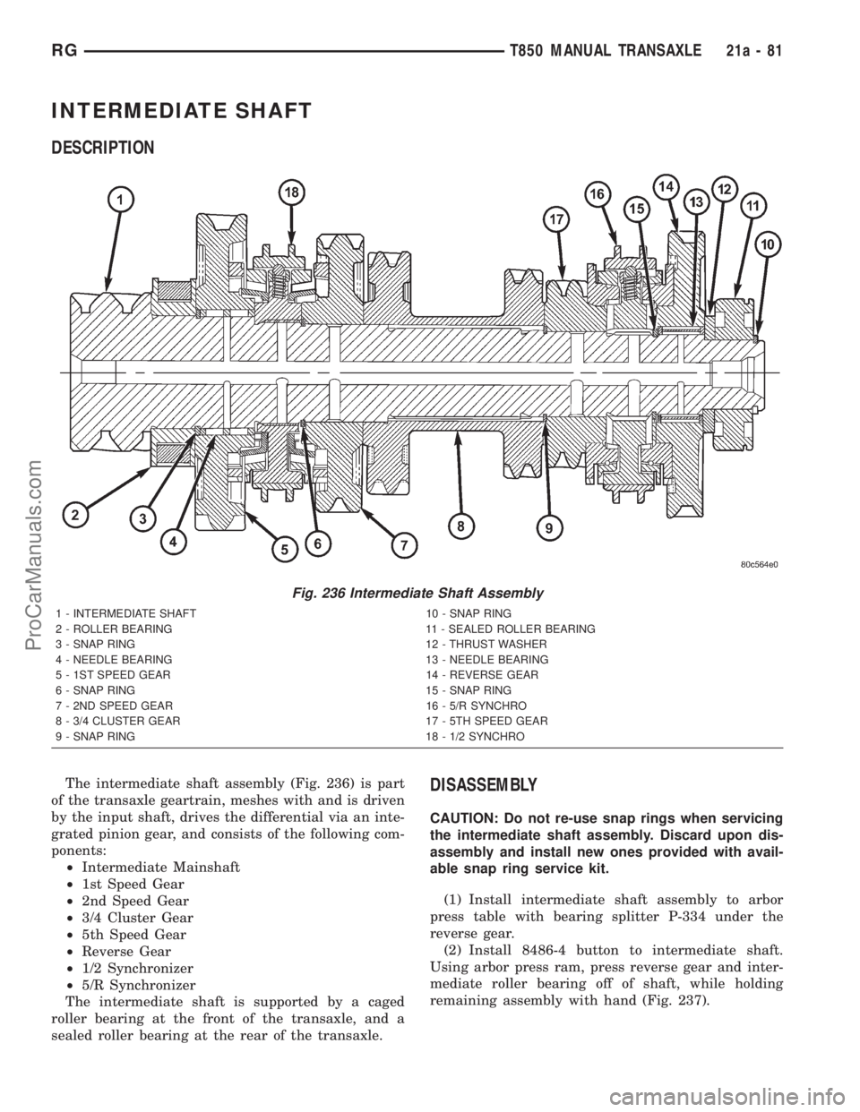
The intermediate shaft assembly (Fig. 236) is part
of the transaxle geartrain, meshes with and is driven
by the input shaft, drives the differential via an inte-
grated pinion gear, and consists of the following com-
ponents:
²Intermediate Mainshaft
²1st Speed Gear
²2nd Speed Gear
²3/4 Cluster Gear
²5th Speed Gear
²Reverse Gear
²1/2 Synchronizer
²5/R Synchronizer
The intermediate shaft is supported by a caged
roller bearing at the front of the transaxle, and a
sealed roller bearing at the rear of the transaxle.DISASSEMBLY
CAUTION: Do not re-use snap rings when servicing
the intermediate shaft assembly. Discard upon dis-
assembly and install new ones provided with avail-
able snap ring service kit.
(1) Install intermediate shaft assembly to arbor
press table with bearing splitter P-334 under the
reverse gear.
(2) Install 8486-4 button to intermediate shaft.
Using arbor press ram, press reverse gear and inter-
mediate roller bearing off of shaft, while holding
remaining assembly with hand (Fig. 237).
Fig. 236 Intermediate Shaft Assembly
1 - INTERMEDIATE SHAFT 10 - SNAP RING
2 - ROLLER BEARING 11 - SEALED ROLLER BEARING
3 - SNAP RING 12 - THRUST WASHER
4 - NEEDLE BEARING 13 - NEEDLE BEARING
5 - 1ST SPEED GEAR 14 - REVERSE GEAR
6 - SNAP RING 15 - SNAP RING
7 - 2ND SPEED GEAR 16 - 5/R SYNCHRO
8 - 3/4 CLUSTER GEAR 17 - 5TH SPEED GEAR
9 - SNAP RING 18 - 1/2 SYNCHRO
RGT850 MANUAL TRANSAXLE21a-81
ProCarManuals.com