sensor DODGE TOWN AND COUNTRY 2002 Service Manual
[x] Cancel search | Manufacturer: DODGE, Model Year: 2002, Model line: TOWN AND COUNTRY, Model: DODGE TOWN AND COUNTRY 2002Pages: 2399, PDF Size: 57.96 MB
Page 477 of 2399
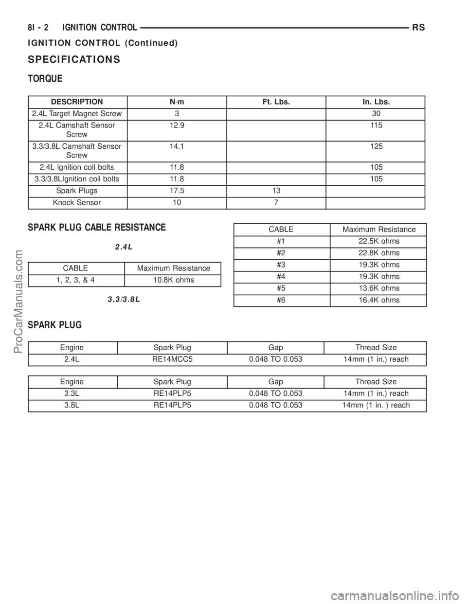
SPECIFICATIONS
TORQUE
DESCRIPTION N´m Ft. Lbs. In. Lbs.
2.4L Target Magnet Screw 3 30
2.4L Camshaft Sensor
Screw12.9 115
3.3/3.8L Camshaft Sensor
Screw14.1 125
2.4L Ignition coil bolts 11.8 105
3.3/3.8LIgnition coil bolts 11.8 105
Spark Plugs 17.5 13
Knock Sensor 10 7
SPARK PLUG CABLE RESISTANCE
2.4L
CABLE Maximum Resistance
1, 2, 3, & 4 10.8K ohms
3.3/3.8L
CABLE Maximum Resistance
#1 22.5K ohms
#2 22.8K ohms
#3 19.3K ohms
#4 19.3K ohms
#5 13.6K ohms
#6 16.4K ohms
SPARK PLUG
Engine Spark Plug Gap Thread Size
2.4L RE14MCC5 0.048 TO 0.053 14mm (1 in.) reach
Engine Spark Plug Gap Thread Size
3.3L RE14PLP5 0.048 TO 0.053 14mm (1 in.) reach
3.8L RE14PLP5 0.048 TO 0.053 14mm (1 in. ) reach
8I - 2 IGNITION CONTROLRS
IGNITION CONTROL (Continued)
ProCarManuals.com
Page 478 of 2399
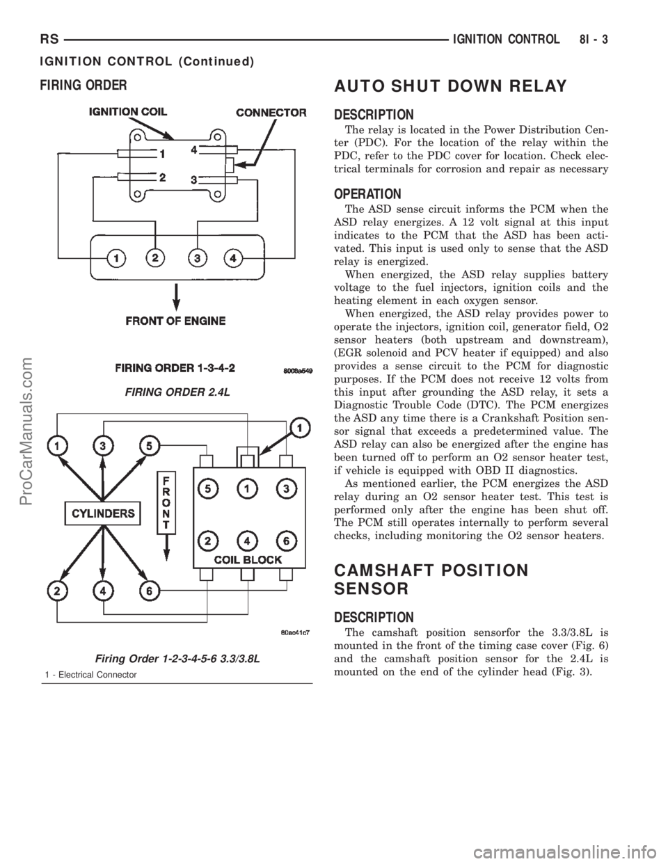
FIRING ORDERAUTO SHUT DOWN RELAY
DESCRIPTION
The relay is located in the Power Distribution Cen-
ter (PDC). For the location of the relay within the
PDC, refer to the PDC cover for location. Check elec-
trical terminals for corrosion and repair as necessary
OPERATION
The ASD sense circuit informs the PCM when the
ASD relay energizes. A 12 volt signal at this input
indicates to the PCM that the ASD has been acti-
vated. This input is used only to sense that the ASD
relay is energized.
When energized, the ASD relay supplies battery
voltage to the fuel injectors, ignition coils and the
heating element in each oxygen sensor.
When energized, the ASD relay provides power to
operate the injectors, ignition coil, generator field, O2
sensor heaters (both upstream and downstream),
(EGR solenoid and PCV heater if equipped) and also
provides a sense circuit to the PCM for diagnostic
purposes. If the PCM does not receive 12 volts from
this input after grounding the ASD relay, it sets a
Diagnostic Trouble Code (DTC). The PCM energizes
the ASD any time there is a Crankshaft Position sen-
sor signal that exceeds a predetermined value. The
ASD relay can also be energized after the engine has
been turned off to perform an O2 sensor heater test,
if vehicle is equipped with OBD II diagnostics.
As mentioned earlier, the PCM energizes the ASD
relay during an O2 sensor heater test. This test is
performed only after the engine has been shut off.
The PCM still operates internally to perform several
checks, including monitoring the O2 sensor heaters.
CAMSHAFT POSITION
SENSOR
DESCRIPTION
The camshaft position sensorfor the 3.3/3.8L is
mounted in the front of the timing case cover (Fig. 6)
and the camshaft position sensor for the 2.4L is
mounted on the end of the cylinder head (Fig. 3).
FIRING ORDER 2.4L
Firing Order 1-2-3-4-5-6 3.3/3.8L
1 - Electrical Connector
RSIGNITION CONTROL8I-3
IGNITION CONTROL (Continued)
ProCarManuals.com
Page 479 of 2399

OPERATION
The camshaft position sensor provides cylinder
identification to the Powertrain Control Module
(PCM) (Fig. 1). The sensor generates pulses as
groups of notches on the camshaft sprocket pass
underneath it (Fig. 2). The PCM keeps track of
crankshaft rotation and identifies each cylinder by
the pulses generated by the notches on the camshaft
sprocket. Four crankshaft pulses follow each group of
camshaft pulses.
When the PCM receives 2 cam pulses followed by
the long flat spot on the camshaft sprocket, it knows
that the crankshaft timing marks for cylinder 1 are
next (on driveplate). When the PCM receives one
camshaft pulse after the long flat spot on the
sprocket, cylinder number 2 crankshaft timing marks
are next. After 3 camshaft pulses, the PCM knows
cylinder 4 crankshaft timing marks follow. One cam-
shaft pulse after the 3 pulses indicates cylinder 5.
The 2 camshaft pulses after cylinder 5 signals cylin-
der 6 (Fig. 2). The PCM can synchronize on cylinders
1or4.
When metal aligns with the sensor, voltage goes
low (less than 0.3 volts). When a notch aligns with
the sensor, voltage switches high (5.0 volts). As a
group of notches pass under the sensor, the voltage
switches from low (metal) to high (notch) then back
to low. The number of notches determine the amount
of pulses. If available, an oscilloscope can display the
square wave patterns of each timing event.
Top Dead Center (TDC) does not occur when
notches on the camshaft sprocket pass below the cyl-
inder. TDC occurs after the camshaft pulse (or
pulses) and after the 4 crankshaft pulses associatedwith the particular cylinder. The arrows and cylinder
call outs on (Fig. 2) represent which cylinder the flat
spot and notches identify, they do not indicate TDC
position.
REMOVAL
REMOVAL - 2.4L
The camshaft position sensor is mounted to the
rear of the cylinder head.
(1) Remove the negative battery cable.
(2) Disconnect electrical connectors from the cam-
shaft position sensor (Fig. 3).
(3) Remove camshaft position sensor mounting
screws. Remove sensor.
(4) Loosen screw attaching target magnet to rear
of camshaft and remove magnet (Fig. 4).
REMOVAL - 3.3/3.8L
(1) Disconnect the negative battery cable.
(2) Remove the air box cover and inlet tube (Fig.
5).
(3) Disconnect camshaft position sensor electrical
connector from the wiring harness connector (Fig. 6).
(4) Remove bolt holding sensor.
(5) Rotate sensor away from block.
Fig. 1 Camshaft Position Sensor
1 - ELECTRICAL CONNECTOR
2 - O-RING
3 - PAPER SPACER
Fig. 2 Camshaft Sprocket
1 - CAMSHAFT SPROCKET
2 - CYL #6
3 - CYL #5
4 - CYL #4
5 - CYL #3
6 - CYL #2
7 - CYL #1
8I - 4 IGNITION CONTROLRS
CAMSHAFT POSITION SENSOR (Continued)
ProCarManuals.com
Page 480 of 2399
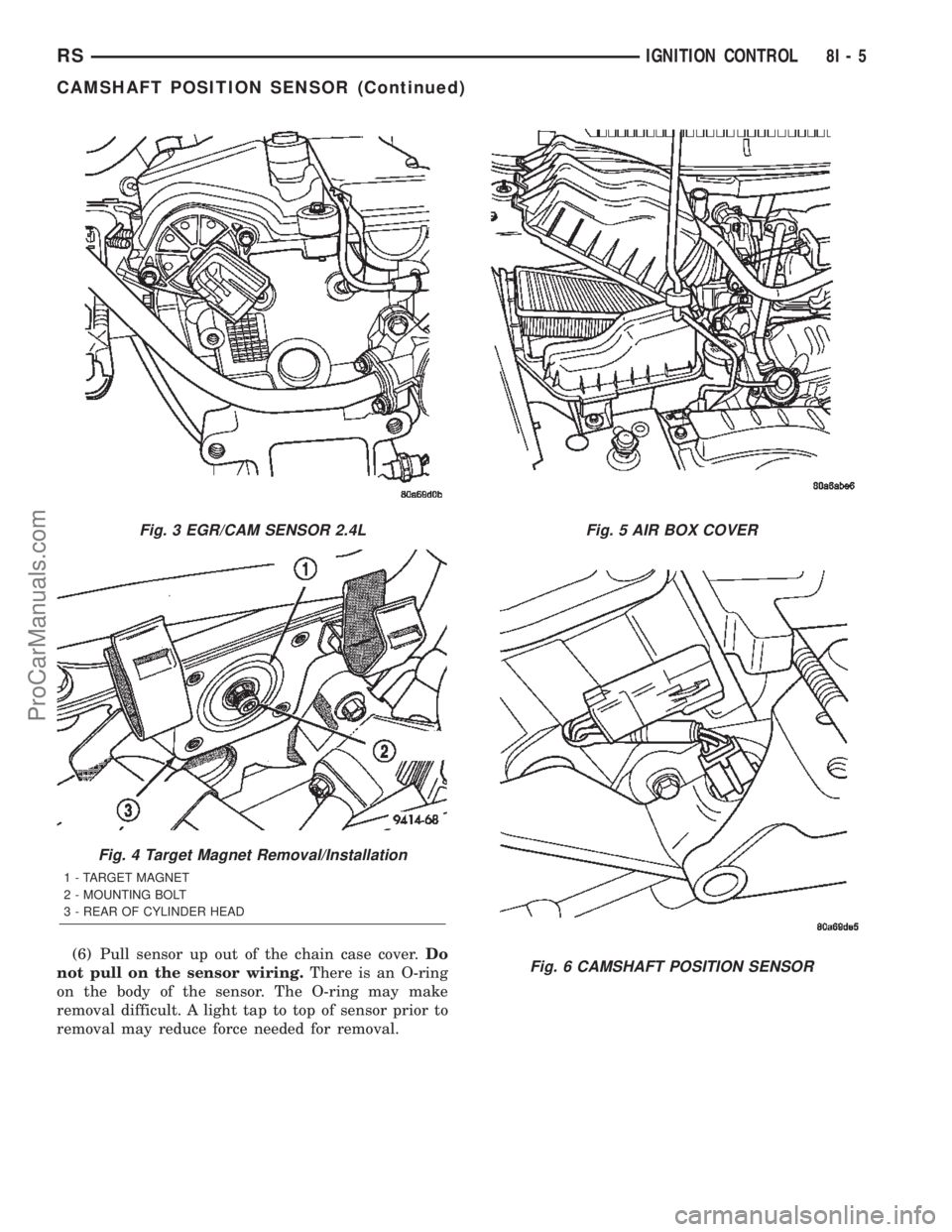
(6) Pull sensor up out of the chain case cover.Do
not pull on the sensor wiring.There is an O-ring
on the body of the sensor. The O-ring may make
removal difficult. A light tap to top of sensor prior to
removal may reduce force needed for removal.
Fig. 3 EGR/CAM SENSOR 2.4L
Fig. 4 Target Magnet Removal/Installation
1 - TARGET MAGNET
2 - MOUNTING BOLT
3 - REAR OF CYLINDER HEAD
Fig. 5 AIR BOX COVER
Fig. 6 CAMSHAFT POSITION SENSOR
RSIGNITION CONTROL8I-5
CAMSHAFT POSITION SENSOR (Continued)
ProCarManuals.com
Page 481 of 2399
INSTALLATION
INSTALLATION - 2.4L
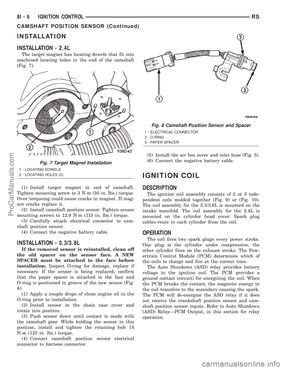
The target magnet has locating dowels that fit into
machined locating holes in the end of the camshaft
(Fig. 7).
(1) Install target magnet in end of camshaft.
Tighten mounting screw to 3 N´m (30 in. lbs.) torque.
Over torqueing could cause cracks in magnet. If mag-
net cracks replace it.
(2) Install camshaft position sensor. Tighten sensor
mounting screws to 12.9 N´m (115 in. lbs.) torque.
(3) Carefully attach electrical connector to cam-
shaft position sensor.
(4) Connect the negative battery cable.
INSTALLATION - 3.3/3.8L
If the removed sensor is reinstalled, clean off
the old spacer on the sensor face. A NEW
SPACER must be attached to the face before
installation.Inspect O-ring for damage, replace if
necessary. If the sensor is being replaced, confirm
that the paper spacer is attached to the face and
O-ring is positioned in groove of the new sensor (Fig.
8).
(1) Apply a couple drops of clean engine oil to the
O-ring prior to installation.
(2) Install sensor in the chain case cover and
rotate into position.
(3) Push sensor down until contact is made with
the camshaft gear. While holding the sensor in this
position, install and tighten the retaining bolt 14
N´m (125 in. lbs.) torque.
(4) Connect camshaft position sensor electrical
connector to harness connector.(5) Install the air box cover and inlet hose (Fig. 5).
(6) Connect the negative battery cable.
IGNITION COIL
DESCRIPTION
The ignition coil assembly consists of 2 or 3 inde-
pendent coils molded together (Fig. 9) or (Fig. 10).
The coil assembly for the 3.3/3.8L is mounted on the
intake manifold. The coil assembly for the 2.4L is
mounted on the cylinder head cover. Spark plug
cables route to each cylinder from the coil.
OPERATION
The coil fires two spark plugs every power stroke.
One plug is the cylinder under compression, the
other cylinder fires on the exhaust stroke. The Pow-
ertrain Control Module (PCM) determines which of
the coils to charge and fire at the correct time.
The Auto Shutdown (ASD) relay provides battery
voltage to the ignition coil. The PCM provides a
ground contact (circuit) for energizing the coil. When
the PCM breaks the contact, the magnetic energy in
the coil transfers to the secondary causing the spark.
The PCM will de-energize the ASD relay if it does
not receive the crankshaft position sensor and cam-
shaft position sensor inputs. Refer to Auto Shutdown
(ASD) RelayÐPCM Output, in this section for relay
operation.
Fig. 7 Target Magnet Installation
1 - LOCATING DOWELS
2 - LOCATING HOLES (2)
Fig. 8 Camshaft Position Sensor and Spacer
1 - ELECTRICAL CONNECTOR
2 - O-RING
3 - PAPER SPACER
8I - 6 IGNITION CONTROLRS
CAMSHAFT POSITION SENSOR (Continued)
ProCarManuals.com
Page 483 of 2399
INSTALLATION - 3.3/3.8L
(1) Install coil over studs on bracket.
(2) Install 2 bolts to ignition coil.
(3) Install 2 nuts to the ignition coil studs. Tighten
nuts and bolts.
(4) Connect the electrical connector to the ignition
coil.
(5) Install the ignition cables to the ignition coil.
(6) Reposition the Power steering reservoir. Slide
bracket over the mounting stud (Fig. 11).
(7) Install 2 bolts to the Power steering reservoir
to intake manifold.
(8) Tighten the lower nut to stud on ignition coil
bracket.
(9) Install the throttle and speed control cables to
clip.
(10) Connect the negative battery cable.
KNOCK SENSOR
DESCRIPTION
The knock sensor threads into the cylinder block.
The knock sensor is designed to detect engine vibra-
tion that is caused by detonation.
OPERATION
When the knock sensor detects a knock in one of
the cylinders, it sends an input signal to the PCM. In
response, the PCM retards ignition timing for all cyl-
inders by a scheduled amount.
Knock sensors contain a piezoelectric material
which constantly vibrates and sends an input voltage
(signal) to the PCM while the engine operates. As the
intensity of the crystal's vibration increases, the
knock sensor output voltage also increases.
The voltage signal produced by the knock sensor
increases with the amplitude of vibration. The PCM
receives as an input the knock sensor voltage signal.
If the signal rises above a predetermined level, the
PCM will store that value in memory and retard
ignition timing to reduce engine knock. If the knock
sensor voltage exceeds a preset value, the PCM
retards ignition timing for all cylinders. It is not a
selective cylinder retard.
The PCM ignores knock sensor input during engine
idle conditions. Once the engine speed exceeds a
specified value, knock retard is allowed.
Knock retard uses its own short term and long
term memory program.
Long term memory stores previous detonation
information in its battery-backed RAM. The maxi-
mum authority that long term memory has over tim-
ing retard can be calibrated.
Short term memory is allowed to retard timing up
to a preset amount under all operating conditions (aslong as rpm is above the minimum rpm) except WOT.
The PCM, using short term memory, can respond
quickly to retard timing when engine knock is
detected. Short term memory is lost any time the
ignition key is turned off.
NOTE: Over or under tightening affects knock sen-
sor performance, possibly causing improper spark
control.
REMOVAL
REMOVAL - 2.4L
The knock sensor threads into the side of the cyl-
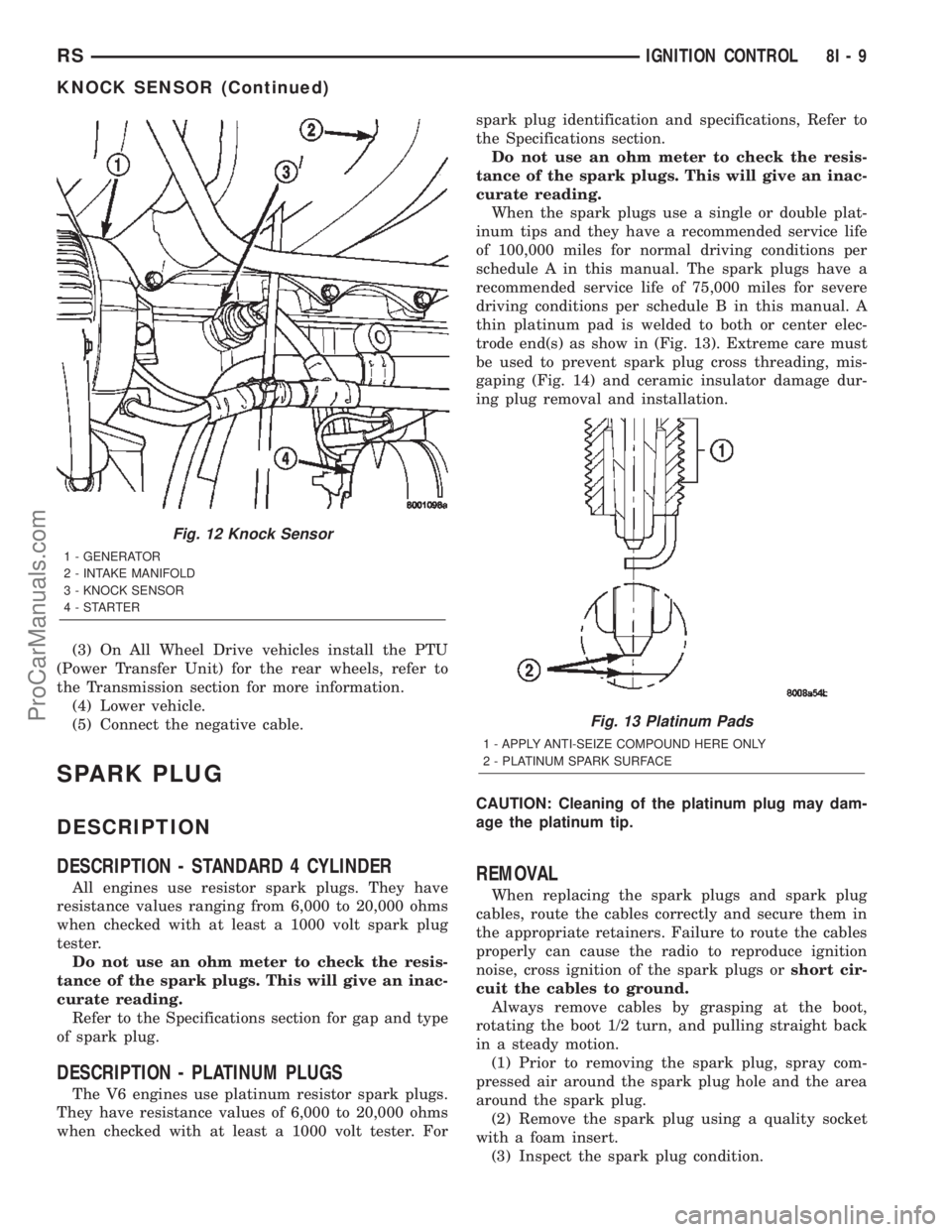
inder block in front of the starter (Fig. 12).
(1) Disconnect electrical connector from knock sen-
sor.
(2) Use a crow foot socket to remove the knock
sensors.
REMOVAL - 3.8L
The knock sensor threads into the side of the cyl-
inder block in the rear.
(1) Disconnect the negative battery cable.
(2) Raise vehicle and support.
(3) On All Wheel Drive vehicles remove the PTU
(Power Transfer Unit), refer to the Transmission sec-
tion for more information.
(4) Disconnect electrical connector from knock sen-
sor.
(5) Use a crow foot socket to remove the knock
sensor.
INSTALLATION
INSTALLATION - 2.4L
The knock sensor threads into the side of the cyl-
inder block in front of the starter (Fig. 12).
(1) Install knock sensor. Tighten knock sensor to
10 N´m (7 ft. lbs.) torque.Over or under tighten-
ing effects knock sensor performance, possibly
causing improper spark control.
(2) Attach electrical connector to knock sensor.
INSTALLATION - 3.8L
The knock sensor threads into the side of the cyl-
inder block in the rear.
(1) Install knock sensor. Tighten knock sensor to
10 N´m (7 ft. lbs.) torque.Over or under tighten-
ing effects knock sensor performance, possibly
causing improper spark control.
(2) Attach electrical connector to knock sensor.
8I - 8 IGNITION CONTROLRS
IGNITION COIL (Continued)
ProCarManuals.com
Page 484 of 2399
(3) On All Wheel Drive vehicles install the PTU
(Power Transfer Unit) for the rear wheels, refer to
the Transmission section for more information.
(4) Lower vehicle.
(5) Connect the negative cable.
SPARK PLUG
DESCRIPTION
DESCRIPTION - STANDARD 4 CYLINDER
All engines use resistor spark plugs. They have
resistance values ranging from 6,000 to 20,000 ohms
when checked with at least a 1000 volt spark plug
tester.
Do not use an ohm meter to check the resis-
tance of the spark plugs. This will give an inac-
curate reading.
Refer to the Specifications section for gap and type
of spark plug.
DESCRIPTION - PLATINUM PLUGS
The V6 engines use platinum resistor spark plugs.
They have resistance values of 6,000 to 20,000 ohms
when checked with at least a 1000 volt tester. Forspark plug identification and specifications, Refer to
the Specifications section.
Do not use an ohm meter to check the resis-
tance of the spark plugs. This will give an inac-
curate reading.
When the spark plugs use a single or double plat-
inum tips and they have a recommended service life
of 100,000 miles for normal driving conditions per
schedule A in this manual. The spark plugs have a
recommended service life of 75,000 miles for severe
driving conditions per schedule B in this manual. A
thin platinum pad is welded to both or center elec-
trode end(s) as show in (Fig. 13). Extreme care must
be used to prevent spark plug cross threading, mis-
gaping (Fig. 14) and ceramic insulator damage dur-
ing plug removal and installation.
CAUTION: Cleaning of the platinum plug may dam-
age the platinum tip.
REMOVAL
When replacing the spark plugs and spark plug
cables, route the cables correctly and secure them in
the appropriate retainers. Failure to route the cables
properly can cause the radio to reproduce ignition
noise, cross ignition of the spark plugs orshort cir-
cuit the cables to ground.
Always remove cables by grasping at the boot,
rotating the boot 1/2 turn, and pulling straight back
in a steady motion.
(1) Prior to removing the spark plug, spray com-
pressed air around the spark plug hole and the area
around the spark plug.
(2) Remove the spark plug using a quality socket
with a foam insert.
(3) Inspect the spark plug condition.
Fig. 12 Knock Sensor
1 - GENERATOR
2 - INTAKE MANIFOLD
3 - KNOCK SENSOR
4-STARTER
Fig. 13 Platinum Pads
1 - APPLY ANTI-SEIZE COMPOUND HERE ONLY
2 - PLATINUM SPARK SURFACE
RSIGNITION CONTROL8I-9
KNOCK SENSOR (Continued)
ProCarManuals.com
Page 486 of 2399
IGNITION CONTROL
TABLE OF CONTENTS
page page
GLOW PLUG
DESCRIPTION..........................1
OPERATION............................1
GLOW PLUG RELAY
DESCRIPTION..........................1
OPERATION............................1CAMSHAFT POSITION SENSOR
DESCRIPTION..........................2
OPERATION............................2
REMOVAL.............................2
INSTALLATION..........................2
GLOW PLUG
DESCRIPTION
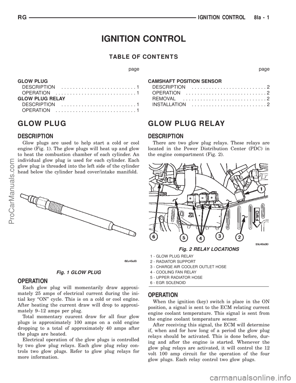
Glow plugs are used to help start a cold or cool
engine (Fig. 1). The glow plugs will heat up and glow
to heat the combustion chamber of each cylinder. An
individual glow plug is used for each cylinder. Each
glow plug is threaded into the left side of the cylinder
head below the cylinder head cover/intake manifold.
OPERATION
Each glow plug will momentarily draw approxi-
mately 25 amps of electrical current during the ini-
tial key ªONº cycle. This is on a cold or cool engine.
After heating the current draw will drop to approxi-
mately 9±12 amps per plug.
Total momentary cuurent draw for all four glow
plugs is approximately 100 amps on a cold engine
dropping to a total of approximately 40 amps after
the plugs are heated.
Electrical operation of the glow plugs is controlled
by two glow plug relays. Each glow plug relay con-
trols two glow plugs. Refer to glow plug relays for
more information.
GLOW PLUG RELAY
DESCRIPTION
There are two glow plug relays. These relays are
located in the Power Distribution Center (PDC) in
the engine compartment (Fig. 2).
OPERATION
When the ignition (key) switch is place in the ON
position, a signal is sent to the ECM relating current
engine coolant temperature. This signal is sent from
the engine coolant temperature sensor.
After receiving this signal, the ECM will determine
if, when and for how long of a period the glow plug
relays should be activated. This is done before, dur-
ing and after the engine is started. Whenever the
glow plug relays are activated, it will control the 12
volt 100 amp circuit for the operation of the four
glow plugs. Each relay control two glow plugs.
Fig. 1 GLOW PLUG
Fig. 2 RELAY LOCATIONS
1 - GLOW PLUG RELAY
2 - RADIATOR SUPPORT
3 - CHARGE AIR COOLER OUTLET HOSE
4 - COOLING FAN RELAY
5 - UPPER RADIATOR HOSE
6 - EGR SOLENOID
RGIGNITION CONTROL8Ia-1
ProCarManuals.com
Page 487 of 2399
The Glow Plug lamp is tied to this circuit. Lamp
operation is also controlled by the ECM.
With a cold engine, the glow plug relays and glow
plugs may be activated for a maximum time of 200
seconds. Refer to the following Glow Plug Control
chart for a temperature/time comparison of the glow
plug relay operation.
In this chart, Pre-Heat and Post-Heat times are
mentioned. Pre-Heat is the amount of time the glow
plug relay control circuit is activated when the igni-
tion (key) is switched ON, without the engine run-
ning. Post-Heat is the amount of time the glow plug
relay control circuit is activated after the engine is
operated. The Glow Plug lamp will not be activated
during the post-heat cycle.
Engine
Coolant
Temperature
9Key ON9Wait-To
Start Lamp
9ON9
(Seconds)Pre-Heat
Cycle
(Glow
Plugs On
Seconds)Post-Heat
Cycle
(Seconds)
-30C 20 SEC. 35 SEC. 200 SEC.
-10C 8 SEC. 23 SEC. 180 SEC.
+10C 6 SEC. 21 SEC. 160 SEC.
+30C 5 SEC. 20 SEC. 140 SEC.
+40C 4 SEC. 19 SEC. 70 SEC.
+70C 1 SEC. 16 SEC. 20 SEC.
CAMSHAFT POSITION
SENSOR
DESCRIPTION
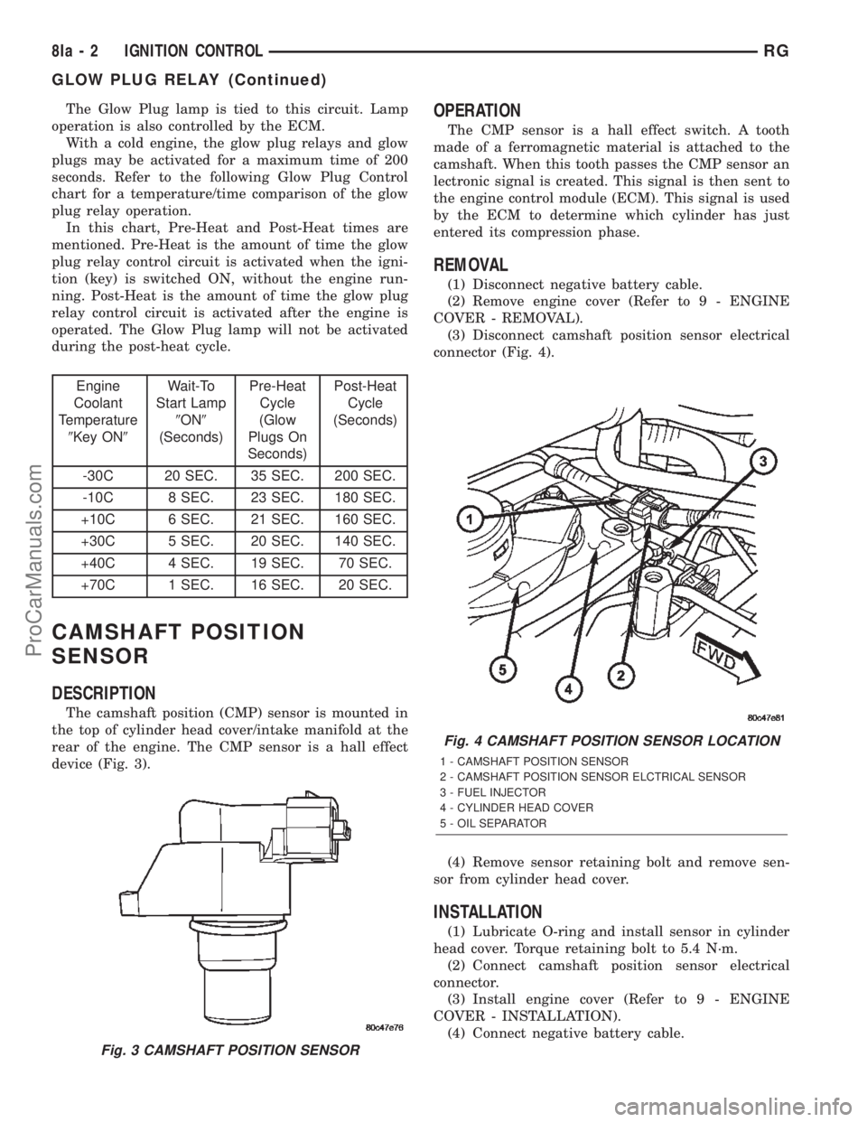
The camshaft position (CMP) sensor is mounted in
the top of cylinder head cover/intake manifold at the
rear of the engine. The CMP sensor is a hall effect
device (Fig. 3).
OPERATION
The CMP sensor is a hall effect switch. A tooth
made of a ferromagnetic material is attached to the
camshaft. When this tooth passes the CMP sensor an
lectronic signal is created. This signal is then sent to
the engine control module (ECM). This signal is used
by the ECM to determine which cylinder has just
entered its compression phase.
REMOVAL
(1) Disconnect negative battery cable.
(2) Remove engine cover (Refer to 9 - ENGINE
COVER - REMOVAL).
(3) Disconnect camshaft position sensor electrical
connector (Fig. 4).
(4) Remove sensor retaining bolt and remove sen-
sor from cylinder head cover.
INSTALLATION
(1) Lubricate O-ring and install sensor in cylinder
head cover. Torque retaining bolt to 5.4 N´m.
(2) Connect camshaft position sensor electrical
connector.
(3) Install engine cover (Refer to 9 - ENGINE
COVER - INSTALLATION).
(4) Connect negative battery cable.
Fig. 3 CAMSHAFT POSITION SENSOR
Fig. 4 CAMSHAFT POSITION SENSOR LOCATION
1 - CAMSHAFT POSITION SENSOR
2 - CAMSHAFT POSITION SENSOR ELCTRICAL SENSOR
3 - FUEL INJECTOR
4 - CYLINDER HEAD COVER
5 - OIL SEPARATOR
8Ia - 2 IGNITION CONTROLRG
GLOW PLUG RELAY (Continued)
ProCarManuals.com
Page 488 of 2399
INSTRUMENT CLUSTER
TABLE OF CONTENTS
page page
INSTRUMENT CLUSTER
DESCRIPTION..........................1
OPERATION............................1
DIAGNOSIS AND TESTING
DIAGNOSIS AND TESTING - SELF-
DIAGNOSTICS.........................2
DIAGNOSIS AND TESTING - CLUSTER
DIAGNOSIS...........................2
REMOVAL.............................11
INSTALLATION.........................12CLUSTER LENS
REMOVAL.............................12
INSTALLATION.........................12
MECHANICAL TRANSMISSION RANGE
INDICATOR
REMOVAL.............................12
INSTALLATION.........................12
RED BRAKE WARNING INDICATOR
DESCRIPTION.........................13
OPERATION...........................13
INSTRUMENT CLUSTER
DESCRIPTION
The instrumentation gauges are contained in a
subdial assembly within the instrument cluster. The
individual gauges are not serviceable. If one of the
cluster gauges becomes faulty, the entire cluster
would require replacement.
The mechanical instrument cluster with a tachom-
eter is equipped with a electronic vacuum fluorescent
transmission range indicator (PRND3L), odometer,
and trip odometer display.
The mechanical instrument cluster without a
tachometer is equipped with a cable operated trans-
mission range indicator (PRND21) and a vacuum flu-
orescent odometer display. It also has the following
indicators:
²Turn Signals
²High Beam
²Oil Pressure
²MIL
The instrument cluster is equipped with the follow-
ing warning lamps.
²Lift Gate Ajar
²Low Fuel Level
²Low Windshield Washer Fluid Level
²Cruise
²Battery Voltage
²Fasten Seat Belt
²Door Ajar
²Coolant Temperature
²Anti-Lock Brake
²Brake
²Airbag
²Traction Control
²AutostickThe mechanical instrument cluster without a
tachometer also has the following warning lamps:
²Turns Signals
²High Beam
²Oil Pressure
²Malfunction Indicator Lamp (MIL)
WATER IN FUEL LAMP - EXPORT
The Water In Fuel Lamp is located in the instru-
ment cluster. When moisture is found within the fuel
system, the sensor sends a message via the PCI data
bus to the instrument cluster. The sensor is located
underneath the vehicle, directly above the rear axle.
The sensor is housed within the fuel filter/water sep-
arator assembly cover. The sensor is not serviced sep-
arately. If found defective, the entire assembly cover
must be replaced.
OPERATION
Refer to the vehicle Owner's Manual for operation
instructions and conditions for the Instrument Clus-
ter Gauges.
WATER IN FUEL LAMP - EXPORT
The Water In Fuel Sensor is a resistive type
switch. It is calibrated to sense the different resis-
tance between diesel fuel and water. When water
enters the fuel system, it is caught in the bottom of
the fuel filter/water separator assembly, where the
sensor is located. Water has less resistance than die-
sel fuel. The sensor then sends a PCI data bus mes-
sage to the instrument cluster to illuminate the
lamp.
If the lamp is inoperative, perform the self diag-
nostic test on the instrument cluster to check the
lamp operation before continuing diagnosis.
RSINSTRUMENT CLUSTER8J-1
ProCarManuals.com