DODGE TRUCK 1993 Service Repair Manual
Manufacturer: DODGE, Model Year: 1993, Model line: TRUCK, Model: DODGE TRUCK 1993Pages: 1502, PDF Size: 80.97 MB
Page 1201 of 1502
21
- 200
TRANSMISSION
OVERHAUL—36RH/37RH
•
,
CLUTCH
s\/CAM
REAR
BAND
ADJUSTING
LEVER
Fig.
37
Removing
Overrunning
Clutch—36RH/37RH
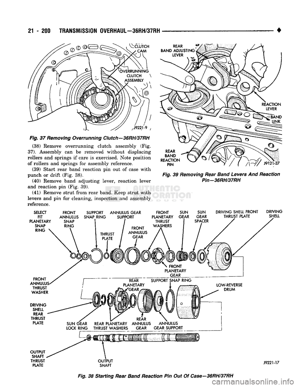
(38) Remove overrunning clutch assembly (Fig.
37).
Assembly can be removed without displacing
rollers and springs if care is exercised. Note position
of rollers and springs for assembly reference.
(39) Start rear band reaction pin out of case with
punch or drift (Fig. 38). (40) Remove band adjusting lever, reaction lever
and reaction pin (Fig. 39). (41) Remove strut from rear band. Keep strut with
levers and pin for cleaning, inspection and assembly
reference.
RtAR
BAND
REACTION PIN
Fig.
39
Removing
Rear
Band
Levers
And Reaction
Pin-36RH/37RH
SELECT
FIT
PLANETARY
SNAP
RING
FRONT
ANNULUS
SNAP
RING SUPPORT
SNAP
RING ANNULUS GEAR
SUPPORT
FRONT
ANNULUS
GEAR
FRONT
ANNULUS
THRUST
WASHER
DRIVING
SHELL
REAR
THRUST
PLATE
FRONT
PLANETARY
THRUST
WASHERS
SUN
GEAR
SUN
GEAR
SPACER
DRIVING SHELL
FRONT
DRIVING
THRUST
PLATE SHELL
SUN
GEAR
LOCK
RING
REAR
PLANETARY
THRUST
WASHERS
REAR
PLANETARY
GEAR
OUTPUT
SHAFT
THRUST
PLATE
OUTPUT
SHAFT
J9221-17
Fig.
38 Starting Rear
Band
Reaction Pin Out Of
Case—36RH/37RH
Page 1202 of 1502
•
TRANSMISSION
OVERHAUL—38RH/37RH
21 - 201
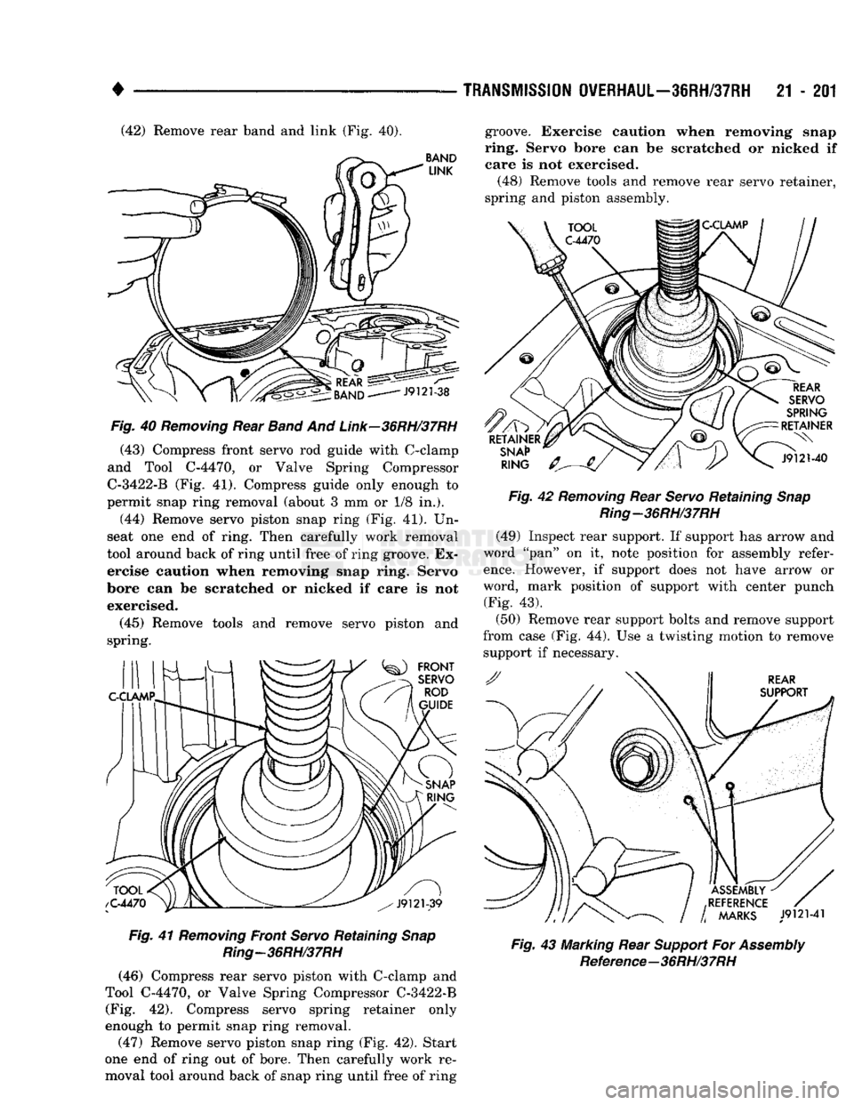
(42) Remove rear band and link (Fig. 40).
Fig.
40
Removing
Rear
Band
And
Link—36RH/37RH
(43) Compress front servo rod guide with C-clamp
and Tool C-4470, or Valve Spring Compressor
C-3422-B (Fig. 41). Compress guide only enough to
permit snap ring removal (about 3 mm or 1/8 in.).
(44) Remove servo piston snap ring (Fig. 41). Un
seat one end of ring. Then carefully work removal
tool around back of ring until free of ring groove. Ex ercise caution when removing snap ring. Servo
bore can be scratched or nicked if care is not exercised.
(45) Remove tools and remove servo piston and
spring.
Fig.
41
Removing
Front
Servo
Retaining
Snap
Ring—36RH/37RH (46) Compress rear servo piston with C-clamp and
Tool C-4470, or Valve Spring Compressor C-3422-B (Fig. 42). Compress servo spring retainer only
enough to permit snap ring removal.
(47) Remove servo piston snap ring (Fig. 42). Start
one end of ring out of bore. Then carefully work re
moval tool around back of snap ring until free of ring groove. Exercise caution when removing snap
ring. Servo bore can be scratched or nicked if
care is not exercised.
(48) Remove tools and remove rear servo retainer,
spring and piston assembly.
Fig.
42
Removing
Rear
Servo
Retaining
Snap
Ring—36RH/37RH
(49) Inspect rear support. If support has arrow and
word "pan" on it, note position for assembly refer
ence.
However, if support does not have arrow or
word, mark position of support with center punch
(Fig. 43).
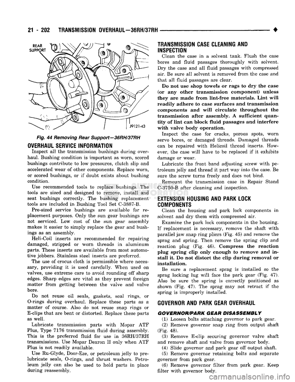
(50) Remove rear support bolts and remove support
from case (Fig. 44). Use a twisting motion to remove support if necessary.
Fig.
43 Marking Rear
Support
For
Assembly
Reference-36RH/37RH
Page 1203 of 1502
21
- 202
TRANSMISSION
OVERHAUL—36RH/37RH
•
Fig.
44
Removing
Rear Support—36RH/37RH
OVERHAUL
SERVICE
INFORMATION
Inspect
all the
transmission bushings during over
haul. Bushing condition
is
important
as
worn, scored
bushings contribute
to low
pressures, clutch slip
and
accelerated wear
of
other components. Replace worn,
or scored bushings,
or if
doubt exists about bushing
condition. Use recommended tools
to
replace bushings.
The
tools
are
sized
and
designed
to
remove, install
and
seat bushings correctly.
The
bushing replacement
tools
are
included
in
Bushing Tool
Set
C-3887-B. Pre-sized service bushings
are
available
for re
placement purposes. Only
the sun
gear bushings
are
not serviced.
Low
cost
of the sun
gear assembly
makes
it
easier
to
simply replace
the
gear
and
bush
ings
as an
assembly. Heli-Coil inserts
are
recommended
for
repairing
damaged, stripped
or
worn threads
in
aluminum
parts.
These inserts
are
available from most automo
tive jobbers. Stainless steel inserts
are
preferred. The
use of
crocus cloth
is
permissible where neces
sary, providing
it is
used carefully. When used
on
valves,
use
extreme care
to
avoid rounding
off
sharp
edges.
Sharp edges
are
vital
as
they prevent foreign
matter from getting between
the
valve
and
valve
bore.
Do
not
reuse
oil
seals, gaskets, seal rings,
or
O-rings during overhaul. Replace these parts
as a
matter
of
course. Also
do not
reuse snap rings
or
E-clips that
are
bent
or
distorted. Replace these parts as well.
Lubricate transmission parts with Mopar
ATF
Plus,
Type
7176
transmission fluid during assembly.
This
is the
preferred fluid
for use in
36RH/37RH transmissions.
Use
Mopar Dexron
II
only when
ATF
Plus
is not
readily available.
Use Ru-Glyde, Door-Eze,
or
petroleum jelly
to pre-
lubricate seals, O-rings,
and
thrust washers. Petro
leum jelly
can
also
be
used
to
hold parts
in
place during reassembly.
TRANSMISSION CASE
CLEAN1NI
AND
INSPECTION
Clean
the
case
in a
solvent tank. Flush
the
case
bores
and
fluid passages thoroughly with solvent.
Dry
the
case
and all
fluid passages with compressed air.
Be
sure
all
solvent
is
removed from
the
case
and
that
all
fluid passages
are
clear. Do
not use
shop towels
or
rags
to dry the
ease
(or
any
other transmission component) unless
they
are
made from lint-free materials. Lint will
readily adhere
to
case surfaces
and
transmission components
and
will circulate throughout
the
transmission after assembly.
A
sufficient quan
tity
of
lint
can
block fluid passages
and
interfere with valve body operation. Inspect
the
case
for
cracks, porous spots, worn
servo bores,
or
damaged threads. Damaged threads
can
be
repaired with Helicoil thread inserts. How
ever,
the
case will have
to be
replaced
if it
exhibits
damage
or
wear. Lubricate
the
front band adjusting screw with
pe
troleum jelly
and
thread
it
part
way
into
the
case.
Be
sure
the
screw turns freely
and
does
not
bind. Remount
the
transmission case
in
Repair Stand
C-3750-B after cleaning
and
inspection.
EXTENSION
HOUSING
AND PARK
LOCK
COMPONENTS
Clean
the
housing
and
park lock components
in
solvent
and dry
them with compressed
air.
Examine
the
park lock components
in the
housing.
If replacement
is
necessary, remove
the
shaft with
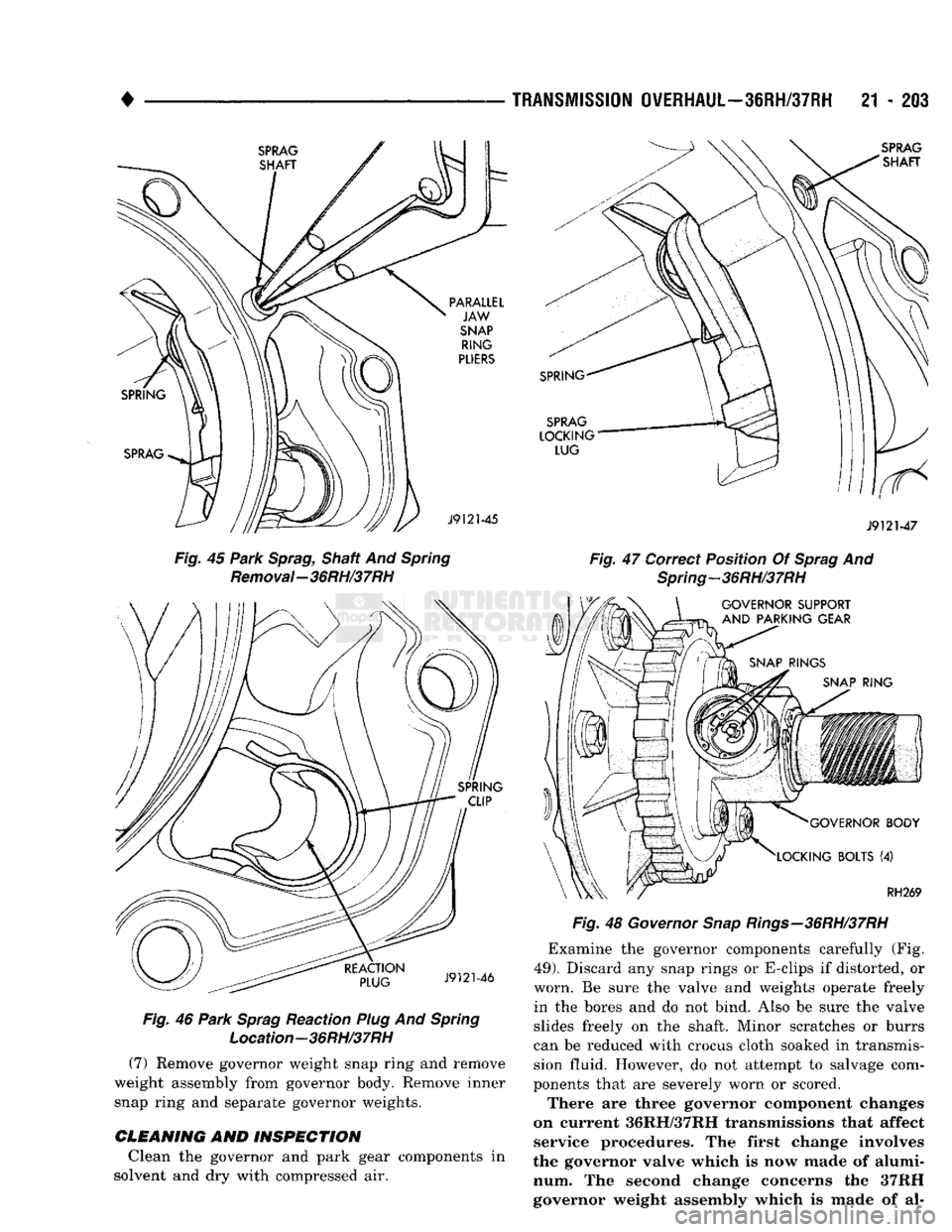
parallel
jaw
snap ring pliers
(Fig. 45) and
remove
the
sprag
and
spring. Then remove
the
spring clip
and
reaction plug
(Fig. 46).
Compress
the
reaction
plug spring clip only enough
to
remove
and in
stall
it. Do not
distort
the
clip during removal
or
installation. Be sure
a
replacement sprag
is
installed
so the
sprag locking
lug
will face
the
park gear
(Fig. 47).
Also
be
sure
the
spring
is
correctly positioned
as
shown
(Fig. 47). The
sprag
may not
retract
if the
spring
is
improperly installed.
GOVERNOR
AND PARK
GEAR OVERHAUL
GOWERNOR/PARK
GEAR DISASSEMBLY
(1) Loosen bolts attaching governor
to
park gear.
(2) Remove governor snap ring from output shaft
(Fig.
48).
(3) Remove E-clip securing governor valve shaft
and remove shaft
and
valve from governor body. (4) Slide governor
and
park gear
off
output shaft.
(5) Remove governor retaining bolts
and
separate
governor from park gear.
(6) Remove governor filter from park gear. Keep
filter with governor body.
Page 1204 of 1502
•
TRANSMISSION
OVERHAUL—36RH/37RH
21 - 203
Fig. 45 Park Sprag, Shaft And Spring Removal-36RH/37RH Fig. 46 Park Sprag Reaction Plug And Spring
Location-36RH/37RH
(7) Remove governor weight snap ring and remove
weight assembly from governor body. Remove inner
snap ring and separate governor weights. Fig. 48 Governor Snap Rings—36RH/37RH
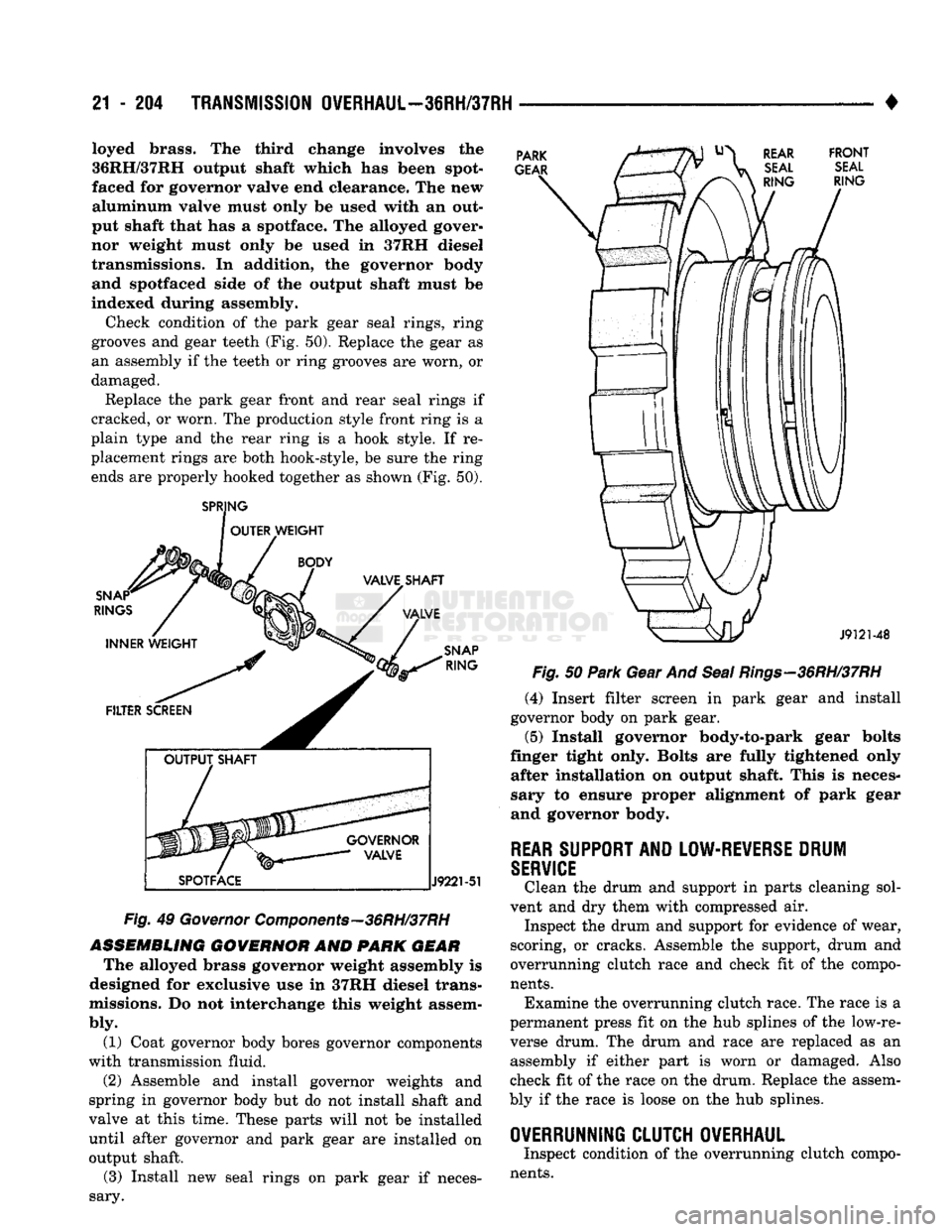
Examine the governor components carefully (Fig.
49).
Discard any snap rings or E-clips if distorted, or
worn. Be sure the valve and weights operate freely in the bores and do not bind. Also be sure the valve
slides freely on the shaft. Minor scratches or burrs
can be reduced with crocus cloth soaked in transmis
sion fluid. However, do not attempt to salvage com
ponents that are severely worn or scored.
There are three governor component changes
on current 36RH/37RH transmissions that affect service procedures. The first change involves
the governor valve which is now made of alumi num. The second change concerns the 37RH
governor weight assembly which is made of al-
CLEANING
AND
INSPECTION
Clean the governor and park gear components in
solvent and dry with compressed air.
Page 1205 of 1502
21 - 204
TRANSMISSION OVERHAUL—36RH/37RH
• loyed
brass.
The third change involves the
36RH/37RH
output
shaft
which
has been spot-
faced for governor valve end clearance. The new
aluminum
valve must only be used with an
out
put
shaft that
has a spotface. The alloyed gover
nor weight
must
only be
used
In 37RH diesel
transmissions. In addition, the governor body and spotfaced side of the output shaft must be
indexed during assembly.
Check condition of the park gear seal rings, ring
grooves and gear teeth (Fig. 50). Replace the gear as
an assembly if the teeth or ring grooves are worn, or damaged.
Replace the park gear front and rear seal rings if
cracked, or worn. The production style front ring is a
plain type and the rear ring is a hook style. If re
placement rings are both hook-style, be sure the ring ends are properly hooked together as shown (Fig. 50).
SPRJNG
OUTER WEIGHT PARK
GEAR REAR FRONT
SEAL SEAL
RING
RING SNAP*
RINGS
INNER WEIGHT VALVET SHAFT
VALVE
SNAP
RING
FILTER SCREEN
GOVERNOR VALVE
SPOTFACE
J9221-51
Fig.
49
Governor
Components—36RH/37RH
ASSEMBLING
GOVERNOR
AND PARK
GEAR
The alloyed brass governor weight assembly is
designed for exclusive use in 37RH diesel trans
missions. Do not interchange this weight assem
bly.
(1) Coat governor body bores governor components
with transmission fluid.
(2) Assemble and install governor weights and
spring in governor body but do not install shaft and
valve at this time. These parts will not be installed until after governor and park gear are installed on output shaft.
(3) Install new seal rings on park gear if neces
sary.
J9121-48
Fig.
50
Park
Gear And
Seal
Rings—36RH/37RH
(4) Insert filter screen in park gear and install
governor body on park gear.
(5)
Install governor body-to-park gear bolts
finger tight only. Bolts are fully tightened only after installation on output shaft. This is neces
sary to ensure proper alignment of park gear
and governor body.
REAR
SUPPORT
AND
LOW-REVERSE
DRUM
SERVICE
Clean the drum and support in parts cleaning sol
vent and dry them with compressed air. Inspect the drum and support for evidence of wear,
scoring, or cracks. Assemble the support, drum and
overrunning clutch race and check fit of the compo
nents.
Examine the overrunning clutch race. The race is a
permanent press fit on the hub splines of the low-re
verse drum. The drum and race are replaced as an assembly if either part is worn or damaged. Also
check fit of the race on the drum. Replace the assem
bly if the race is loose on the hub splines.
OVERRUNNING CLUTCH OVERHAUL
Inspect condition of the overrunning clutch compo
nents.
Page 1206 of 1502
•
TRANSMISSION
OVERHAUL—36RH/37RH
21 - 201 Replace the clutch cam if worn or damaged in any
way. Also check fit of the cam in the transmission
case.
If the cam is loose, the case may worn, or
cracked.
The clutch race is a permanent press fit on the low-
reverse drum hub splines. The drum and race are to
be replaced as an assembly if either part is worn or damaged. Replace the race and drum if the drum is
damaged or the race is spalled, scored, cracked, or
loose.
Examine the overrunning clutch rollers, springs
and retainer. Replace the assembly if the rollers are
worn, chipped, or cracked. Replace the assembly if
the springs are distorted, or damaged, or if the cage
type retainer is bent or broken.
If the clutch cam must be replaced, install the new
cam as follows:
REPLACING OVERRUNNING CLUTCH CAM
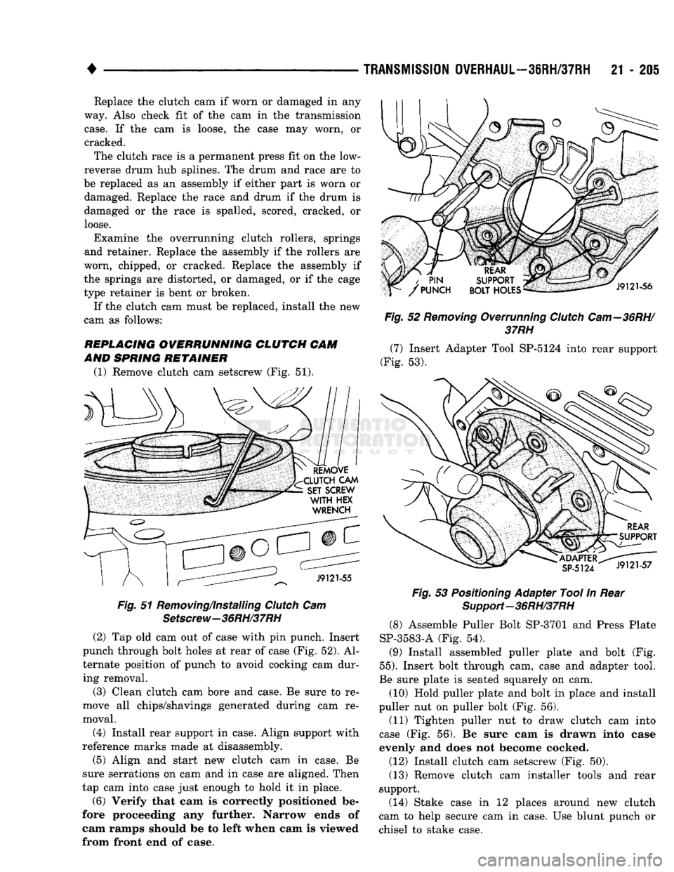
AND SPRING RETAINER (1) Remove clutch cam setscrew (Fig. 51). Fig. 51 Removing/installing Clutch Cam
Setscrew-36RH/37RH
(2) Tap old cam out of case with pin punch. Insert
punch through bolt holes at rear of case (Fig. 52). Al
ternate position of punch to avoid cocking cam dur ing removal.
(3) Clean clutch cam bore and case. Be sure to re
move all chips/shavings generated during cam re
moval.
(4) Install rear support in case. Align support with
reference marks made at disassembly. (5) Align and start new clutch cam in case. Be
sure serrations on cam and in case are aligned. Then
tap cam into case just enough to hold it in place.
(6)
Verify that cam is correctly positioned be
fore proceeding any further. Narrow ends of cam ramps should be to left when cam is viewed
from front end of case. Fig. 52 Removing Overrunning Clutch
Cam—36RH/
37RH (7) Insert Adapter Tool SP-5124 into rear support
(Fig. 53). Fig. 53 Positioning Adapter Tool In Rear
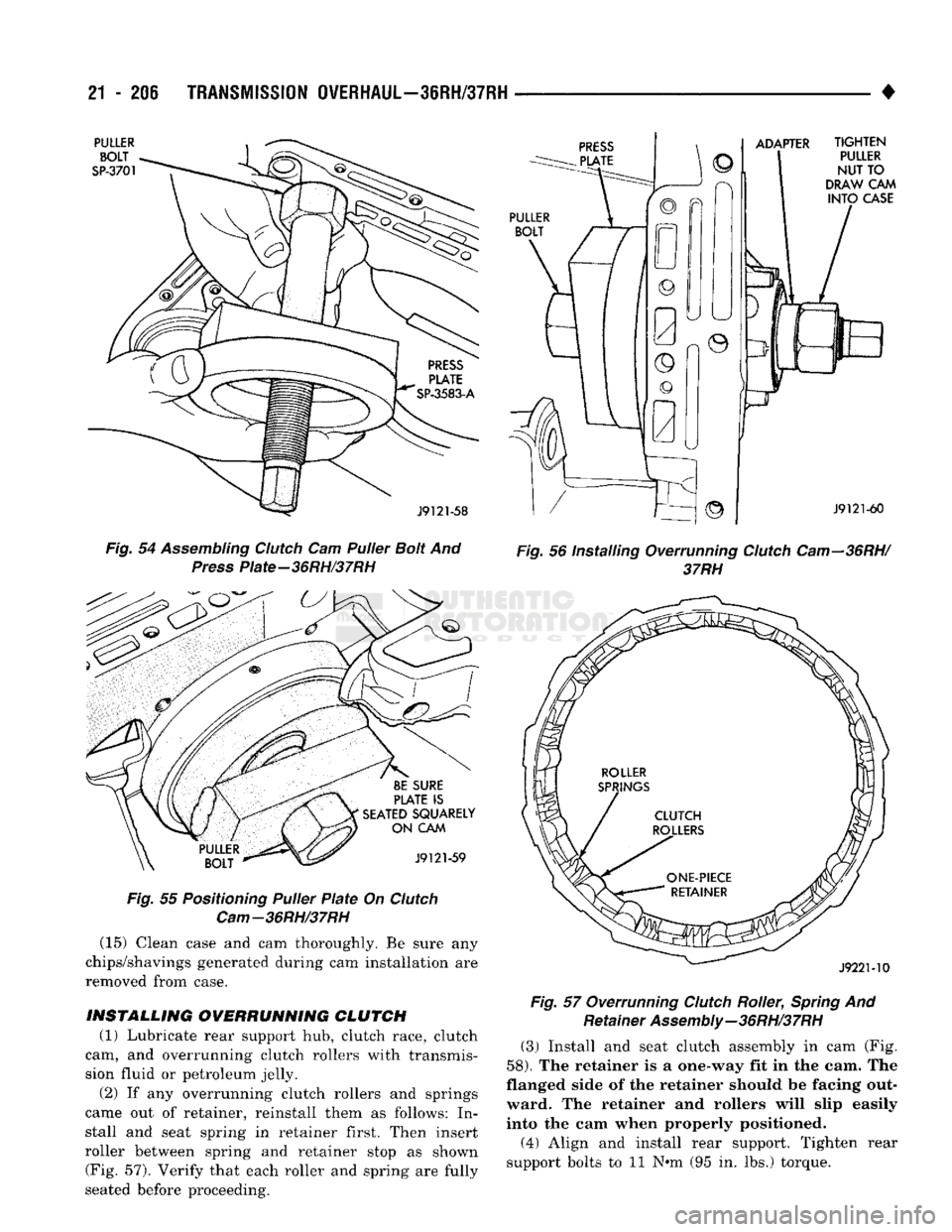
Support-36RH/37RH (8) Assemble Puller Bolt SP-3701 and Press Plate
SP-3583-A (Fig. 54).
(9) Install assembled puller plate and bolt (Fig.
55).
Insert bolt through cam, case and adapter tool.
Be sure plate is seated squarely on cam.
(10) Hold puller plate and bolt in place and install
puller nut on puller bolt (Fig. 56). (11) Tighten puller nut to draw clutch cam into
case (Fig. 56). Be sure cam Is
drawn Into
case
evenly and does not become cocked.
(12) Install clutch cam setscrew (Fig. 50).
(13) Remove clutch cam installer tools and rear
support.
(14) Stake case in 12 places around new clutch
cam to help secure cam in case. Use blunt punch or
chisel to stake case.
Page 1207 of 1502
21
- 206
TRANSMISSION
OVERHAUL—36RH/37RH
•
PULLER
BOLT
SP-3701
ADAPTER
J9121-58
Fig.
54
Assembling
Clutch
Cam Puller
Bolt
And
Press
Piate-36RH/37RH
BE
SURE
PLATE
IS
SEATED
SQUARELY
ON
CAM
J9121-59
Fig.
55
Positioning
Puller
Plate
On
Clutch
Cam-36RH/37RH (15) Clean case and cam thoroughly. Be sure any
chips/shavings generated during cam installation are
removed from case.
INSTALLING
OVERRUNNING
CLUTCH
(1) Lubricate rear support hub, clutch race, clutch
cam, and overrunning clutch rollers with transmis
sion fluid or petroleum jelly.
(2) If any overrunning clutch rollers and springs
came out of retainer, reinstall them as follows: In stall and seat spring in retainer first. Then insert
roller between spring and retainer stop as shown (Fig. 57). Verify that each roller and spring are fully
seated before proceeding.
TIGHTEN
PULLER
NUT TO
DRAW
CAM
INTO
CASE
J9121-60
Fig.
56 Installing Overrunning
Clutch
Cam—36RH/
37RH
J922M0
Fig.
57 Overrunning
Clutch
Roller,
Spring
And Retainer
Assembly—36RH/37RH
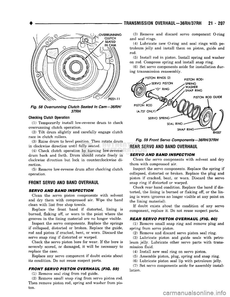
(3) Install and seat clutch assembly in cam (Fig.
58).
The retainer is a one-way fit in the cam. The
flanged side of the retainer should be facing out ward. The retainer and rollers will slip easily
into the cam when properly positioned.
(4) Align and install rear support. Tighten rear
support bolts to 11 N#m (95 in. lbs.) torque.
Page 1208 of 1502
TRANSMISSION
OVERHAUL—36RH/37RH
21 - 207
Fig.
58 Overrunning Clutch Seated in
Cam—36RH/
37RH
Checking
Clutch
Operation
(1) Temporarily install low-reverse drum to check
overrunning clutch operation.
(2) Tilt drum slightly and carefully engage clutch
race in clutch rollers.
(3) Raise drum to level position. Then rotate drum
in clockwise direction until fully seated.
(4) Check clutch operation by turning low-reverse
drum back and forth. Drum should rotate freely in
clockwise direction but lock in counterclockwise di
rection.
(5) Remove low-reverse drum after checking clutch
operation.
FRONT
SERVO
AND BAND OVERHAUL
SERVO
AND BAND INSPECTION Clean the servo piston components with solvent
and dry them with compressed air. Wipe the band
clean with lint free shop towels.
Replace the front band if distorted, lining is
burned, flaking off, or worn to the point where the grooves in the lining material are no longer visible.
Inspect the servo components. Replace the springs
if collapsed, distorted or broken. Replace the guide,
rod and piston if cracked, bent, or worn. Discard the servo snap ring if distorted or warped.
Check the servo piston bore for wear. If the bore is
severely scored, or damaged, it will be necessary to
replace the case.
Replace any servo component if doubt exists about
its condition. Do not reuse suspect parts.
FRONT SERVO PISTON OVERHAUL (FIG. 59) (1) Remove seal ring from rod guide.
(2) Remove small snap ring from servo piston rod.
Then remove piston rod, spring and washer from pis
ton. (3) Remove and discard servo component O-ring
and seal rings.
(4)
Lubricate new O-ring and seal rings with pe
troleum jelly and install them on piston, guide and rod.
(5) Install rod in piston. Install spring and washer
on rod. Compress spring and install snap ring.
(6) Set servo components aside for installation dur
ing transmission reassembly.
RH307
Fig.
59 Front
Servo
Components—36RH/37RH
REAR SERVO
AND BAND OVERHAUL
SERVO AND BAND INSPECTION Clean the servo components with solvent and dry
them with compressed air.
Inspect the servo components. Replace the spring if
collapsed, distorted or broken. Replace the plug and
piston if cracked, bent, or worn. Discard the servo snap ring if distorted or warped.
Check rear band condition. Replace the band if dis
torted, the lining is burned or flaking off, or the lin ing is worn (grooves no longer visible at any point on
the lining material).
If doubt exists about the condition of any servo
component, replace it. Do not reuse suspect parts.
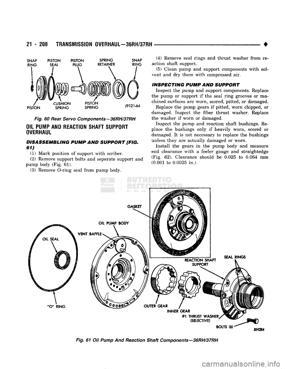
REAR SERVO PISTON OVERHAUL (FIG. 60) (1) Remove small snap ring and remove plug and
spring from servo piston.
(2) Remove and discard servo piston seal ring.
(3) Lubricate piston and guide seals with petro
leum jelly. Lubricate other servo parts with trans
mission fluid.
(4) Install new seal ring on servo piston.
(5) Assemble piston, plug, spring and snap ring. (6) Lubricate piston seal lip with petroleum jelly.
(7) Set servo components aside for assembly instal
lation.
Page 1209 of 1502
21
- 208
TRANSMISSION OVERHAUL—36RH/37RH
•
SNAP
RING
PISTON
SEAL
PISTON
PLUG
SPRING
RETAINER
SNAP
RING
PISTON
CUSHION
SPRING
PISTON
SPRING
J9121-64
Fig.
60 Rear
Servo
Components—36RH/37RH
OIL PUMP AND REACTION SHAFT SUPPORT
OVERHAUL
DISASSEMBLING PUMP AND SUPPORT (FIG.
61)
(1) Mark position of support with scriber.
(2) Remove support bolts and separate support and
pump body (Fig. 61). (3) Remove O-ring seal from pump body. (4) Remove seal rings and thrust washer from re
action shaft support. (5) Clean pump and support components with sol
vent and dry them with compressed air.
INSPECTING PUMP AND SUPPORT Inspect the pump and support components. Replace
the pump or support if the seal ring grooves or ma chined surfaces are worn, scored, pitted, or damaged. Replace the pump gears if pitted, worn chipped, or
damaged. Inspect the fiber thrust washer. Replace
the washer if worn or damaged.
Inspect the pump and reaction shaft bushings. Re
place the bushings only if heavily worn, scored or
damaged. It is not necessary to replace the bushings
unless they are actually damaged or worn.
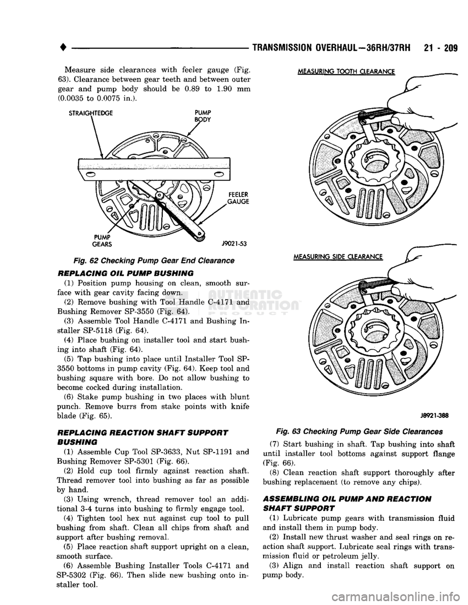
Install the gears in the pump body and measure
end clearance with a feeler gauge and straightedge (Fig. 62). Clearance should be 0.025 to 0.064 mm
(0.001 to 0.0025 in.).
Fig.
61 Oil
Pump
And Reaction Shaft
Components—36RH/37RH
Page 1210 of 1502
•
TRANSMISSION
OVERHAUL—36RH/37RH
21 - 209 Measure side clearances with feeler gauge (Fig.
63).
Clearance between gear teeth and between outer
gear and pump body should be 0.89 to 1.90 mm (0.0035 to 0.0075 in.).
STRAIGHTEDGE
PUMP
Fig.
62
Checking Pump
Gear End Clearance
REPLACING
OIL
PUMP BUSHING
(1) Position pump housing on clean, smooth sur
face with gear cavity facing down.
(2) Remove bushing with Tool Handle C-4171 and
Bushing Remover SP-3550 (Fig. 64).
(3) Assemble Tool Handle C-4171 and Bushing In
staller SP-5118 (Fig. 64). (4) Place bushing on installer tool and start bush
ing into shaft (Fig. 64).
(5) Tap bushing into place until Installer Tool SP-
3550 bottoms in pump cavity (Fig. 64). Keep tool and
bushing square with bore. Do not allow bushing to
become cocked during installation.
(6) Stake pump bushing in two places with blunt
punch. Remove burrs from stake points with knife
blade (Fig. 65).
REPLACING
REACTION SHAFT SUPPORT
BUSHING
(1) Assemble Cup Tool SP-3633, Nut SP-1191 and
Bushing Remover SP-5301 (Fig. 66). (2) Hold cup tool firmly against reaction shaft.
Thread remover tool into bushing as far as possible
by hand.
(3) Using wrench, thread remover tool an addi
tional 3-4 turns into bushing to firmly engage tool.
(4) Tighten tool hex nut against cup tool to pull
bushing from shaft. Clean all chips from shaft and support after bushing removal.
(5) Place reaction shaft support upright on a clean,
smooth surface.
(6) Assemble Bushing Installer Tools C-4171 and
SP-5302 (Fig. 66). Then slide new bushing onto in
staller tool.
J8921-388
Fig.
63
Checking Pump
Gear
Side
Clearances
(7) Start bushing in shaft. Tap bushing into shaft
until installer tool bottoms against support flange
(Fig. 66).
(8) Clean reaction shaft support thoroughly after
bushing replacement (to remove any chips).
ASSEMBLING
OIL
PUMP
AND
REACTION SHAFT SUPPORT
(1) Lubricate pump gears with transmission fluid
and install them in pump body.
(2) Install new thrust washer and seal rings on re
action shaft support. Lubricate seal rings with trans
mission fluid or petroleum jelly.
(3) Align and install reaction shaft support on
pump body.