DODGE TRUCK 1993 Service Repair Manual
Manufacturer: DODGE, Model Year: 1993, Model line: TRUCK, Model: DODGE TRUCK 1993Pages: 1502, PDF Size: 80.97 MB
Page 891 of 1502
14
- 72
FUEL
SYSTEM
•
MANIFOLD ABSOLUTE
Fig.
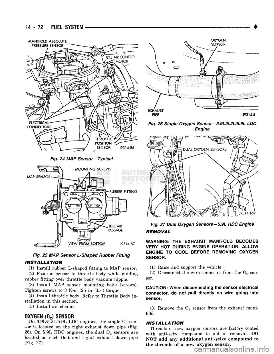
24 MAP
Sensor—
Typical
Fig.
25 MAP
Sensor L-Shaped Rubber
Fitting
INSTALLATION
(1) Install rubber L-shaped fitting to MAP sensor.
(2) Position sensor to throttle body while guiding
rubber fitting over throttle body vacuum nipple.
(3) Install MAP sensor mounting bolts (screws).
Tighten screws to 3 N»m (25 in. lbs.) torque.
(4) Install throttle body. Refer to Throttle Body in
stallation in this section. (5) Install air cleaner.
OXYGEN
(02)
SENSOR
On 3.9L/5.2L/5.9L LDC engines, the single 02 sen
sor is located on the right exhaust down pipe (Fig.
26).
On 5.9L HDC engines, the dual 02 sensors are
located on each (left and right) exhaust down pipe (Fig. 27).
Fig.
27
Dual Oxygen Sensors—5.9L
HDC
Engine
REMOVAL
WARNING:
THE
EXHAUST MANIFOLD BECOMES
VERY
HOT
DURING ENGINE OPERATION. ALLOW ENGINE
TO
COOL BEFORE REMOVING OXYGEN
SENSOR.
(1) Raise and support the vehicle.
(2) Disconnect the wire connector from the 02 sen
sor.
CAUTION:
When
disconnecting
the
sensor
electrical
connector,
do not
pull directly
on
wire
going
into
sensor.
(3) Remove the 02 sensor from the exhaust mani
fold.
INSTALLATION
Threads of new oxygen sensors are factory coated
with anti-seize compound to aid in removal. DO NOT add any additional anti-seize compound to
the threads of a new oxygen sensor.
Page 892 of 1502
•
FUEL SYSTEM
14-73 (1) Install the 02 sensor into the exhaust manifold.
Tighten to 30 N*m (22 ft. lbs.) torque.
(2) Connect the 02 sensor wire connector.
(3) Lower the vehicle.
PARK/NEUTRAL
SWITCH
Refer to Group 21, Transmission and Transfer Case
for removal/installation procedures.
POWERTRAIN CONTROL MODULE
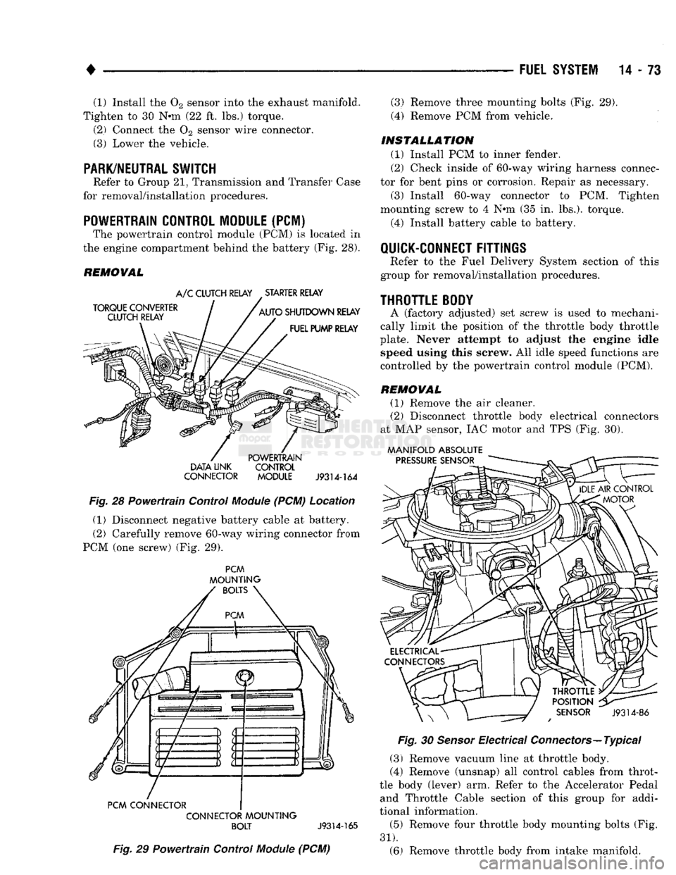
(PCM) The powertrain control module (PCM) is located in
the engine compartment behind the battery (Fig. 28).
REMOVAL
DATA LINK CONTROL
CONNECTOR MODULE
J9314-164
Fig.
28 Powertrain Control
Module
(PCM) Location (1) Disconnect negative battery cable at battery.
(2) Carefully remove 60-way wiring connector from
PCM (one screw) (Fig. 29).
PCM
MOUNTING
PCM CONNECTOR CONNECTOR
MOUNTING
BOLT
J9314-165
Fig.
29 Powertrain Control
Module
(PCM) (3) Remove three mounting bolts (Fig. 29).
(4) Remove PCM from vehicle.
INSTALLATION
(1) Install PCM to inner fender.
(2) Check inside of 60-way wiring harness connec
tor for bent pins or corrosion. Repair as necessary.
(3) Install 60-way connector to PCM. Tighten
mounting screw to 4 Nem (35 in. lbs.), torque.
(4) Install battery cable to battery.
QUICK-CONNECT
FITTINGS
Refer to the Fuel Delivery System section of this
group for removal/installation procedures.
THROTTLE
BODY
A (factory adjusted) set screw is used to mechani
cally limit the position of the throttle body throttle
plate. Never attempt to adjust the engine idle speed using this screw. All idle speed functions are
controlled by the powertrain control module (PCM).
REMOVAL
(1) Remove the air cleaner.
(2) Disconnect throttle body electrical connectors
at MAP sensor, IAC motor and TPS (Fig. 30).
MANIFOLD ABSOLUTE
Fig.
30
Sensor
Electrical Connectors—Typical
(3) Remove vacuum line at throttle body.
(4) Remove (unsnap) all control cables from throt
tle body (lever) arm. Refer to the Accelerator Pedal and Throttle Cable section of this group for addi
tional information.
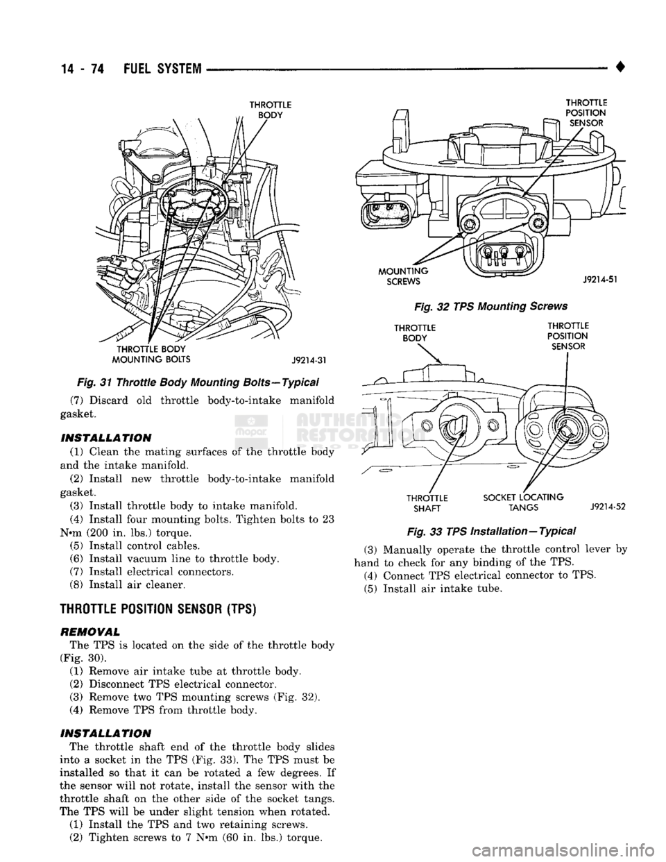
(5) Remove four throttle body mounting bolts (Fig.
31).
(6) Remove throttle body from intake manifold.
Page 893 of 1502
14
- 74
FUEL
SYSTEM
•
THROTTLE
THROTTLE BODY
MOUNTING BOLTS J9214-31
Fig.
31
Throttle
Body
Mounting
Bolts—Typical (7) Discard old throttle body-to-intake manifold
gasket.
INSTALLATION (1) Clean the mating surfaces of the throttle body
and the intake manifold.
(2) Install new throttle body-to-intake manifold
gasket.
(3) Install throttle body to intake manifold.
(4) Install four mounting bolts. Tighten bolts to 23
N»m (200 in. lbs.) torque. (5) Install control cables.
(6) Install vacuum line to throttle body.
(7) Install electrical connectors.
(8) Install air cleaner.
THROTTLE
POSITION
SENSOR
(TPS)
REMOVAL
The TPS is located on the side of the throttle body
(Fig. 30).
(1) Remove air intake tube at throttle body. (2) Disconnect TPS electrical connector.
(3) Remove two TPS mounting screws (Fig. 32).
(4) Remove TPS from throttle body.
INSTALLATION The throttle shaft end of the throttle body slides
into a socket in the TPS (Fig. 33). The TPS must be
installed so that it can be rotated a few degrees. If
the sensor will not rotate, install the sensor with the
throttle shaft on the other side of the socket tangs.
The TPS will be under slight tension when rotated.
(1) Install the TPS and two retaining screws. (2) Tighten screws to 7 N»m (60 in. lbs.) torque.
THROTTLE
Fig.
32 TPS
Mounting
Screws THROTTLE THROTTLE
BODY
POSITION
THROTTLE SOCKET LOCATING
SHAFT
TANGS
J9214-52
Fig.
33 TPS
Installation—Typical
(3) Manually operate the throttle control lever by
hand to check for any binding of the TPS. (4) Connect TPS electrical connector to TPS.
(5) Install air intake tube.
Page 894 of 1502
•
FUEL
SYSTEM
14-75
VEHICLE SPEED SENSOR
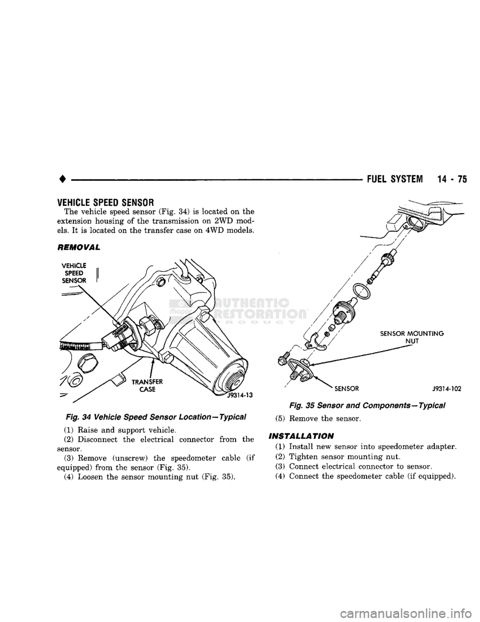
The vehicle speed sensor (Fig. 34) is located on the
extension housing of the transmission on 2WD mod
els.
It is located on the transfer case on 4WD models.
REMOVAL Fig. 34 Vehicle Speed Sensor Location—Typical
(1) Raise and support vehicle.
(2) Disconnect the electrical connector from the
sensor. (3) Remove (unscrew) the speedometer cable (if
equipped) from the sensor (Fig. 35). (4) Loosen the sensor mounting nut (Fig. 35). Fig. 35 Sensor and Components—Typical
(5) Remove the sensor.
INSTALLATION
(1) Install new sensor into speedometer adapter.
(2) Tighten sensor mounting nut.
(3) Connect electrical connector to sensor.
(4) Connect the speedometer cable (if equipped).
Page 895 of 1502
DIESEL
FUEL
INJECTION—COMPONENT
DESCRIPTION/SYSTEM
OPERATION
NDEX
page
Air
Conditioning (A/C) Clutch
Relay-PCM
Output
. 81
Air
Conditioning (A/C)
Controls-PCM
Input
.... 77
Air
Intake Heater
Relays—PCM
Output
........ 81
Auto
Shut
Down
(ASD)
Relay-PCM
Output
.... 82
Automatic
Shut
Down
(ASD)
Sense-PCM
input
. 78
Battery
Voltage-PCM
Input
78
Brake
Switch—PCM
Input
....... 78
Charge
Air
Temperature
Sensor—PCM
Input
... 78
Engine
Speed
Sensor—PCM
Input
........... 78
Fuel
Drain Manifold
83
Fuel
Heater
83
Fuel
Injection
Pump
83
Fuel
Injectors
84
Fuel
Solenoid
84
Fuel/Water
Separator
Filter ................. 84
General
Information
76
Generator
Field-PCM
Output
. 81
High
Pressure
Fuel
Lines
85
Ignition
Sense—PCM
Input
78
KSB
Solenoid
....... 85
Malfunction Indicator
Lamp—PCM
Output
...... 82
Manual
Shut
Down
Lever
.................. 85
GENERAL
INFORMATION
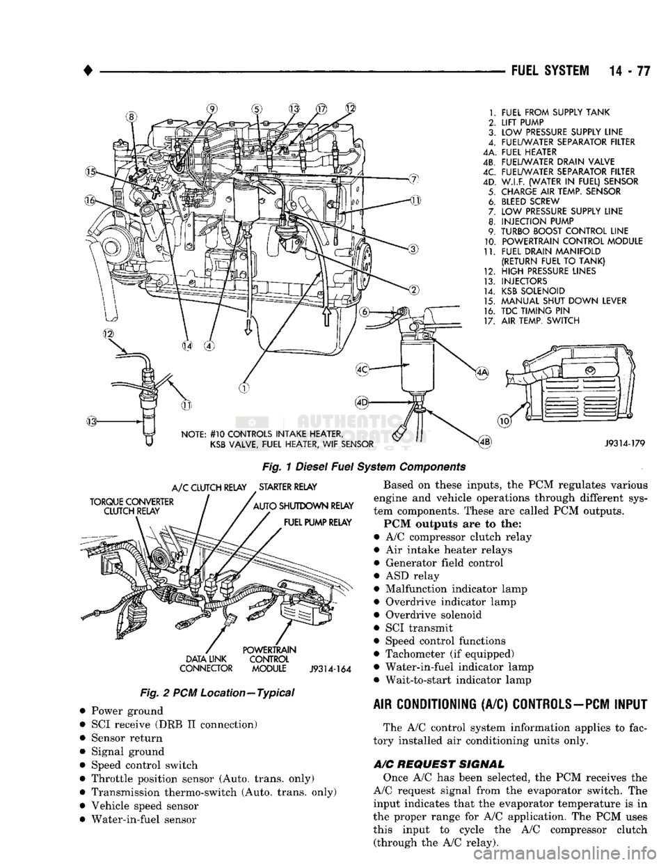
The fuel system of the 5.9L (in-line six-cylinder)
turbo-diesel engine (Fig. 1) consists of the following components:
• Fuel tank
• Low and high pressure fuel supply lines
• Mechanical lift pump
• Fuel/water separator filter
• Fuel heater
• Fuel injection pump
• Fuel injectors • Fuel return lines For information regarding fuel requirements of the
5.9L turbo-diesel engine, refer to the Fuel Require
ments—Diesel Engines paragraph at the front of this group. Although various components, relays and switches
are operated by the powertrain control module (PCM), the diesel fuel injection system (Fig. 1) is not
directly regulated by the PCM. Refer to the proceed
ing Powertrain Control Module section for additional
information.
SYSTEM
DIAGNOSIS
The PCM tests many of its own input and output
circuits. If a diagnostic trouble code (DTC) is found in a major system, this information is stored in the
PCM memory. Refer to On-Board Diagnostics in the Diesel Fuel Injection—General Diagnosis section of
page
Mechanical
Lift
Pump
86
Overdrive
Indicator
Lamp—PCM
Output
....... 82
Overdrive
Solenoid-PCM
Output
............ 82
Overdrive/Override
Switch—PCM
Input
........ 79
Park/Neutral
Switch-PCM
Input
79
Power
Ground-PCM
Input
. 79
Powertrain Control Module
(PCM)
76
SCI
Receive-PCM
Input
. . 80
SCI
Transmit-PCM
Output
. . . 82
Sensor
Return-PCM
Input
................. 80
Signal
Ground-PCM
Input
. 80
Speed
Control-PCM
Input
80
Speed
Control-PCM
Output
82
System
Diagnosis
76
System
Operation
86
Tachometer-PCM
Output
82
Throttle
Position
Sensor
(TPS)-PCM
Input
80
Vehicle
Speed
Sensor-PCM
Input
80
Wait-To-Start
Lamp-PCM
Output
82
Water-ln-Fuel
Lamp-PCM
Output
83
Water-ln-Fuel
Sensor-PCM
input
80
this group for DTC information. The DRB II scan tool can be used to access the DTC messages stored in the PCM memory.
POWERTRAIN
CONTROL
MODULE
(PCM)
The powertrain control module (PCM) (Fig. 2) was
formerly referred to as the SBEC or engine control ler. The PCM is a pre-programmed, dual micropro
cessor digital computer. The PCM is located in the engine compartment be
hind the battery and under the left front fender (Fig.
2).
The PCM contains a voltage convertor, which con
verts battery voltage to a regulated 8.0 volts. This is used to power the engine speed sensor. The PCM also
provides a 5 volt supply for the throttle position sensor (TPS). The TPS is not used if equipped with a
manual transmission.
Various sensors, switches and relays provide the
inputs necessary for operation of the PCM.
The PCM Inputs are from:
9
Air conditioning control switch
• Automatic shut down (ASD) sense circuit
• Battery voltage
• Brake light switch • Charge air temperature sensor ® Coolant temperature sensor (Auto, trans, only)
• Engine speed sensor
• Ignition
• Overdrive/override switch
• Park/neutral switch (Auto, trans, only)
Page 896 of 1502
•
FUEL
SYSTEM
14-77
FUEL FROM SUPPLY TANK
LIFT
PUMP
LOW
PRESSURE
SUPPLY LINE
FUEL/WATER SEPARATOR FILTER
4A. FUEL HEATER
4B. FUEL/WATER DRAIN VALVE
FUEL/WATER SEPARATOR FILTER
W.I.F. (WATER
IN
FUEL) SENSOR
CHARGE
AIR
TEMP. SENSOR
BLEED
SCREW
LOW
PRESSURE
SUPPLY LINE
INJECTION PUMP
TURBO BOOST CONTROL LINE POWERTRAIN CONTROL MODULE
FUEL DRAIN MANIFOLD
(RETURN FUEL
TO
TANK)
HIGH
PRESSURE
LINES
INJECTORS
KSB
SOLENOID
MANUAL SHUT DOWN LEVER
TDC TIMING
PIN
AIR TEMP. SWITCH
NOTE: #10 CONTROLS INTAKE HEATER,
KSB
VALVE, FUEL HEATER,
WIF
SENSOR
J9314-179
Fig.
1
Diesel
Fuel
System
Components
TORQUE CONVERTER CLUTCH RELAY
A/C
CLUTCH RELAY STARTER RELAY
AUTO SHUTDOWN RELAY FUEL PUMP RELAY DATA UNK
CONNECTOR POWERTRAIN
CONTROL
MODULE
J9314-164
Fig.
2 PCM Location—Typical Power ground
SCI receive (DRB II connection)
Sensor return
Signal ground
Speed control switch
Throttle position sensor (Auto, trans, only)
Transmission thermo-switch (Auto, trans, only)
Vehicle speed sensor
Water-in-fuel sensor Based on these inputs, the PCM regulates various
engine and vehicle operations through different sys
tem components. These are called PCM outputs.
PCM outputs are to the:
• A/C compressor clutch relay
• Air intake heater relays
• Generator field control
• ASD relay
• Malfunction indicator lamp
• Overdrive indicator lamp
• Overdrive solenoid
• SCI transmit
• Speed control functions
• Tachometer (if equipped)
• Water-in-fuel indicator lamp • Wait-to-start indicator lamp
AIR CONDITIONING
(A/C)
CONTROLS-PCM
INPUT
The A/C control system information applies to fac
tory installed air conditioning units only.
A/C
REQUEST SIGNAL
Once A/C has been selected, the PCM receives the
A/C request signal from the evaporator switch. The input indicates that the evaporator temperature is in
the proper range for A/C application. The PCM uses this input to cycle the A/C compressor clutch (through the A/C relay).
Page 897 of 1502
14-78
FUEL SYSTEM
• If
the A/C low
pressure switch opens (indicating
a
low refrigerant level),
the PCM
will
not
receive
an
A/C select signal.
The PCM
will then remove
the
ground from
the A/C
relay. This will deactivate
the
A/C compressor clutch.
If evaporator switch opens, (indicating that evapo
rator
is not in
proper temperature range),
PCM
will
not receive
the A/C
request signal.
The PCM
will
then remove
the
ground from
the A/C
relay, deacti
vating
the A/C
compressor clutch.
AUTOMATIC SHUT DOWN
(ASD)
SENSE-PCM
INPUT
A
12
volt signal
at
this input indicates
to the PCM
that
the ASD has
been activated.
The ASD
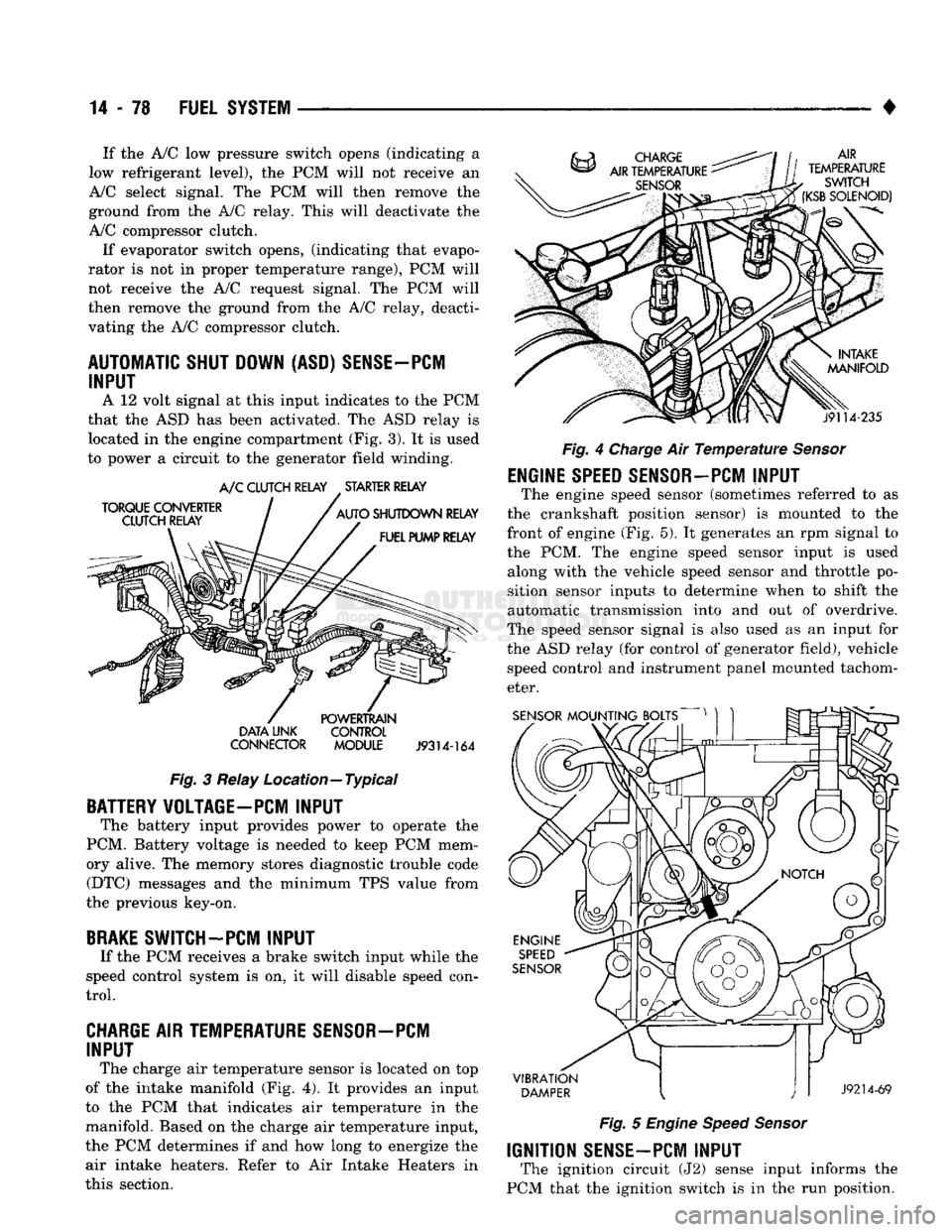
relay
is
located
in the
engine compartment
(Fig.
3).
It is
used
to power
a
circuit
to the
generator field winding.
TORQUE
CONVERTER
CLUTCH RELAY A/C
CLUTCH RELAY
.
STARTER RELAY
AUTO
SHUTDOWN
RELAY
FUEL PUMP RELAY
DATA
LINK
CONNECTOR
POWERTRAIN
CONTROL
MODULE
J9314-164
Fig.
3
Relay Location—Typical
BATTERY VOLTAGE-PC! INPUT
The battery input provides power
to
operate
the
PCM. Battery voltage
is
needed
to
keep
PCM
mem
ory alive.
The
memory stores diagnostic trouble code (DTC) messages
and the
minimum
TPS
value from
the previous key-on,
BRAKE
SWITCH-PCM INPUT
If
the PCM
receives
a
brake switch input while
the
speed control system
is on, it
will disable speed con
trol.
CHARGE AIR TEMPERATURE SENSOR—PCM INPUT
The charge
air
temperature sensor
is
located
on top
of
the
intake manifold
(Fig. 4). It
provides
an
input
to
the PCM
that indicates
air
temperature
in the
manifold. Based
on the
charge
air
temperature input,
the
PCM
determines
if and how
long
to
energize
the
air intake heaters. Refer
to Air
Intake Heaters
in
this section. AIR
TEMPERATURE
SWITCH
(KSB
SOLENOID)
j9114-235
Fig.
4
Charge
Air
Temperature Sensor
ENGINE
SPEED
SENSOR-PCM
INPUT
The engine speed sensor (sometimes referred
to as
the crankshaft position sensor)
is
mounted
to the
front
of
engine
(Fig. 5). It
generates
an rpm
signal
to
the
PCM. The
engine speed sensor input
is
used along with
the
vehicle speed sensor
and
throttle
po
sition sensor inputs
to
determine when
to
shift
the
automatic transmission into
and out of
overdrive.
The speed sensor signal
is
also used
as an
input
for
the
ASD
relay
(for
control
of
generator field), vehicle speed control
and
instrument panel mounted tachom
eter.
SENSOR
MOUNTING BOLTS
VIBRATION
DAMPER
J9214-69
Fig.
5
Engine Speed Sensor
IGNITION
SENSE-PCM
INPUT
The ignition circuit
(J2)
sense input informs
the
PCM that
the
ignition switch
is in the run
position.
Page 898 of 1502
•
FUEL SYSTEM
14-79
OVERDRIVE/OVERRIDE SWITCH-PCM
INPUT
The overdrive/override switch is not used with
manual transmissions. On vehicles equipped with overdrive, the PCM reg
ulates the 3-4 overdrive upshift and downshift
through the overdrive solenoid. An override switch is located on the instrument panel. The overdrive/override switch is a momentary con
tact switch. The switch contacts are normally open. When the switch is activated, the PCM will receive a ground signal. The transmission will not enter over
drive when the operator presses the override switch.
The transmission downshifts if the operator presses
the override switch while in overdrive.
COOLANT TEMPERATURE SENSOR The coolant temperature sensor is not used with
manual transmissions.
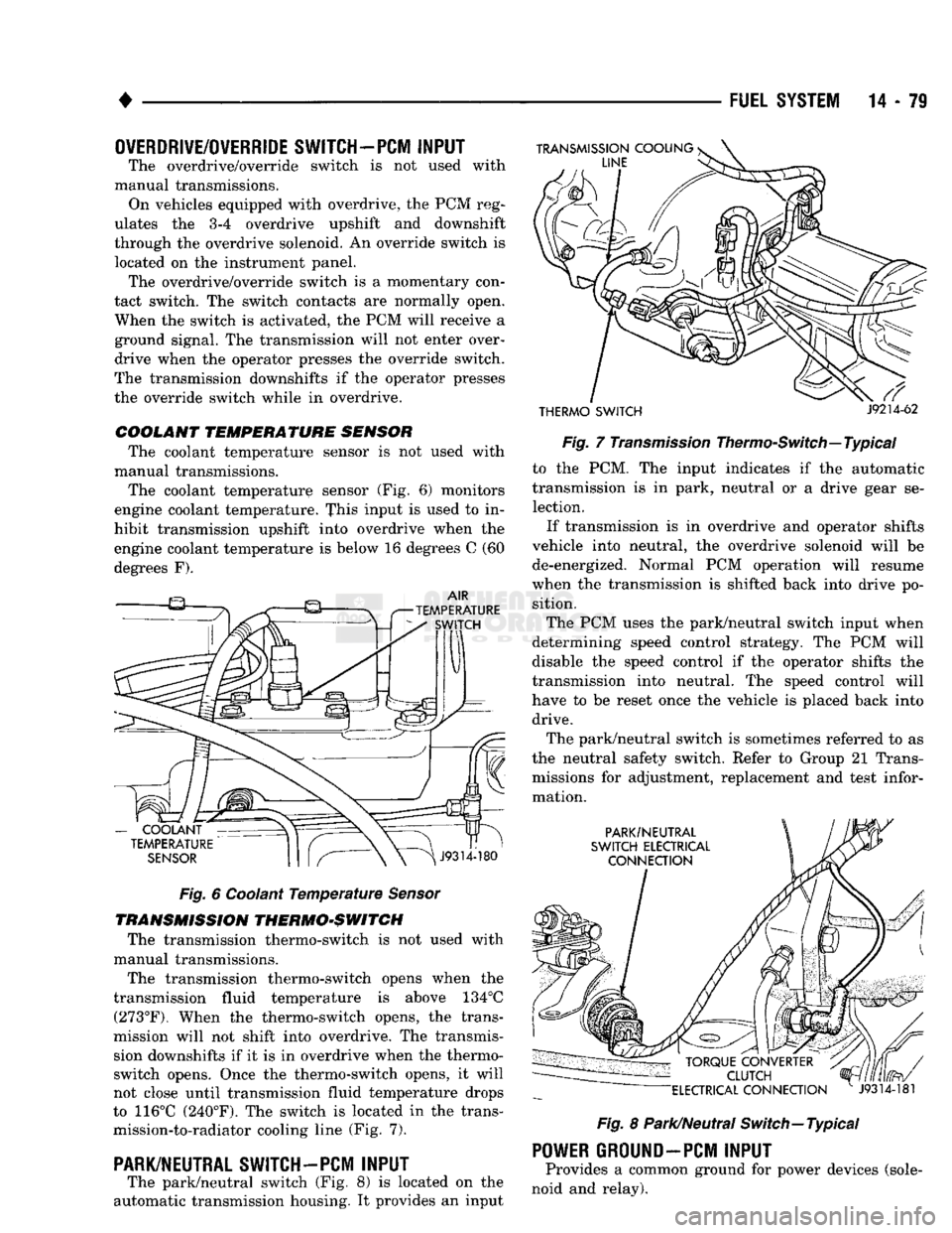
The coolant temperature sensor (Fig. 6) monitors
engine coolant temperature. This input is used to in
hibit transmission upshift into overdrive when the
engine coolant temperature is below 16 degrees C (60
degrees F).
Fig.
6 Coolant
Temperature
Sensor
TRANSMISSION THERMO-SWITCH The transmission thermo-switch is not used with
manual transmissions.
The transmission thermo-switch opens when the
transmission fluid temperature is above 134°C (273°F). When the thermo-switch opens, the trans
mission will not shift into overdrive. The transmis sion downshifts if it is in overdrive when the thermo-
switch opens. Once the thermo-switch opens, it will
not close until transmission fluid temperature drops
to 116°C (240°F). The switch is located in the trans mission-to-radiator cooling line (Fig. 7).
PARK/NEUTRAL SWITCH-PCM
INPUT
The park/neutral switch (Fig. 8) is located on the
automatic transmission housing. It provides an input
THERMO SWITCH
J9214-62
Fig.
7
Transmission
Thermo-Switch—Typical to the PCM. The input indicates if the automatic
transmission is in park, neutral or a drive gear se lection.
If transmission is in overdrive and operator shifts
vehicle into neutral, the overdrive solenoid will be de-energized. Normal PCM operation will resume
when the transmission is shifted back into drive po sition.
The PCM uses the park/neutral switch input when
determining speed control strategy. The PCM will
disable the speed control if the operator shifts the
transmission into neutral. The speed control will
have to be reset once the vehicle is placed back into drive.
The park/neutral switch is sometimes referred to as
the neutral safety switch. Refer to Group 21 Trans missions for adjustment, replacement and test infor
mation.
Fig.
8 Park/Neutral Switch—Typical
POWER
GROUND-PCM
INPUT
Provides a common ground for power devices (sole
noid and relay).
Page 899 of 1502
14 - 80
FUEL SYSTEM
•
SCI
RECEIVE-PCM
INPUT
The serial communication interface (SCI) receive
and transmit outputs allow the PCM to communicate
with the DRB II scan tool.
SENSOR
RETURN-PCM
INPUT
Sensor return provides a low noise ground refer
ence for all system sensors.
SIGNAL
GROUND-PCM
INPUT
Provides a common ground for the input signals.
SPEED
CONTROL-PCM
INPUT
The PCM regulates the speed control system based
on inputs it receives. The speed control operating
range is from 35 to 85 mph. Inputs that effect speed control operation are:
• Park/neutral switch
• Vehicle speed sensor
• Throttle position sensor
• Engine speed sensor
• Brake switch
THROTTLE
POSITION SENSOR (TPS) —PCM
INPUT
The throttle position sensor is not used with man
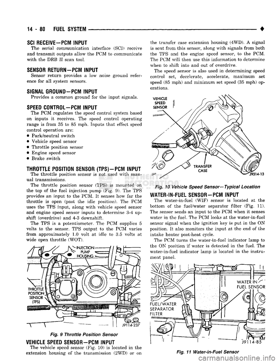
ual transmissions. The throttle position sensor (TPS) is mounted on
the top of the fuel injection pump (Fig. 9). The TPS
provides an input to the PCM. It senses how far the
throttle is open (past the idle position). The PCM uses the TPS input, along with vehicle speed sensor and engine speed sensor inputs to determine 3-4 up
shift (overdrive) and 4-3 downshift. The TPS is a potentiometer. The PCM supplies 5
volts to the sensor. TPS output to the PCM varies
from approximately 1.0 volt at idle to 3.5 volts at
wide open throttle (WOT). T
J9114-237
Fig.
9
Throttle
Position
Sensor
VEHICLE SPEED SENSOR-PCM
INPUT
The vehicle speed sensor (Fig. 10) is located in the
extension housing of the transmission (2WD) or on the transfer case extension housing (4WD). A signal
is sent from this sensor, along with signals from both
the TPS and the engine speed sensor, to the PCM.
The PCM will then use this information to determine
when to shift into and out of overdrive.
The speed sensor is also used in determining speed
control set, decelerate, accelerate, maximum set
speed (85 mph) and minimum set speed (35 mph) op
erations.
VEHICLE
SPEED
SENSOR
Fig.
10 Vehicle
Speed
Sensor—Typical Location
WATER-IN-FUEL SENSOR-PCM
INPUT
The water-in-fuel (WIF) sensor is located at the
bottom of the fuel/water separator filter (Fig. 11). The sensor sends an input to the PCM when it senses
water in the fuel. The PCM looks at the water-in-fuel sensor signal when the ignition key is put in the ON
position. It also monitors the input at the end of the intake heater post-heat cycle. The PCM turns the water-in-fuel indicator lamp to
the ON position if water is detected in the fuel. The
water-in-fuel indicator lamp is located in the instru ment panel.
J91 14-85
Fig.
11 Water-in-Fuel
Sensor
Page 900 of 1502
•
FUEL
SYSTEM
14-81
AIR
CONDITIONING
(A/C)
CLUTCH RELAY—PCM
OUTPUT
The PCM activates the A/C compressor through the
A/C clutch relay. The PCM regulates A/C compressor
operation by switching the ground circuit for the A/C
clutch relay on and off. The relay is located in the engine compartment (Fig. 3). By switching the ground path for the relay on and
off, the PCM is able to cycle the A/C compressor
clutch. This is based on changes in engine operating
conditions. If, during A/C operation, the PCM senses
a low idle speed, it will de-energize the relay. This
prevents A/C clutch engagement. The relay will re main de-energized until the idle speed increases.
GENERATOR
FIELD-PCM
OUTPUT
The PCM regulates the charging system voltage
within a range of 12.9 to 15.0 volts. It will control
ASD relay operation. The input (through the PCM)
for the ASD relay comes from the engine speed sen sor. When engine running speed is above 384 rpm, a
signal is sent from the PCM to engage the ASD re
lay. This supplies the necessary generator field wind
ing control. When rpm drops below 320, the signal to
the ASD relay is stopped. Refer to Group 8A, for charging system information.
AIR INTAKE HEATER RELAYS-PCM
OUTPUT
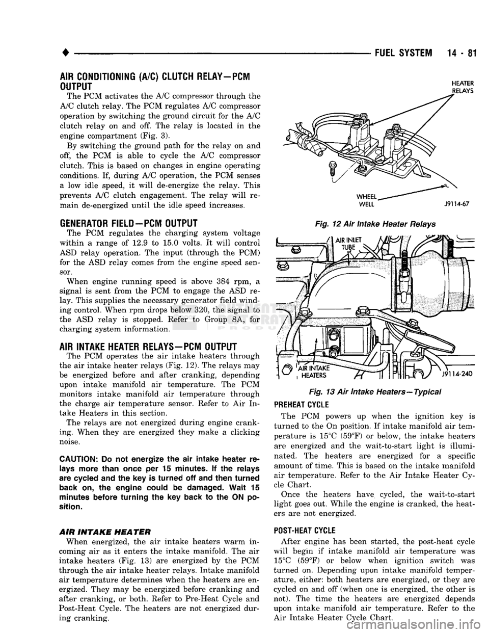
The PCM operates the air intake heaters through
the air intake heater relays (Fig. 12). The relays may
be energized before and after cranking, depending upon intake manifold air temperature. The PCM
monitors intake manifold air temperature through
the charge air temperature sensor. Refer to Air In
take Heaters in this section. The relays are not energized during engine crank
ing. When they are energized they make a clicking
noise.
CAUTION:
Do not energize the air intake heater re
lays
more than
once
per 15
minutes.
If the relays
are
cycled
and the key is turned off and then turned
back
on, the engine
could
be
damaged.
Wait 15
minutes
before
turning the key back to the ON po
sition.
AIR INTAKE
HEATER
When energized, the air intake heaters warm in
coming air as it enters the intake manifold. The air
intake heaters (Fig. 13) are energized by the PCM
through the air intake heater relays. Intake manifold air temperature determines when the heaters are en
ergized. They may be energized before cranking and
after cranking, or both. Refer to Pre-Heat Cycle and
Post-Heat Cycle. The heaters are not energized dur ing cranking.
HEATER
RELAYS
WELL
J9114-67
Fig.
12 Air Intake Heater
Relays
Fig.
13 Air Intake Heaters—Typical PREHEAT CYCLE
The PCM powers up when the ignition key is
turned to the On position. If intake manifold air tem
perature is 15°C (59°F) or below, the intake heaters are energized and the wait-to-start light is illumi
nated. The heaters are energized for a specific amount of time. This is based on the intake manifold
air temperature. Refer to the Air Intake Heater Cy
cle Chart.
Once the heaters have cycled, the wait-to-start
light goes out. While the engine is cranked, the heat
ers are not energized.
POST-HEAT CYCLE
After engine has been started, the post-heat cycle
will begin if intake manifold air temperature was 15°C (59°F) or below when ignition switch was
turned on. Depending upon intake manifold temper ature, either: both heaters are energized, or they are
cycled on and off (when one is energized, the other is
not).
The time the heaters are energized depends upon intake manifold air temperature. Refer to the
Air Intake Heater Cycle Chart.