steering FIAT 500E 2015 2.G Owner's Manual
[x] Cancel search | Manufacturer: FIAT, Model Year: 2015, Model line: 500E, Model: FIAT 500E 2015 2.GPages: 100, PDF Size: 2.97 MB
Page 51 of 100
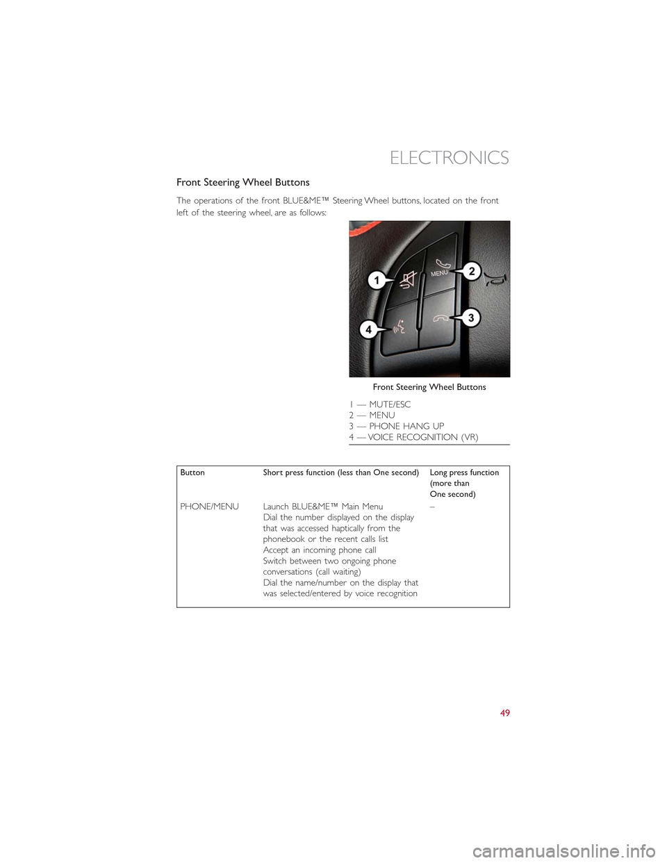
Front Steering Wheel Buttons
The operations of the front BLUE&ME™ Steering Wheel buttons, located on the front
left of the steering wheel, are as follows:
Button Short press function (less than One second) Long press function(more thanOne second)
PHONE/MENU Launch BLUE&ME™ Main MenuDial the number displayed on the displaythat was accessed haptically from thephonebook or the recent calls listAccept an incoming phone callSwitch between two ongoing phoneconversations (call waiting)Dial the name/number on the display thatwas selected/entered by voice recognition
–
Front Steering Wheel Buttons
1 — MUTE/ESC2 — MENU3 — PHONE HANG UP4 — VOICE RECOGNITION (VR)
ELECTRONICS
49
Page 52 of 100
Button Short press function (less than One second) Long press function(more thanOne second)
MUTE/ESC Cancel voice recognitionCancel a voice announcementInterrupt message readingExit BLUE&ME™ Main MenuExit the sub-menu and return to theprevious menu optionExit current menu option without storingsettingsTurn the microphone on/off during aphone conversationMute the ring tone of an incoming callMedia player Pause on/off
–
VOICE RECOGNI-TION (VR)Activate voice recognitionInterrupt voice announcement to provide anew voice command
Repeat the last ut-terance in a voiceinteraction
PHONE HANG UP Reject an incoming call and end a phonecall in progressEnd an active call and switch to a callwaiting (on hold)
–
PRESET UP/OK(center button onleft side back ofsteering wheel)
Confirm manually selected menu optionSwitch phone conversation from thehands-free phone to your mobile phoneand vice versaSelect displayed message
–
SCAN UP/SCANDOWN (upper andlower buttons onleft side back ofsteering wheel
Scroll BLUE&ME™ menu itemsScroll through media player tracksSeek up or down through radio stationsScroll inbox messages
–
Steering Wheel Audio Controls
•The right hand control on the rear of the steering wheel is a rocker type switch with
a pushbutton in the center.Push the switch up for Volume +.Push the switch down
for Volume –.The button in the center is the SRC button used to change audio
sources (e.g.AM, FM, CD, Media Player).
•The left hand control on the rear of the steering wheel is also a rocker type switch
with a pushbutton in the center.Push the top of the switch to Scan Up.Push the bot-
tom of the switch to Scan Down.The button in the center is the PRESET UP/OK
button.
ELECTRONICS
50
Page 53 of 100
BLUE&ME™ Hands-Free Communication
•To use the hands-free feature, you need a Bluetooth® wireless technology enabled
mobile phone.This hands-free feature gives you the possibility of interacting vocally
with your mobile phone while driving, even if your mobile device does not feature this
capability.You can also interact with your mobile phone manually and visually using the
steering wheel controls and the instrument panel Electronic Vehicle Information Center
(EVIC) display.
•To get started with BLUE&ME™ hands-free feature with voice recognition, you have to
simply pair your Bluetooth® wireless technology enabled mobile phone with the
system.
Pair Your Mobile Phone
•Push the VR button on the steering wheel then “Settings.” At the end of the
BLUE&ME™ message say “Pairing.” You may also access the pairing feature via the
menu by selecting it.
•The system will show the phone pairing PIN number on the EVIC display.For the next
two steps, consult your mobile phone owner’s manual about Bluetooth® pairing proce-
dures for your phone.
•On your mobile phone, search for devices equipped with Bluetooth® wireless technol-
ogy (the setting on your mobile phone might be called Discover or New Device).
In this list you will find BLUE&ME™ (name identifying the BLUE&ME™ system on
your car) select it.
•When prompted by the mobile phone, enter the PIN number shown on the instru-
ment panel display using your mobile phone keypad.If pairing is successful, the system
will say “Connecting” and at the end the display will show as confirmation message, the
ID of the paired mobile phone.
•It is essential to wait until you see this confirmation message on the display.Pushing
PHONE/MENU button on the steering wheel or MUTE/ESC button before the mes-
sage is displayed may cancel the pairing process.If the pairing process fails, an error
message will be displayed: in this event repeat the pairing procedure.
•At first pairing, BLUE&ME™ will say “Welcome” immediately after connecting.This
message will no longer be heard when your phone automatically connects to the
BLUE&ME™ system on future ignition cycles.
•BLUE&ME™ will ask if you would like to copy your paired phone phonebook to
BLUE&ME™.It is recommended to copy it.To start copying the phonebook say “Yes,”
otherwise say “No.”
ELECTRONICS
51
Page 54 of 100
•For certain mobile phones the phonebook is not copied automatically, in this case you
must transfer the phonebook contacts using your mobile phone keypad.If BLUE&ME™
asks you to do this, then perform this procedure following the instructions specific to your
mobile phone and push the PHONE/MENU button on the steering wheel when you have
finished.Certain mobile phones may require you to indicate that you do not want to be
asked every time to copy the phonebook.If this is the case, this could be indicated by
checking a box on the phone during the pairing process.If applicable, this option will only
be presented on the phone during the pairing process.
Making A Phone Call
•Assume that “John Smith” is one of the contacts stored in your phonebook.To call
John Smith, proceed as follows:
1.Push the VR steering wheel button and pronounce “Call John Smith.” If the name is
recognized, the system will display the recognized contact’s information on the display
screen.
2.If there is just one phone number for John Smith in your phonebook, the system will
ask if you would like to call John Smith.To start the call say “Yes,” otherwise say “No.”
If John Smith has several phone numbers, the system will ask which phone number
you would like to call (e.g.: “Call John Smith (at) Work or (at) Home?”).Answer with
the type of required phone number (e.g.: “(at) Home”).
3.If John Smith has several phone numbers but the “location” (e.g.: the type of phone
number like work, home, etc.) is missing, the system will display the selected contact
and a list of related phone numbers on the instrument cluster display.The hands-free
phone system will ask if you would like to call the phone number displayed.To re-
spond with “Yes,” pronounce “Yes,” otherwise say “No.” If this is the correct contact
but the wrong number, say “Forward” or “Backward” to navigate to the phone num-
ber you’d like to call.To call the displayed phone number, pronounce “Call.” You can
also scroll through the phone number list manually by pushing the buttons on the
back of the steering wheel until you find the required number.Then, push PRESET
UP/OK button on the rear of the steering wheel to start the call.
4.To end the phone call, push the PHONE HANG UP button on the steering wheel.
Media Player
•With the BLUE&ME™ media player you can play, via the car sound system, the digital
audio files stored on a USB device by simply connecting it to the USB port located on
the center console of the car.
•The MEDIA PLAYER menu enables the following:
– Display tracks stored on your USB stick/iPod®.
– Play audio files stored on your USB stick/iPod® (BLUE&ME™ recognizes.wma,.mp3
and.wav,.aac formats for audio files and.wpl and.m3u for playlists).
ELECTRONICS
52
Page 55 of 100
How To Connect The USB Stick/iPod® To BLUE&ME™
•To connect your USB stick/iPod® to BLUE&ME™, proceed as follows:
•USB devices without USB wire: just connect the USB stick/iPod® (directly or by an
extension lead) to the USB port on the car.
•USB stick/iPod® with USB wire: use the wire to connect the USB stick/iPod® to
the USB port on the car.
•Turn the ignition key to ON.BLUE&ME™ will start automatically to play your digital
tracks selecting them from the library built at the moment the USB stick/iPod® is
connected.
•If AUTOPLAY is set to “ON,” BLUE&ME™ will start playback automatically.
•Refer to the iPod®/USB/MP3 CONTROL section in this manual and the BLUE&ME™
User's Manual on the DVD for more details.
WARNING!
Driving while distracted can result in loss of vehicle control, accident and injury.It is
strongly recommended that you use extreme caution when using any device or feature
that may take your focus off the road or your hands off the steering wheel.Your pri-
mary responsibility is the safe operation of your vehicle.We recommend against the
use of any handheld device while driving, encourage the use of voice-operated systems
when possible and that you become aware of applicable laws that may affect the use of
electronic devices while driving.
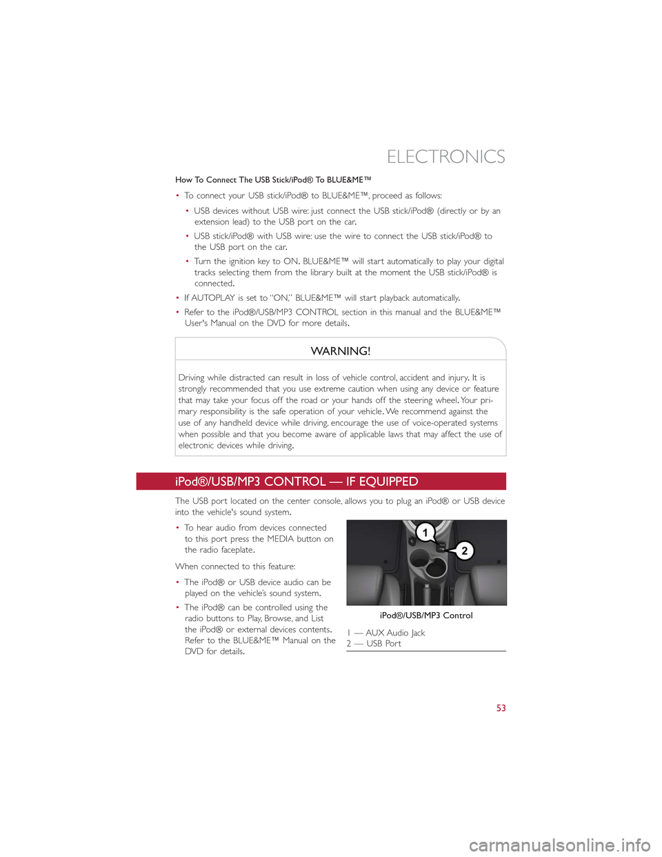
iPod®/USB/MP3 CONTROL — IF EQUIPPED
The USB port located on the center console, allows you to plug an iPod® or USB device
into the vehicle's sound system.
•To hear audio from devices connected
to this port press the MEDIA button on
the radio faceplate.
When connected to this feature:
•The iPod® or USB device audio can be
played on the vehicle’s sound system.
•The iPod® can be controlled using the
radio buttons to Play, Browse, and List
the iPod® or external devices contents.
Refer to the BLUE&ME™ Manual on the
DVD for details.
iPod®/USB/MP3 Control
1 — AUX Audio Jack2 — USB Port
ELECTRONICS
53
Page 58 of 100
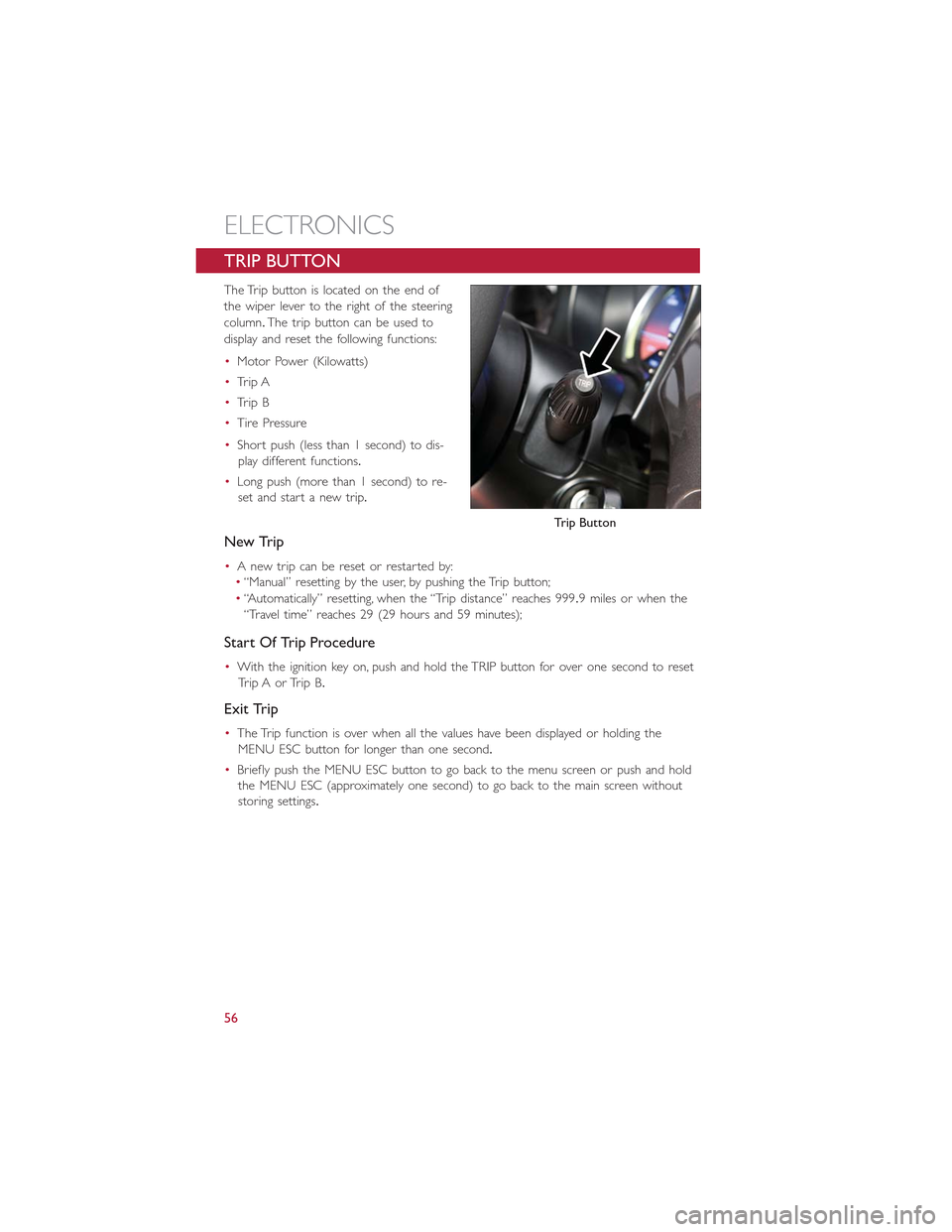
TRIP BUTTON
The Trip button is located on the end of
the wiper lever to the right of the steering
column.The trip button can be used to
display and reset the following functions:
•Motor Power (Kilowatts)
•Trip A
•Trip B
•Tire Pressure
•Short push (less than 1 second) to dis-
play different functions.
•Long push (more than 1 second) to re-
set and start a new trip.
New Trip
•A new trip can be reset or restarted by:
•“Manual” resetting by the user, by pushing the Trip button;
•“Automatically” resetting, when the “Trip distance” reaches 999.9 miles or when the
“Travel time” reaches 29 (29 hours and 59 minutes);
Start Of Trip Procedure
•With the ignition key on, push and hold the TRIP button for over one second to reset
Trip A or Trip B.
Exit Trip
•The Trip function is over when all the values have been displayed or holding the
MENU ESC button for longer than one second.
•Briefly push the MENU ESC button to go back to the menu screen or push and hold
the MENU ESC (approximately one second) to go back to the main screen without
storing settings.
Trip Button
ELECTRONICS
56
Page 62 of 100
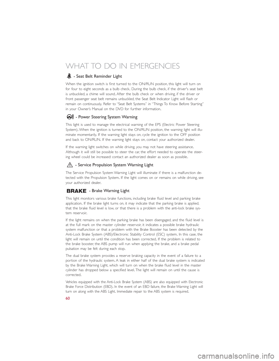
- Seat Belt Reminder Light
When the ignition switch is first turned to the ON/RUN position, this light will turn on
for four to eight seconds as a bulb check.During the bulb check, if the driver's seat belt
is unbuckled, a chime will sound.After the bulb check or when driving, if the driver or
front passenger seat belt remains unbuckled, the Seat Belt Indicator Light will flash or
remain on continuously.Refer to “Seat Belt Systems” in “Things To Know Before Starting”
in your Owner’s Manual on the DVD for further information.
- Power Steering System Warning
This light is used to manage the electrical warning of the EPS (Electric Power Steering
System).When the ignition is turned to the ON/RUN position, the warning light will illu-
minate momentarily.If the warning light stays on, cycle the ignition to the OFF position
and back to ON/RUN.If the warning light stays on, contact your authorized dealer.
If the warning light switches on while driving, you may not have steering assistance.
Although it will still be possible to steer the car, the effort needed to operate the steer-
ing wheel could be increased: contact an authorized dealer as soon as possible.
- Service Propulsion System Warning Light
The Service Propulsion System Warning Light will illuminate if there is a malfunction de-
tected with the Propulsion System.If the light comes on or remains on while driving, see
your authorized dealer.
- Brake Warning Light
This light monitors various brake functions, including brake fluid level and parking brake
application.If the brake light turns on, it may indicate that the parking brake is applied,
that the brake fluid level is low, or that there is a problem with the anti-lock brake sys-
tem reservoir.
If the light remains on when the parking brake has been disengaged, and the fluid level is
at the full mark on the master cylinder reservoir, it indicates a possible brake hydraulic
system malfunction or that a problem with the Brake Booster has been detected by the
Anti-Lock Brake System (ABS)/Electronic Stability Control (ESC) system.In this case, the
light will remain on until the condition has been corrected.If the problem is related to
the brake booster, the ABS pump will run when applying the brake, and a brake pedal
pulsation may be felt during each stop.
The dual brake system provides a reserve braking capacity in the event of a failure to a
portion of the hydraulic system.A leak in either half of the dual brake system is indicated
by the Brake Warning Light, which will turn on when the brake fluid level in the master
cylinder has dropped below a specified level.The light will remain on until the cause is
corrected.
Vehicles equipped with the Anti-Lock Brake System (ABS) are also equipped with Electronic
Brake Force Distribution (EBD).In the event of an EBD failure, the Brake Warning Light will
turn on along with the ABS Light.Immediate repair to the ABS system is required.
WHAT TO DO IN EMERGENCIES
60
Page 75 of 100
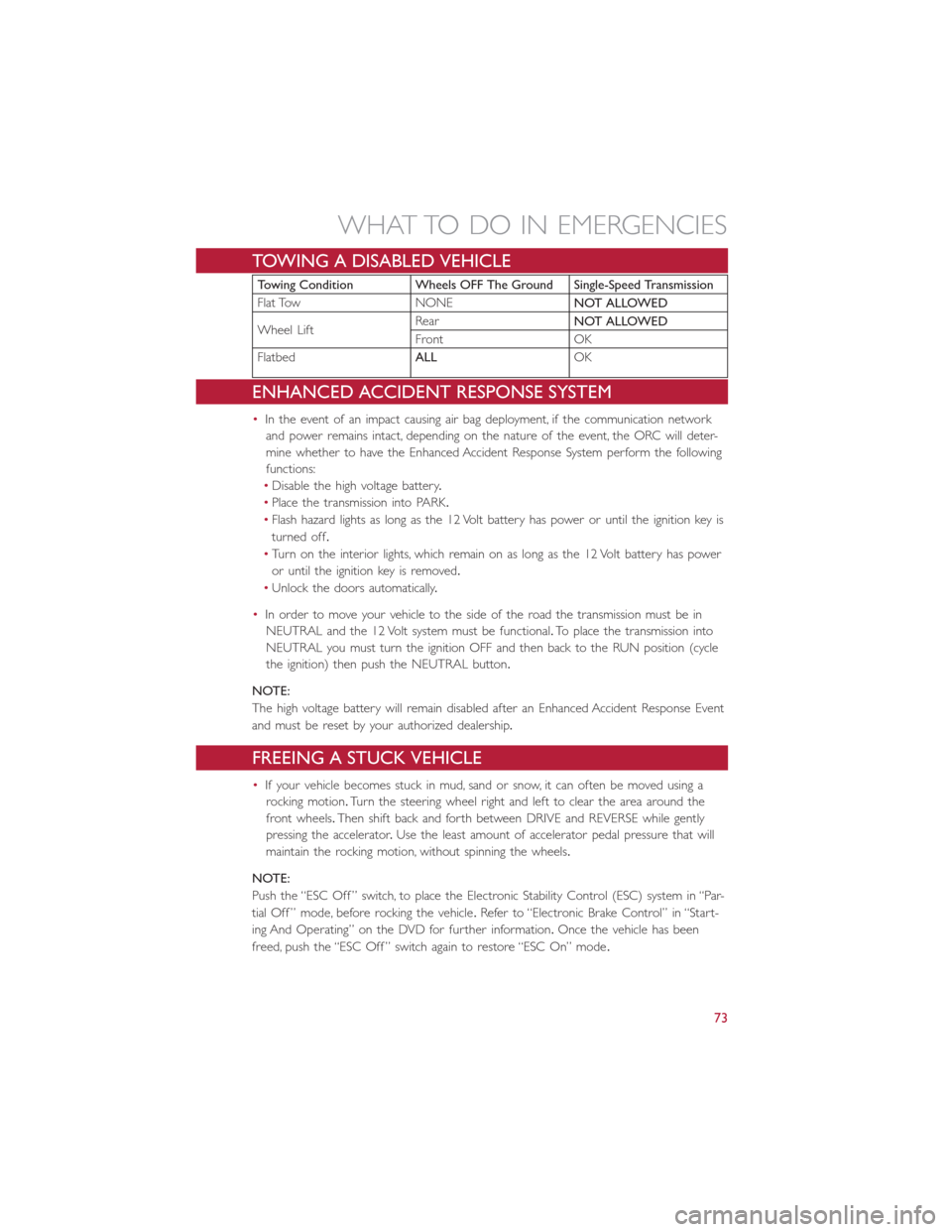
TOWING A DISABLED VEHICLE
Towing Condition Wheels OFF The Ground Single-Speed Transmission
Flat Tow NONENOT ALLOWED
Wheel LiftRearNOT ALLOWED
Front OK
FlatbedALLOK
ENHANCED ACCIDENT RESPONSE SYSTEM
•In the event of an impact causing air bag deployment, if the communication network
and power remains intact, depending on the nature of the event, the ORC will deter-
mine whether to have the Enhanced Accident Response System perform the following
functions:
•Disable the high voltage battery.
•Place the transmission into PARK.
•Flash hazard lights as long as the 12 Volt battery has power or until the ignition key is
turned off.
•Turn on the interior lights, which remain on as long as the 12 Volt battery has power
or until the ignition key is removed.
•Unlock the doors automatically.
•In order to move your vehicle to the side of the road the transmission must be in
NEUTRAL and the 12 Volt system must be functional.To place the transmission into
NEUTRAL you must turn the ignition OFF and then back to the RUN position (cycle
the ignition) then push the NEUTRAL button.
NOTE:
The high voltage battery will remain disabled after an Enhanced Accident Response Event
and must be reset by your authorized dealership.
FREEING A STUCK VEHICLE
•If your vehicle becomes stuck in mud, sand or snow, it can often be moved using a
rocking motion.Turn the steering wheel right and left to clear the area around the
front wheels.Then shift back and forth between DRIVE and REVERSE while gently
pressing the accelerator.Use the least amount of accelerator pedal pressure that will
maintain the rocking motion, without spinning the wheels.
NOTE:
Push the “ESC Off ” switch, to place the Electronic Stability Control (ESC) system in “Par-
tial Off ” mode, before rocking the vehicle.Refer to “Electronic Brake Control” in “Start-
ing And Operating” on the DVD for further information.Once the vehicle has been
freed, push the “ESC Off ” switch again to restore “ESC On” mode.
WHAT TO DO IN EMERGENCIES
73
Page 86 of 100
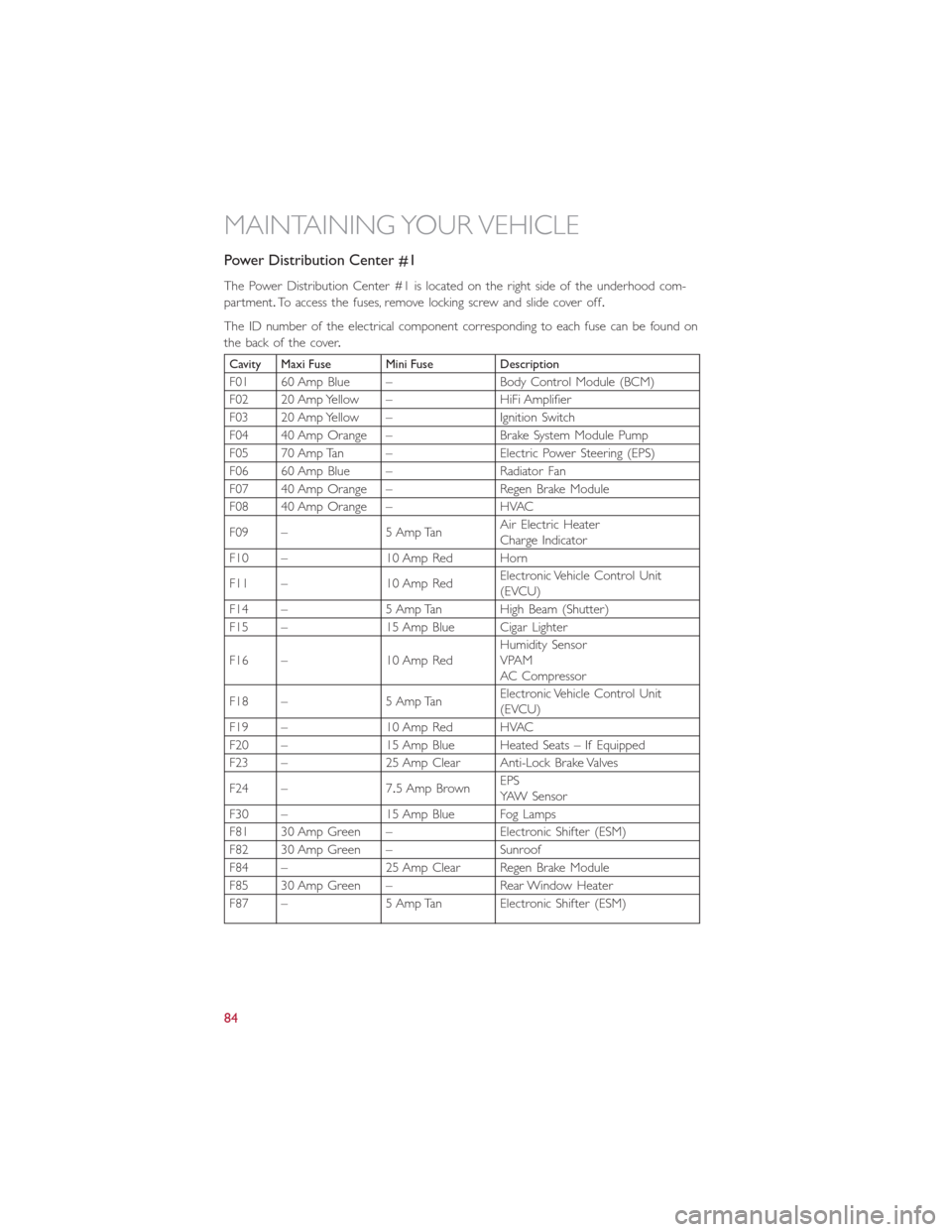
Power Distribution Center #1
The Power Distribution Center #1 is located on the right side of the underhood com-
partment.To access the fuses, remove locking screw and slide cover off.
The ID number of the electrical component corresponding to each fuse can be found on
the back of the cover.
Cavity Maxi Fuse Mini Fuse Description
F01 60 Amp Blue – Body Control Module (BCM)
F02 20 Amp Yellow – HiFi Amplifier
F03 20 Amp Yellow – Ignition Switch
F04 40 Amp Orange – Brake System Module Pump
F05 70 Amp Tan – Electric Power Steering (EPS)
F06 60 Amp Blue – Radiator Fan
F07 40 Amp Orange – Regen Brake Module
F08 40 Amp Orange – HVAC
F09 – 5 Amp TanAir Electric HeaterCharge Indicator
F10 – 10 Amp Red Horn
F11 – 10 Amp RedElectronic Vehicle Control Unit(EVCU)
F14 – 5 Amp Tan High Beam (Shutter)
F15 – 15 Amp Blue Cigar Lighter
F16 – 10 Amp RedHumidity SensorVPAMAC Compressor
F18 – 5 Amp TanElectronic Vehicle Control Unit(EVCU)
F19 – 10 Amp Red HVAC
F20 – 15 Amp Blue Heated Seats – If Equipped
F23 – 25 Amp Clear Anti-Lock Brake Valves
F24 – 7.5 Amp BrownEPSYAW Sensor
F30 – 15 Amp Blue Fog Lamps
F81 30 Amp Green – Electronic Shifter (ESM)
F82 30 Amp Green – Sunroof
F84 – 25 Amp Clear Regen Brake Module
F85 30 Amp Green – Rear Window Heater
F87 – 5 Amp Tan Electronic Shifter (ESM)
MAINTAINING YOUR VEHICLE
84
Page 88 of 100
WARNING!
•Overloading of your tires is dangerous.Overloading can cause tire failure, affect
vehicle handling, and increase your stopping distance.Use tires of the recom-
mended load capacity for your vehicle.Never overload them.
•Improperly inflated tires are dangerous and can cause collisions.Under-inflation is
the leading cause of tire failure and may result in severe cracking, component sepa-
ration, or “blow out”.Over-inflation reduces a tire’s ability to cushion shock.Ob-
jects on the road and chuck holes can cause damage that results in tire failure.
Unequal tire pressures can cause steering problems.You could lose control of your
vehicle.Over-inflated or under-inflated tires can affect vehicle handling and can fail
suddenly, resulting in loss of vehicle control.
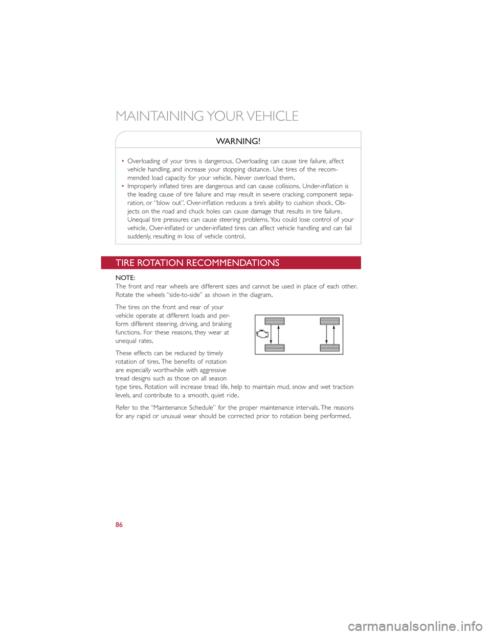
TIRE ROTATION RECOMMENDATIONS
NOTE:
The front and rear wheels are different sizes and cannot be used in place of each other.
Rotate the wheels “side-to-side” as shown in the diagram.
The tires on the front and rear of your
vehicle operate at different loads and per-
form different steering, driving, and braking
functions.For these reasons, they wear at
unequal rates.
These effects can be reduced by timely
rotation of tires.The benefits of rotation
are especially worthwhile with aggressive
tread designs such as those on all season
type tires.Rotation will increase tread life, help to maintain mud, snow and wet traction
levels, and contribute to a smooth, quiet ride.
Refer to the “Maintenance Schedule” for the proper maintenance intervals.The reasons
for any rapid or unusual wear should be corrected prior to rotation being performed.
MAINTAINING YOUR VEHICLE
86