engine FIAT 500L 2018 Owner handbook (in English)
[x] Cancel search | Manufacturer: FIAT, Model Year: 2018, Model line: 500L, Model: FIAT 500L 2018Pages: 268, PDF Size: 4.87 MB
Page 111 of 268
NOTE The engine can only be stopped
automatically after exceeding about
10 km/h, to prevent the engine from
being repeatedly stopped when driving
at walking pace.
The
warning light on the instrument
panel switches on to signal that the
engine has stopped.
Restarting the engine
Versions with manual transmission:
press the clutch pedal.
Versions with Dualogic
transmission: if the gear lever is in
position N (Neutral), place it in any other
gear, otherwise release the brake pedal
or move the gear lever to +, – or R.
MANUAL SYSTEM
ACTIVATION/
DEACTIVATION
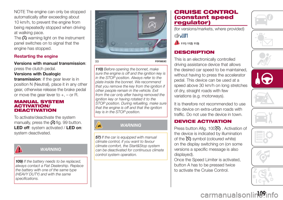
To activate/deactivate the system
manually, press the
fig. 99 button.
LED off: system activated /LED on:
system deactivated.
WARNING
109)If the battery needs to be replaced,
always contact a Fiat Dealership. Replace
the battery with one of the same type
(HEAVY DUTY) and with the same
specifications.110)Before opening the bonnet, make
sure the engine is off and the ignition key is
in the STOP position. Always refer to the
plate inside the bonnet. We recommend
that you remove the key from the ignition if
other people remain in the vehicle. Exit
from the car only after having removed the
ignition key or having rotated it to the
STOP position. During refuelling, make sure
that the engine is off and that the ignition
key is in the STOP position.
WARNING
57)If the car is equipped with manual
climate control, if you want to favour
climate comfort, the Start&Stop system
can be deactivated for continuous climate
control system operation.
CRUISE CONTROL
(constant speed
regulator)
(for versions/markets, where provided)
111) 112) 113)
DESCRIPTION
This is an electronically controlled
driving assistance device that allows
the desired car speed to be maintained,
without having to press the accelerator
pedal. This device can be used at a
speed above 30 km/h on long stretches
of dry, straight roads with few
variations (e.g. motorways).
It is therefore not recommended to use
this device on extra-urban roads with
traffic. Do not use the device in town.
DEVICE ACTIVATION
Press button Afig. 100
. Activation of
the device is indicated by illumination
of the
symbol (coloured white)
on the display switching on (on some
versions a specific message is also
displayed).
Once the Speed Limiter is activated,
button A has to be pressed twice
to activate the Cruise Control.
99F0Y0653C
109
Page 115 of 268
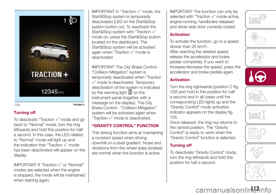
Turning off
To deactivate “Traction +” mode and go
back to “Normal” mode, turn the ring
leftwards and hold this position for half
a second. In this case, the LED related
to “Normal” mode will light up and
the indication that “Traction +” mode
has been deactivated will appear on the
display.
IMPORTANT If “Traction +” or “Normal”
modes are selected when the engine
is stopped, the mode will be maintained
when starting again.IMPORTANT In “Traction +” mode, the
Start&Stop system is temporarily
deactivated (LED on the Start&Stop
system button on). To reactivate the
Start&Stop system with “Traction +”
mode on, press the Start&Stop button
located on the dashboard. The
Start&Stop system will be activated
again when “Traction +” mode is
deactivated.
IMPORTANT The City Brake Control -
“Collision Mitigation” system is
temporarily deactivated when “Traction
+” mode is deactivated. Temporary
deactivation of the system is indicated
by the warning light
on the
instrument panel (together with a
message on the display). The City
Brake Control - “Collision Mitigation”
system will be activated again when
“Traction +” mode is deactivated.
“GRAVITY CONTROL” FUNCTION
This driving function aims at maintaining
a constant speed when driving
downhill on a steel gradient. Noise and
vibrations from the wheel sides (brakes)
are normal when the function is active.IMPORTANT The function can only be
selected with “Traction +” mode active,
engine running, handbrake released
and driver side door correctly closed.
Activation
To activate the function, go to a speed
slower than 25 km/h.
After reaching the desired speed,
release the accelerator and brake
pedals completely. If you want to
increase/decrease the speed, press the
accelerator and brake pedals again.
Activation
Turn the ring rightwards (position C fig.
102) and hold in this position for half
a second and in all cases until the
corresponding LED lights up and the
“Gravity Control” mode activation
indicator appears on the display fig.
105.
Once released, the ring-nut returns to
the central position. The “Gravity
Control” is ready to work when the
“Gravity Control” function is selected.
Turning off
To deactivate “Gravity Control” mode,
turn the ring leftwards and hold this
position for half a second.
104F0Y0667C
113
Page 116 of 268
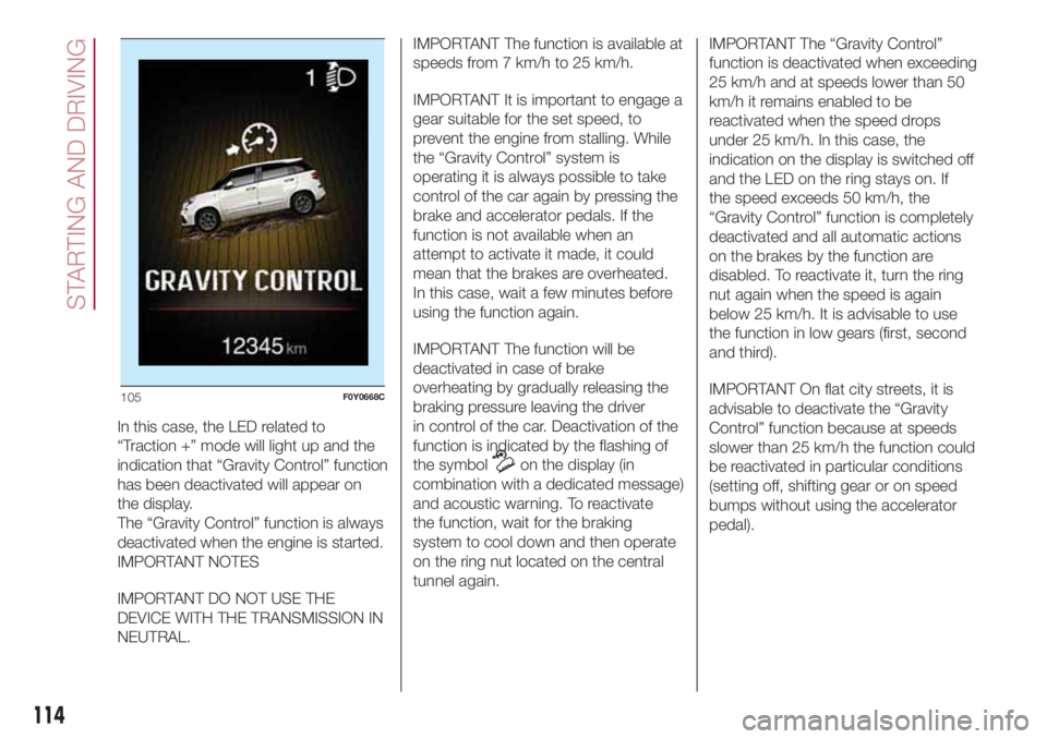
In this case, the LED related to
“Traction +” mode will light up and the
indication that “Gravity Control” function
has been deactivated will appear on
the display.
The “Gravity Control” function is always
deactivated when the engine is started.
IMPORTANT NOTES
IMPORTANT DO NOT USE THE
DEVICE WITH THE TRANSMISSION IN
NEUTRAL.IMPORTANT The function is available at
speeds from 7 km/h to 25 km/h.
IMPORTANT It is important to engage a
gear suitable for the set speed, to
prevent the engine from stalling. While
the “Gravity Control” system is
operating it is always possible to take
control of the car again by pressing the
brake and accelerator pedals. If the
function is not available when an
attempt to activate it made, it could
mean that the brakes are overheated.
In this case, wait a few minutes before
using the function again.
IMPORTANT The function will be
deactivated in case of brake
overheating by gradually releasing the
braking pressure leaving the driver
in control of the car. Deactivation of the
function is indicated by the flashing of
the symbol
on the display (in
combination with a dedicated message)
and acoustic warning. To reactivate
the function, wait for the braking
system to cool down and then operate
on the ring nut located on the central
tunnel again.IMPORTANT The “Gravity Control”
function is deactivated when exceeding
25 km/h and at speeds lower than 50
km/h it remains enabled to be
reactivated when the speed drops
under 25 km/h. In this case, the
indication on the display is switched off
and the LED on the ring stays on. If
the speed exceeds 50 km/h, the
“Gravity Control” function is completely
deactivated and all automatic actions
on the brakes by the function are
disabled. To reactivate it, turn the ring
nut again when the speed is again
below 25 km/h. It is advisable to use
the function in low gears (first, second
and third).
IMPORTANT On flat city streets, it is
advisable to deactivate the “Gravity
Control” function because at speeds
slower than 25 km/h the function could
be reactivated in particular conditions
(setting off, shifting gear or on speed
bumps without using the accelerator
pedal).
105F0Y0668C
114
STARTING AND DRIVING
Page 120 of 268
IMPORTANT NOTES
For towing caravans or trailers the car
must be fitted with an approved tow
hook and an adequate electrical
system. Installation must be carried out
by specialised technicians.
Install any specific and/or additional
door mirrors as specified by the
Highway Code.
Remember that, when towing a trailer,
steep hills are harder to climb, braking
distances increase and overtaking
takes longer depending on the overall
weight of the trailer.
Engage a low gear when driving
downhill, rather than constantly using
the brake.
The weight the trailer exerts on the car
tow hook reduces the car's loading
capacity by the same amount. To make
sure that the maximum towable weight
is not exceeded (given in the vehicle
registration document) account should
be taken of the fully laden trailer,
including accessories and luggage.
Do not exceed the speed limits specific
to each country you are driving in, in
the case of vehicles towing trailers.
In any case, the top speed must not
exceed 100 km/h.Any electric brake (or electric winch,
etc.) should be supplied directly by the
battery through a cable with a section
of at least 2.5 mm
2.
In addition to the electrical branches,
the car electrical system can only
be connected to the supply cable for an
electric brake and to the cable for an
internal light for the trailer, not
exceeding 15 W. For connections, use
the preset control unit with a battery
cable with section not less than 2.5
mm
2.
IMPORTANT The use of auxiliary loads
other than external lights (electric brake,
winch, etc.) must take place with
engine running.
IMPORTANT To install a tow hook
contact a Fiat Dealership.
WARNING
116)The ABS with which the car is
equipped will not control the braking
system of the trailer. Particular caution is
required on slippery roads.
117)Never modify the braking system of
the vehicle to control the trailer brake. The
trailer braking system must be fully
independent of the vehicle’s hydraulic
system.
118)After fitting, screw holes must be
sealed to prevent a exhaust gas inlet.
REFUELLING THE
VEHICLE
119) 120) 121)60)
Before refuelling, make sure that the
fuel type is correct. During refuelling
procedure, switch off the engine,
engage handbrake, rotate the ignition
key to STOP and do not smoke.
PETROL ENGINES
Only use unleaded petrol with a number
of octanes (R.O.N.) not lower than 95
(EN228 specification).
DIESEL ENGINES
Only use Diesel for motor vehicles
(EN590 specification).
When using or parking the car for a
long time in the mountains or cold
areas, it is advisable to refuel using
locally available Diesel. In this case, it is
also advisable to keep the tank over
50% full.
REFUELLING
PROCEDURE
Diesel and petrol versions
Proceed as follows:
open the flap A fig. 111 pulling
outwards, insert the nozzle in the filler
and refuel;
118
STARTING AND DRIVING
Page 123 of 268
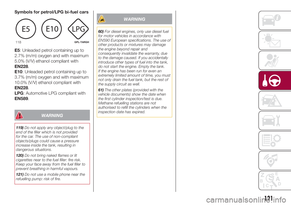
Symbols for petrol/LPG bi-fuel cars
E5: Unleaded petrol containing up to
2.7% (m/m) oxygen and with maximum
5.0% (V/V) ethanol compliant with
EN228.
E10: Unleaded petrol containing up to
3.7% (m/m) oxygen and with maximum
10.0% (V/V) ethanol compliant with
EN228.
LPG: Automotive LPG compliant with
EN589.
WARNING
119)Do not apply any object/plug to the
end of the filler which is not provided
for the car. The use of non-compliant
objects/plugs could cause a pressure
increase inside the tank, resulting in
dangerous situations.
120)Do not bring naked flames or lit
cigarettes near to the fuel filler: fire risk.
Keep your face away from the fuel filler to
prevent breathing in harmful vapours.
121)Do not use a mobile phone near the
refuelling pump: risk of fire.
WARNING
60)For diesel engines, only use diesel fuel
for motor vehicles in accordance with
EN590 European specifications. The use of
other products or mixtures may damage
the engine beyond repair and
consequently invalidate the warranty, due
to the damage caused. If you accidentally
introduce other types of fuel into the tank,
do not start the engine. Empty the tank.
If the engine has been run for even an
extremely limited amount of time, you must
not only drain the fuel tank, but the rest of
the supply circuit as well.
61)The other plates (provided with the
vehicle documents) show the date when
the first cylinder inspection/test is due.
Methane refuelling stations are not
authorised to refill the cylinders when the
inspection date has expired.
118GPL-TARGH
121
Page 125 of 268
HAZARD WARNING
LIGHTS
CONTROL
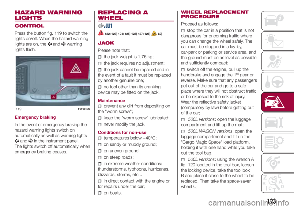
Press the button fig. 119 to switch the
lights on/off. When the hazard warning
lights are on, the
andwarning
lights flash.
Emergency braking
In the event of emergency braking the
hazard warning lights switch on
automatically as well as warning lights
andin the instrument panel.
The lights switch off automatically when
emergency braking ceases.
REPLACING A
WHEEL
122) 123) 124) 125) 128) 127) 126)62)
JACK
Please note that:
the jack weight is 1,76 kg;
the jack requires no adjustment;
the jack cannot be repaired and in
the event of a fault it must be replaced
by another genuine one;
no tool other than its cranking
device may be fitted on the jack.
Maintenance
prevent any dirt from depositing on
the "worm screw";
keep the "worm screw" lubricated;
never modify the jack.
Conditions for non-use
temperatures below −40°C;
on sandy or muddy ground;
on uneven ground;
on steep roads;
in extreme weather conditions:
thunderstorms, typhoons, hurricanes,
blizzards, storms, etc...
in direct contact with the engine or
for repairs under the car;
on boats.WHEEL REPLACEMENT
PROCEDURE
Proceed as follows:
stop the car in a position that is not
dangerous for oncoming traffic where
you can change the wheel safely. The
car must be stopped in a lay-by,
car-park or parking or service area, and
the ground must be as level as possible
and sufficiently compact;
switch off the engine, pull up the
handbrake and engage the 1stgear or
reverse. Make sure that any passengers
get out of the car and go to a safe
place where they will not obstruct traffic
or be exposed to the risk of injury.
Wear the reflective safety jacket
(compulsory by law) before getting out
of the car;
500L versions: open the luggage
compartment and lift up the mat;
500L WAGON versions: open the
luggage compartment and lift up the
"Cargo Magic Space" load platform,
holding it with one hand while you take
out the tool bag.
500L versions: using the wrench A
fig. 120 located in the tool box, loosen
the locking device, take the tool box
B and place it close to the wheel to be
replaced. Then take the space-saver
wheel C;
119F0Y0649C
123
Page 129 of 268
If you are on a slope or uneven surface,
place the wedge provided under the wheel
(see the instructions on the next pages).
124)The vehicle's driving characteristics
will be modified with the space-saver wheel
fitted. Avoid violent acceleration and
braking, abrupt steering and fast cornering.
The overall duration of the space-saver
wheel is of about 3000 km, after which the
relevant tyre must be replaced with another
one of the same type. Never install a
standard tyre on a rim that is designed for
use with a space-saver wheel. Have the
wheel repaired and refitted as soon as
possible. Using two or more space-saver
wheels at the same time is forbidden.
Do not grease the threads of the stud bolts
before fitting them: they might slip out.
125)The jack is a tool developed and
designed only for changing a wheel, if a
tyre gets punctured or damaged, on the
vehicle with which it is supplied or on other
vehicles of the same model. Any other
use, e.g. to jack up other vehicle models or
different things, is strictly prohibited. Never
use it to carry out maintenance or repairs
under the vehicle or to change summer/
winter wheels and vice versa: we advise
you to contact a Fiat Dealership. Never go
under the raised vehicle: use it only in
the positions indicated. Do not use the jack
for loads higher than the one shown on
its label. Never start the engine with car
raised. If the vehicle is raised more than
necessary, everything can become more
unstable, with the risk of the vehicle
dropping violently. Thus, lift the car only as
needed in order to access the space-saver
spare wheel.126)The space-saver wheel cannot be
fitted with snow chains. If a front (drive) tyre
is punctured and chains are needed, use
a standard wheel from the rear axle and
install the space-saver wheel on the rear
axle. In this way, with two normal drive
wheels at the front axle, it is possible to use
snow chains.
127)When turning the jack handle make
sure that it can turn freely without scraping
your hand against the ground. The moving
components of the jack ("worm screw"
and joints) can also cause injuries: do not
touch them. If you come into contact
with lubricating grease, clean yourself
thoroughly.
128)If the hub cap is not fitted correctly, it
may come off when the car is travelling.
Never tamper with the inflation valve. Never
introduce tools of any kind between rim
and tyre. Check tyre and space-saver
wheel pressures regularly, complying with
the values given in the "Technical
specifications" chapter.
129)At the end of the operation of
raising/locking the space-saver wheel
device, the spanner must be extracted,
taking care NOT to turn it in the wrong
direction to facilitate the extraction of the
spanner itself, so as to prevent the
attachment device from being released and
the lack of safe restraint.
WARNING
62)Contact a Fiat Dealership as soon as
possible to have the correct tightening
of the wheel stud bolts checked.
“Fix&Go Automatic”
KIT
130) 131)
63)2)
DESCRIPTION
The Fix&Go Automatic kit is located in
the boot, inside a dedicated container.
The container is also equipped with
a screwdriver, the tow hook and the
funnel for refuelling in an emergency. To
access the kit, open the boot door,
remove the load platform and lift the
covering carpet.
LPG versions
The kit is located in a bag fixed to the
boot lining by means of Velcro.
The kit fig. 130 contains:
one cartridge A containing sealant
and fitted with: transparent tube for
injecting the sealant 4 and sticker
C with the wording MAX 80 km/h / 50
mph to be placed in a clearly visible
position (e.g. on the dashboard) after
repairing the tyre;
a compressor B;
one leaflet containing instructions for
using the kit;
127
Page 130 of 268
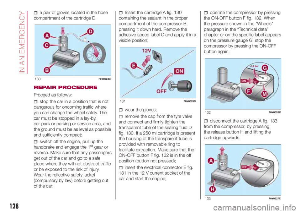
a pair of gloves located in the hose
compartment of the cartridge D.
REPAIR PROCEDURE
Proceed as follows:
stop the car in a position that is not
dangerous for oncoming traffic where
you can change the wheel safely. The
car must be stopped in a lay-by,
car-park or parking or service area, and
the ground must be as level as possible
and sufficiently compact;
switch off the engine, pull up the
handbrake and engage the 1stgear or
reverse. Make sure that any passengers
get out of the car and go to a safe
place where they will not obstruct traffic
or be exposed to the risk of injury.
Wear the reflective safety jacket
(compulsory by law) before getting out
of the car;
Insert the cartridge A fig. 130
containing the sealant in the proper
compartment of the compressor B,
pressing it down hard. Remove the
adhesive speed label C and apply it in a
visible position;
wear the gloves;
remove the cap from the tyre valve
and connect and firmly tighten the
transparent tube of the sealing fluid D
fig. 130. If a 250 ml cartridge is present
the housing of the transparent tube is
provided with removable ring to
facilitate extraction. Make sure that the
ON-OFF button F fig. 132 is in the off
position (button not pressed);
insert the electrical connector E fig.
131 in the 12 V current socket of the
car and start the engine;
operate the compressor by pressing
the ON-OFF button F fig. 132. When
the pressure shown in the "Wheels"
paragraph in the “Technical data”
chapter or on the specific label appears
on the pressure gauge G, stop the
compressor by pressing the ON-OFF
button again;
disconnect the cartridge A fig. 133
from the compressor, by pressing
the release button H and lifting the
cartridge upwards.
130F0Y0624C
131F0Y0625C
132F0Y0626C
133F0Y0627C
128
IN AN EMERGENCY
Page 139 of 268
WARNING
64)Halogen bulbs must be handled
holding the metallic part only. Touching the
transparent part of the bulb with your
fingers may reduce the intensity of the
emitted light and even reduce the lifespan
of the bulb. In the event of accidental
contact, wipe the bulb with a cloth
moistened with alcohol and let the bulb
dry.
65)Where possible, it is advisable to have
bulbs changed at a Fiat Dealership. The
correct operation and direction of the
external lights are absolutely essential for
the safety of the car and of compliance
with the law.
REPLACING FUSES
134) 135) 136) 137) 138) 139)66)
FUSE LOCATION
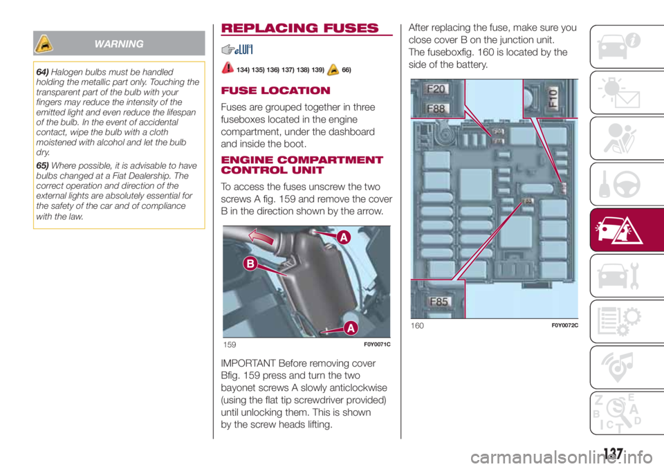
Fuses are grouped together in three
fuseboxes located in the engine
compartment, under the dashboard
and inside the boot.
ENGINE COMPARTMENT
CONTROL UNIT
To access the fuses unscrew the two
screws A fig. 159 and remove the cover
B in the direction shown by the arrow.
IMPORTANT Before removing cover
Bfig. 159 press and turn the two
bayonet screws A slowly anticlockwise
(using the flat tip screwdriver provided)
until unlocking them. This is shown
by the screw heads lifting.After replacing the fuse, make sure you
close cover B on the junction unit.
The fuseboxfig. 160 is located by the
side of the battery.
159F0Y0071C
160F0Y0072C
137
Page 143 of 268
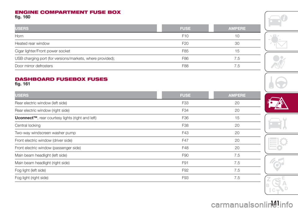
ENGINE COMPARTMENT FUSE BOX
fig. 160
USERSFUSE AMPERE
HornF10 10
Heated rear windowF20 30
Cigar lighter/Front power socket F85 15
USB charging port (for versions/markets, where provided); F86 7.5
Door mirror defrostersF88 7.5
DASHBOARD FUSEBOX FUSES
fig. 161
USERSFUSE AMPERE
Rear electric window (left side) F33 20
Rear electric window (right side) F34 20
Uconnect™, rear courtesy lights (right and left) F36 15
Central lockingF38 20
Two-way windscreen washer pump F43 20
Front electric window (driver side) F47 20
Front electric window (passenger side) F48 20
Main beam headlight (left side) F90 7.5
Main beam headlight (right side) F91 7.5
Fog light (left side)F92 7.5
Fog light (right side)F93 7.5
141