FIAT BRAVO 2007 2.G Manual Online
Manufacturer: FIAT, Model Year: 2007, Model line: BRAVO, Model: FIAT BRAVO 2007 2.GPages: 246, PDF Size: 3.75 MB
Page 81 of 246
80
SAFETY
DEVICES
CORRECT USE
OF THE CAR
WARNING
LIGHTS AND
MESSAGES
IN AN
EMERGENCY
CAR
MAINTENANCE
TECHNICAL
SPECIFICATIONS
INDEX
DASHBOARD
AND CONTROLS
EXTENDING THE BOOT
The boot can be partially (1/3 or 2/3) or
totally extended splitting the rear seat.
Partial extension
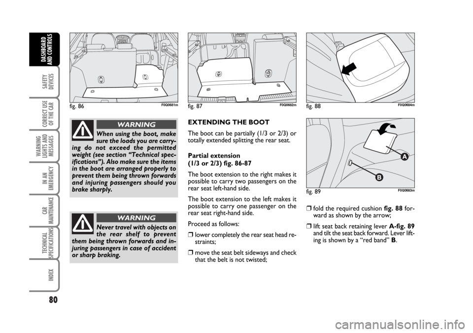
(1/3 or 2/3) fig. 86-87
The boot extension to the right makes it
possible to carry two passengers on the
rear seat left-hand side.
The boot extension to the left makes it
possible to carry one passenger on the
rear seat right-hand side.
Proceed as follows:
❒lower completely the rear seat head re-
straints;
❒move the seat belt sideways and check
that the belt is not twisted;
❒fold the required cushion fig. 88for-
ward as shown by the arrow;
❒lift seat back retaining lever A-fig. 89
and tilt the seat back forward. Lever lift-
ing is shown by a “red band” B.
When using the boot, make
sure the loads you are carry-
ing do not exceed the permitted
weight (see section “Technical spec-
ifications”). Also make sure the items
in the boot are arranged properly to
prevent them being thrown forwards
and injuring passengers should you
brake sharply.
WARNING
Never travel with objects on
the rear shelf to prevent
them being thrown forwards and in-
juring passengers in case of accident
or sharp braking.
WARNING
fig. 86F0Q0681mfig. 87F0Q0682mfig. 88F0Q0684m
fig. 89F0Q0683m
057-082 BRAVO GB 10-05-2007 9:09 Pagina 80
Page 82 of 246
TO RETURN THE REAR SEAT
BACK TO ITS ORIGINAL
POSITION
Move aside the seat belts, check that they
are not twisted.
Lift the seat backs and push them back-
ward until both coupling mechanisms click
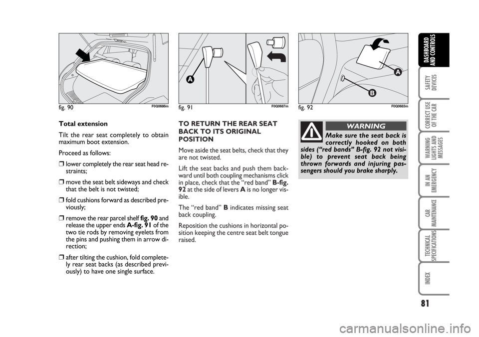
in place, check that the “red band” B-fig.
92at the side of levers Ais no longer vis-
ible.
The “red band” Bindicates missing seat
back coupling.
Reposition the cushions in horizontal po-
sition keeping the centre seat belt tongue
raised.
81
SAFETY
DEVICES
CORRECT USE
OF THE CAR
WARNING
LIGHTS AND
MESSAGES
IN AN
EMERGENCY
CAR
MAINTENANCE
TECHNICAL
SPECIFICATIONS
INDEX
DASHBOARD
AND CONTROLS
Total extension
Tilt the rear seat completely to obtain
maximum boot extension.
Proceed as follows:
❒lower completely the rear seat head re-
straints;
❒move the seat belt sideways and check
that the belt is not twisted;
❒fold cushions forward as described pre-
viously;
❒remove the rear parcel shelf fig. 90and
release the upper ends A-fig. 91of the
two tie rods by removing eyelets from
the pins and pushing them in arrow di-
rection;
❒after tilting the cushion, fold complete-
ly rear seat backs (as described previ-
ously) to have one single surface.
fig. 91F0Q0687mfig. 90F0Q0686mfig. 92F0Q0683m
Make sure the seat back is
correctly hooked on both
sides (“red bands” B-fig. 92 not visi-
ble) to prevent seat back being
thrown forwards and injuring pas-
sengers should you brake sharply.
WARNING
057-082 BRAVO GB 10-05-2007 9:09 Pagina 81
Page 83 of 246
82
SAFETY
DEVICES
CORRECT USE
OF THE CAR
WARNING
LIGHTS AND
MESSAGES
IN AN
EMERGENCY
CAR
MAINTENANCE
TECHNICAL
SPECIFICATIONS
INDEX
DASHBOARD
AND CONTROLS
ANCHORING THE LOAD
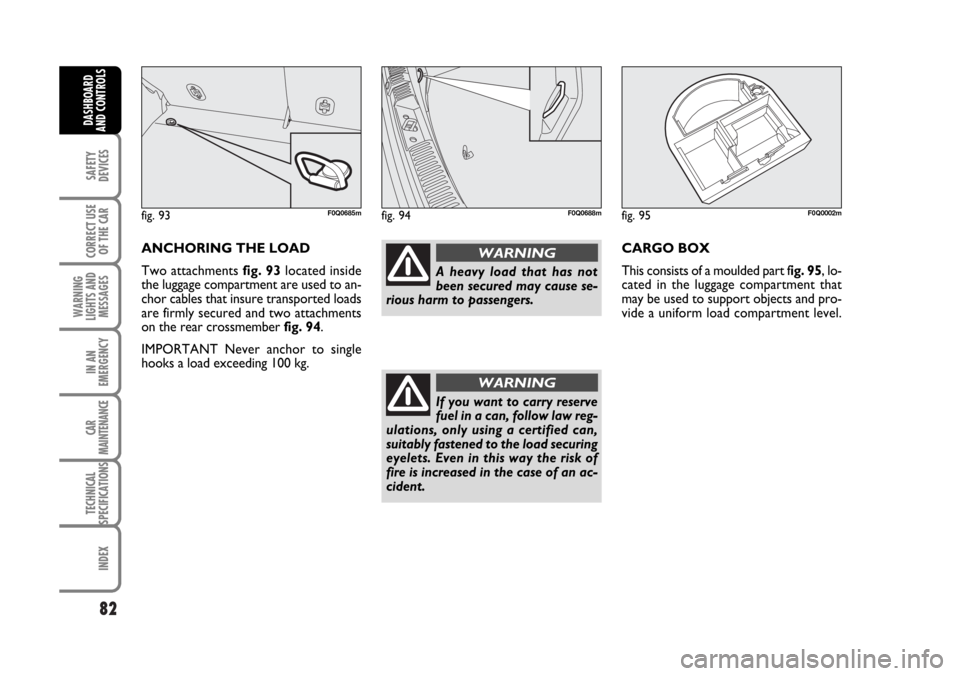
Two attachments fig. 93located inside
the luggage compartment are used to an-
chor cables that insure transported loads
are firmly secured and two attachments
on the rear crossmember fig. 94.
IMPORTANT Never anchor to single
hooks a load exceeding 100 kg.
A heavy load that has not
been secured may cause se-
rious harm to passengers.
WARNING
If you want to carry reserve
fuel in a can, follow law reg-
ulations, only using a certified can,
suitably fastened to the load securing
eyelets. Even in this way the risk of
fire is increased in the case of an ac-
cident.
WARNING
fig. 93F0Q0685mfig. 94F0Q0688mfig. 95F0Q0002m
CARGO BOX
This consists of a moulded part fig. 95, lo-
cated in the luggage compartment that
may be used to support objects and pro-
vide a uniform load compartment level.
057-082 BRAVO GB 10-05-2007 9:09 Pagina 82
Page 84 of 246
83
SAFETY
DEVICES
CORRECT USE
OF THE CAR
WARNING
LIGHTS AND
MESSAGES
IN AN
EMERGENCY
CAR
MAINTENANCE
TECHNICAL
SPECIFICATIONS
INDEX
DASHBOARD
AND CONTROLS
BONNET
TO OPEN THE BONNET
Proceed as follows:
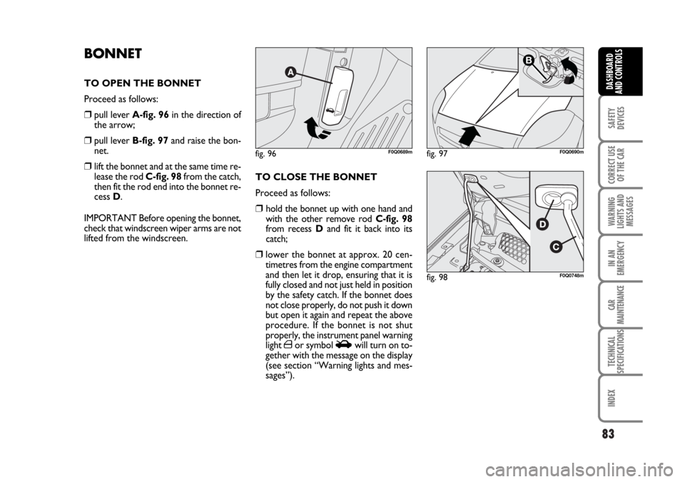
❒pull lever A-fig. 96in the direction of
the arrow;
❒pull lever B-fig. 97and raise the bon-
net.
❒lift the bonnet and at the same time re-
lease the rod C-fig. 98from the catch,
then fit the rod end into the bonnet re-
cess D.
IMPORTANT Before opening the bonnet,
check that windscreen wiper arms are not
lifted from the windscreen.TO CLOSE THE BONNET
Proceed as follows:
❒hold the bonnet up with one hand and
with the other remove rod C-fig. 98
from recess Dand fit it back into its
catch;
❒lower the bonnet at approx. 20 cen-
timetres from the engine compartment
and then let it drop, ensuring that it is
fully closed and not just held in position
by the safety catch. If the bonnet does
not close properly, do not push it down
but open it again and repeat the above
procedure. If the bonnet is not shut
properly, the instrument panel warning
light ´or symbol Swill turn on to-
gether with the message on the display
(see section “Warning lights and mes-
sages”).
fig. 96F0Q0689mfig. 97
B
F0Q0690m
fig. 98F0Q0748m
083-104 BRAVO GB 10-05-2007 9:10 Pagina 83
Page 85 of 246
84
SAFETY
DEVICES
CORRECT USE
OF THE CAR
WARNING
LIGHTS AND
MESSAGES
IN AN
EMERGENCY
CAR
MAINTENANCE
TECHNICAL
SPECIFICATIONS
INDEX
DASHBOARD
AND CONTROLS
ROOF RACK/SKI RACK
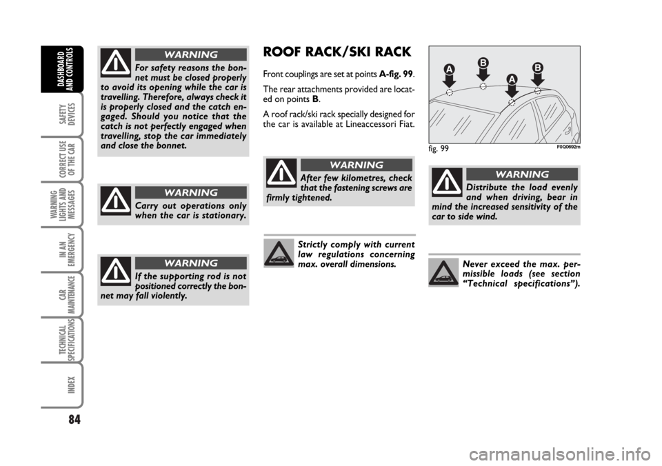
Front couplings are set at points A-fig. 99.
The rear attachments provided are locat-
ed on points B.
A roof rack/ski rack specially designed for
the car is available at Lineaccessori Fiat.
fig. 99F0Q0692m
After few kilometres, check
that the fastening screws are
firmly tightened.
WARNING
Strictly comply with current
law regulations concerning
max. overall dimensions.
Distribute the load evenly
and when driving, bear in
mind the increased sensitivity of the
car to side wind.
WARNING
Never exceed the max. per-
missible loads (see section
“Technical specifications”).
For safety reasons the bon-
net must be closed properly
to avoid its opening while the car is
travelling. Therefore, always check it
is properly closed and the catch en-
gaged. Should you notice that the
catch is not perfectly engaged when
travelling, stop the car immediately
and close the bonnet.
WARNING
Carry out operations only
when the car is stationary.
WARNING
If the supporting rod is not
positioned correctly the bon-
net may fall violently.
WARNING
083-104 BRAVO GB 10-05-2007 9:10 Pagina 84
Page 86 of 246
HEADLIGHTS
ADJUSTING THE
HEADLIGHT BEAM
Proper adjustment of the headlight beams
is of vital importance for your safety and
comfort and also for the other road users.
To ensure you and other drivers have the
best visibility conditions when travelling
with the headlights on, the headlights must
be set properly. Contact Fiat Dealership
to have the headlights properly adjusted.
IMPORTANT When turning on gas dis-
charge headlight lamps (where provided),
it is normal that there should be a vertical
movement of lenses, and consequently the
same will also happen to the light beam,
for the time required to achieve the cor-
rect headlight trim stabilisation, equal to
approx. 2 seconds.
HEADLIGHT AIMING DEVICE
This device can be operated with the ig-
nition key at MARand dipped beams on.
When the car is loaded, it slopes back-
wards. This means that the headlight beam
rises. In this case, it is necessary to return
it to the correct position.
85
SAFETY
DEVICES
CORRECT USE
OF THE CAR
WARNING
LIGHTS AND
MESSAGES
IN AN
EMERGENCY
CAR
MAINTENANCE
TECHNICAL
SPECIFICATIONS
INDEX
DASHBOARD
AND CONTROLS
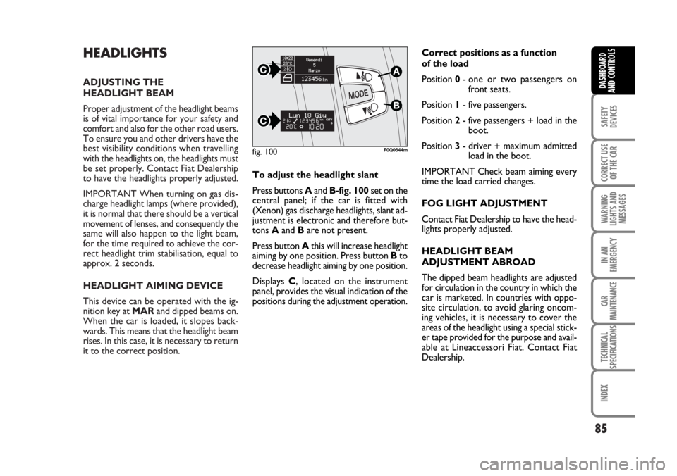
To adjust the headlight slant
Press buttons Aand B-fig. 100set on the
central panel; if the car is fitted with
(Xenon) gas discharge headlights, slant ad-
justment is electronic and therefore but-
tons Aand Bare not present.
Press button Athis will increase headlight
aiming by one position. Press button Bto
decrease headlight aiming by one position.
Displays C, located on the instrument
panel, provides the visual indication of the
positions during the adjustment operation.Correct positions as a function
of the load
Position 0- one or two passengers on
front seats.
Position 1- five passengers.
Position 2- five passengers + load in the
boot.
Position 3- driver + maximum admitted
load in the boot.
IMPORTANT Check beam aiming every
time the load carried changes.
FOG LIGHT ADJUSTMENT
Contact Fiat Dealership to have the head-
lights properly adjusted.
HEADLIGHT BEAM
ADJUSTMENT ABROAD
The dipped beam headlights are adjusted
for circulation in the country in which the
car is marketed. In countries with oppo-
site circulation, to avoid glaring oncom-
ing vehicles, it is necessary to cover the
areas of the headlight using a special stick-
er tape provided for the purpose and avail-
able at Lineaccessori Fiat. Contact Fiat
Dealership.
fig. 100F0Q0644m
083-104 BRAVO GB 10-05-2007 9:10 Pagina 85
Page 87 of 246
86
SAFETY
DEVICES
CORRECT USE
OF THE CAR
WARNING
LIGHTS AND
MESSAGES
IN AN
EMERGENCY
CAR
MAINTENANCE
TECHNICAL
SPECIFICATIONS
INDEX
DASHBOARD
AND CONTROLS
When the ABS cuts in, and
you feel the brake pedal pul-
sating, do not remove your foot, but
keep it pressed; in doing so you will
stop in the shortest amount of space
possible under the current road con-
ditions.
WARNING
The ABS exploits the tyre-
road grip at the best, but it
cannot improve it; you should there-
fore take every care when driving on
slippery surfaces without taking un-
necessary risks.
WARNINGABS SYSTEM
The car is fitted with ABS braking system,
which prevents the wheels from locking
when braking, makes the most of road grip
and gives the best control when emer-
gency braking under difficult road condi-
tions.
System is completed by EBD (Electronic
Braking Force Distribution), which dis-
tributes the braking action between front
and rear wheels.
IMPORTANT To have the maximum ef-
ficiency of the braking system, it is neces-
sary a setting period of about 500 km: dur-
ing this period, it is better to avoid sharp,
repeated and prolonged brakes.ABS SYSTEM INTERVENTION
The driver can tell the ABS system has
come into action because the brake ped-
al pulsates slightly and the system gets
noisier: it means that the car speed should
be altered to fit the type of road surface.
If the ABS system cuts in it
is a sign that the grip be-
tween the tyre and the road surface
has reached the limit you must slow
down to match the speed to the road
grip available.
WARNING
083-104 BRAVO GB 10-05-2007 9:10 Pagina 86
Page 88 of 246
87
SAFETY
DEVICES
CORRECT USE
OF THE CAR
WARNING
LIGHTS AND
MESSAGES
IN AN
EMERGENCY
CAR
MAINTENANCE
TECHNICAL
SPECIFICATIONS
INDEX
DASHBOARD
AND CONTROLS
FAILURE INDICATIONS
ABS failure
ABS failure is indicated by the turning on
of warning light
>on the instrument pan-
el (together with the dedicated message
on the display) (see section “Warning
lights and messages”). In this case the
braking system is still efficient, though
without the aid of the ABS system. Drive
carefully to the closest Fiat Dealership to
have the system checked.EBD failure
EBD failure is indicated by the turning on
of warning lights
>and xon the in-
strument panel (together with the mes-
sage on the display) (see section “Warn-
ing lights and messages”).
In this case with sharp braking the rear
wheels might lock too early, with the pos-
sibility of skidding. Drive extremely care-
fully to the nearest Fiat Dealership to have
the system checked.
If the instrument panel
warning light xturns on
(together with the message on the dis-
play), stop the car immediately and
contact the nearest Fiat Dealership.
Fluid leaks from the hydraulic system,
in fact, can compromise the braking
system, both traditional systems and
systems with ABS.
WARNING
BRAKE ASSIST
(emergency braking assistance)
(where provided)
The system, which cannot be cut out, rec-
ognizes emergency braking (on the ground
of the brake pedal operation speed) and
considerably increases the pressure in the
braking circuit.
Brake Assist is deactivated on versions
equipped with ESP, in the event of ESP sys-
tem failure (indicated by warning light
áturning on together with the message on
the display).
083-104 BRAVO GB 10-05-2007 9:10 Pagina 87
Page 89 of 246
88
SAFETY
DEVICES
CORRECT USE
OF THE CAR
WARNING
LIGHTS AND
MESSAGES
IN AN
EMERGENCY
CAR
MAINTENANCE
TECHNICAL
SPECIFICATIONS
INDEX
DASHBOARD
AND CONTROLS
ESP SYSTEM
(Electronic Stability
Program)
(where provided)
The ESP system is an electronic system
controlling the car stability in the event of
tyre grip loss.
The ESP system is therefore particularly
useful when grip conditions of the road
surfaces changes.
With ESP, ASR and Hill Holder systems
is also installed (where provided) the MSR
system (engine brake torque control sys-
tem).
ESP SYSTEM INTERVENTION
It is signalled by the blinking of the warn-
ing light
áon the instrument panel, to in-
form the driver that the car is in critical
stability and grip conditions.HILL HOLDER SYSTEM
This system is an integral part of the ESP
system and it is provided to facilitate start-
ing on slopes.
It will activate automatically with the fol-
lowing conditions:
❒Uphill: car at a standstill on a road with
a gradient higher than 5%, engine run-
ning, clutch and brake pedal pressed,
gearbox to neutral or engaged gear oth-
er than reverse.
❒Downhill: car at a standstill on a road
with a gradient higher than 5%, engine
running, clutch and brake pedal pressed
and reverse gear engaged.
At pickup the ESP system control unit will
keep brake force on wheels until reaching
the torque suitable for starting, or in any
case for max. 2 seconds in order to pass
easily from the brake pedal to the accel-
erator pedal.
After two seconds without starting, the
system will deactivate automatically by re-
leasing gradually the brake force.
At releasing, the typical brake disengage-
ment noise indicating that the car is go-
ing to move will be heard.
Performance of the ESP sys-
tem, in terms of active safe-
ty should not induce the driver to take
pointless and unnecessary risks. The
style of driving must in any case al-
ways be adapted to the conditions of
the road surface, visibility an traffic.
Road safety is always the driver’s re-
sponsibility.
WARNING
ESP SYSTEM ACTIVATION
The ESP system is automatically activat-
ed when the car is started and cannot be
de-activated.
FAILURE INDICATIONS
In the event of failure, the ESP system is
automatically disconnected and the warn-
ing light
ácomes on with fixed light on
the instrument panel (on certain versions
together with the message on the display)
(see section “Warning lights and mes-
sages”). In this case contact a Fiat Deal-
ership as soon as possible.
083-104 BRAVO GB 10-05-2007 9:10 Pagina 88
Page 90 of 246
89
SAFETY
DEVICES
CORRECT USE
OF THE CAR
WARNING
LIGHTS AND
MESSAGES
IN AN
EMERGENCY
CAR
MAINTENANCE
TECHNICAL
SPECIFICATIONS
INDEX
DASHBOARD
AND CONTROLS
During the use of the space-
saver spare wheel, the ESP
system carries on working. However,
you must remind that the space-saver
spare wheel has dimensions smaller
than the standard tyre and therefore
its grip is reduced as to the other car
tyres.
WARNING
FAILURE INDICATIONS
System failure is indicated by the turning
on of warning light
áon the instrument
panel (together with the message on the
display) (see section “Warning lights and
messages”).
IMPORTANT The Hill Holder system is
not a parking brake. Never get out of the
car without engaging the handbrake,
switching the engine off and engaging the
first gear.
For correct operation of the
ESP and ASR systems, the
tyres must absolutely be of the same
brand and type on all wheels, in per-
fect conditions and, above all, of
type, brand and size specified.
WARNING
ASR SYSTEM
(Antislip Regulation)
It is an integral part of the ESP system, it
controls car drive and cuts in automati-
cally every time one or both driving
wheels slip.
According to slipping conditions, two dif-
ferent control systems are activated:
❒if the slipping involves both the driving
wheels, the ASR function intervenes re-
ducing the power transmitted by the
engine;
❒if the slipping involves only one driving
wheel, the ASR system cuts in auto-
matically braking the wheel that is slip-
ping.
The action of the ASR is particularly help-
ful in the following circumstances:
❒slipping of the inner wheel due to the
effect of dynamic load changes or ex-
cessive acceleration;
❒too much power transmitted to the
wheels also in relation to the conditions
of the road surface;
❒acceleration on slippery, snowy or
frozen surfaces;
❒in the case of loss of grip on a wet sur-
face (aquaplaning).Switching the ASR system on/off
The ASR system switches on automatically
each time the engine is started.
Switching on/off is indicated by the rele-
vant message on the display (see section
“Warning lights and messages”).
The performance of the sys-
tem, in terms of active safe-
ty should not induce the driver to take
pointless and unnecessary risks. The
style of driving must in any case al-
ways be adapted to the conditions of
the road surface, visibility and traffic.
Road safety is always the driver’s re-
sponsibility.
WARNING
083-104 BRAVO GB 10-05-2007 9:10 Pagina 89