change time FIAT DOBLO PANORAMA 2017 2.G Owners Manual
[x] Cancel search | Manufacturer: FIAT, Model Year: 2017, Model line: DOBLO PANORAMA, Model: FIAT DOBLO PANORAMA 2017 2.GPages: 298, PDF Size: 26.04 MB
Page 8 of 298
IMPORTANT
This Owner Handbook describes all Fiat Doblò versions. Options, equipment dedicated to specific markets or
versions are not explicitly indicated in the text: as a consequence, you should only consider the information which
is related to the trim level, engine and version that you have purchased. Any content introduced throughout the
production of the model, outside the explicit request of options at the time of purchase, will be identified with the
wording(for versions/markets, where provided).
All data contained in this publication are intended to help you use your vehicle in the best possible way. Fiat aims
at a constant improvement of the vehicles produced. For this reason it reserves the right to make changes to
the model described for technical and/or commercial reasons.
For further information, contact a Fiat Dealership.
SYMBOLS
Some vehicle components have coloured labels whose symbols indicate precautions to be observed when using this
component.
A plate summarising these symbols can also be found under the bonnet.
Page 21 of 298
7)It is absolutely forbidden to carry out any
after-market operation involving steering
system or steering column modifications
(e.g.: installation of anti-theft device) that
could badly affect performance and safety,
cause the lapse of warranty and also
result in non-compliance of the vehicle with
type approval requirements.SYMBOLS
Some vehicle components have
coloured labels whose symbols indicate
precautions to be observed when
using this component. Under the
bonnet there is also a label that
summarises all the symbols.
THE FIAT CODE
SYSTEM
IN BRIEF
This is an electrical engine locking
system which increases protection
against attempted theft of the vehicle.
It is automatically activated when
the ignition key is removed.
Each key contains an electronic
device which modulates the signal
emitted during ignition by an antenna
built into the ignition device. The
signal, which changes each time the
engine is started, is the “password”,
by means of which the control unit
recognises the key and enables
starting.
1)
Operation
Each time the vehicle is started turning
the ignition key toMAR, the Fiat CODE
system control unit sends a recognition
code to the Powertrain Control Module
to deactivate the inhibitor.
The acknowledgement code is sent
only if the Fiat CODE system control
unit has recognised the code
transmitted from the key.
17
Page 37 of 298
MAIN BEAM HEADLIGHTS
With ring nut in position
, push the
stalk forward toward the dashboard
(stable position). The
warning light
switches on in the instrument panel.
Pulling the stalk towards the steering
wheel, the main beams are turned
off and the dipped headlights on.
FLASHING
You can flash the beams pulling the
stalk toward the steering wheel
(unstable position). The
warning
light switches on in the instrument
panel.
DIRECTION INDICATORS
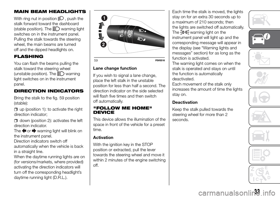
Bring the stalk to the fig. 59 position
(stable):
up (position 1): to activate the right
direction indicator;
down (position 2): activates the left
direction indicator.
The
orwarning light will blink on
the instrument panel.
Direction indicators switch off
automatically when the vehicle is back
in a straight line.
When the daytime running lights are on
(for versions/markets, where provided)
activating the direction indicators will
turn off the corresponding headlight’s
daytime running light (D.R.L.).Lane change function
If you wish to signal a lane change,
place the left stalk in the unstable
position for less than half a second. The
direction indicator on the side selected
will flash five times and then switch
off automatically.
"FOLLOW ME HOME"
DEVICE
This device allows the illumination of the
space in front of the vehicle for a preset
time.
Activation
With the ignition key in the STOP
position or extracted, pull the lever
towards the steering wheel and move it
within 2 minutes of the engine switching
off.Each time the stalk is moved, the lights
stay on for an extra 30 seconds up to
a maximum of 210 seconds; then
the lights are switched off automatically.
The
warning light on the
instrument panel will light up and the
corresponding message will appear in
the display (see “Warning lights and
messages” section) for as long as the
function is activated.
The warning light comes on when the
stalk is operated and stays on until
the function is automatically
deactivated.
Each movement of the stalk only
increases the amount of time the lights
stay on.
Deactivation
Keep the stalk pulled towards the
steering wheel for more than 2
seconds.
59F0V0516
33
Page 52 of 298
INTRODUCTION
The automatic climate control system
adjusts the temperature, the quantity
and the distribution of the air in the
passenger compartment. The
temperature control is based on the
"equivalent temperature": in other
words, the system continuously works
to keep the comfort level inside the
vehicle constant and to compensate for
possible variations in outside
conditions, including the sun's rays
detected by a dedicated sensor. The
automatically controlled parameters
and functions are:
air temperature at the vents;
air distribution at the vents;
fan speed (continuous variation of
the air flow);
compressor activation (for
cooling/dehumidifying the air);
air recirculation.
All functions may be changed manually.
In other words, you may select one or
more functions and change the
parameters as required. Automatic
control of the manually changed
functions will be suspended: the
system will override your settings only
for safety-related reasons (e.g. risk
of misting).Manual selections will always take
priority over automatic settings and will
be stored until the user switches the
system back to automatic operation by
pressing the AUTO button again except
for the cases in which the system will
intervene for particular, safety-related
reasons. You can adjust one function
manually without affecting the
automatic control of the others.
The temperature of the air sent is
always controlled automatically,
depending on the temperature set in
the display (except when the system is
off or in certain conditions when the
compressor is switched off).
The system allows the following
parameters and functions to be set or
altered manually: air temperature,
fan speed (continuous variation); air
distribution in seven positions;
compressor enablement; fast
defrosting/demisting function; air
recirculation; switching off the system.USING THE CLIMATE
CONTROL SYSTEM
The system can be started in different
ways, but it is advisable to start by
pressing the AUTO button and then
turning the knob to set the temperature
required on the display. The system
will start running automatically in this
way and the set temperature will be
reached as quickly as possible. The
system will adjust the temperature, the
quantity and the distribution of the air
introduced into the passenger
compartment and will manage the
recirculation function and the
compressor engagement. During fully
automatic operation, the only manual
intervention required is the possible
activation of the following functions:
air recirculation, to keep the
function always either on or off;
to speed up demisting/
defrosting of windscreen, rear window
and external rear view mirrors.
During fully automatic system
operation, you can change the set
temperature, air distribution and fan
speed at any time by using the relevant
buttons or knobs: the system will
automatically change its settings to
adjust to the new requirements.
48
KNOWING YOUR CAR
Page 68 of 298
HEADLIGHTS
LIGHT BEAM ALIGNMENT
The correct alignment of the headlights
is essential for the comfort and safety
of the driver and other road users.
To ensure the best visibility when
travelling with the headlights on, the
headlight alignment must be correct.
Contact a Fiat Dealership to have
the headlights checked and adjusted.
HEADLIGHT ALIGNMENT
CORRECTOR
This device works with the ignition key
in the MAR position and the dipped
beam headlights on.
The vehicle tilts backwards when it is
laden, raising the beam. The beams
must therefore be realigned in this case.
Headlight alignment
adjustment
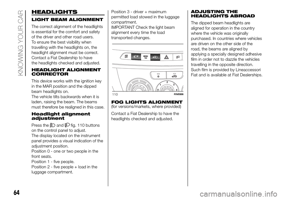
Press the
andfig. 110 buttons
on the control panel to adjust.
The display located on the instrument
panel provides a visual indication of the
adjustment position.
Position 0 - one or two people in the
front seats.
Position 1 - five people.
Position 2 - five people + load in the
luggage compartment.Position 3 - driver + maximum
permitted load stowed in the luggage
compartment.
IMPORTANT Check the light beam
alignment every time the load
transported changes.
FOG LIGHTS ALIGNMENT
(for versions/markets, where provided)
Contact a Fiat Dealership to have the
headlights checked and adjusted.ADJUSTING THE
HEADLIGHTS ABROAD
The dipped beam headlights are
aligned for operation in the country
where the vehicle was originally
purchased. In countries where vehicles
are driven on the other side of the
road, the beams are aligned by
applying a specially designed adhesive
film in order not to dazzle the vehicles
travelling in the opposite direction.
Such film is provided by Lineaccessori
Fiat and is available at Fiat Dealerships.
110F0V0506
64
KNOWING YOUR CAR
Page 75 of 298
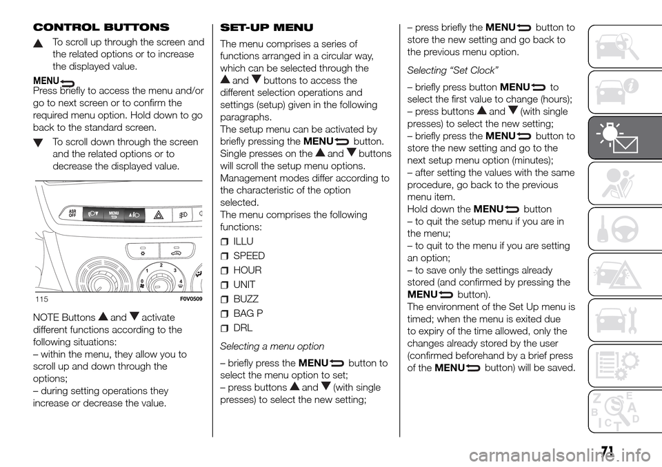
CONTROL BUTTONS
To scroll up through the screen and
the related options or to increase
the displayed value.
MENUPress briefly to access the menu and/or
go to next screen or to confirm the
required menu option. Hold down to go
back to the standard screen.
To scroll down through the screen
and the related options or to
decrease the displayed value.
NOTE Buttons
andactivate
different functions according to the
following situations:
– within the menu, they allow you to
scroll up and down through the
options;
– during setting operations they
increase or decrease the value.SET-UP MENU
The menu comprises a series of
functions arranged in a circular way,
which can be selected through the
andbuttons to access the
different selection operations and
settings (setup) given in the following
paragraphs.
The setup menu can be activated by
briefly pressing theMENU
button.
Single presses on the
andbuttons
will scroll the setup menu options.
Management modes differ according to
the characteristic of the option
selected.
The menu comprises the following
functions:
ILLU
SPEED
HOUR
UNIT
BUZZ
BAG P
DRL
Selecting a menu option
– briefly press theMENU
button to
select the menu option to set;
– press buttons
and(with single
presses) to select the new setting;– press briefly theMENU
button to
store the new setting and go back to
the previous menu option.
Selecting “Set Clock”
– briefly press buttonMENU
to
select the first value to change (hours);
– press buttons
and(with single
presses) to select the new setting;
– briefly press theMENU
button to
store the new setting and go to the
next setup menu option (minutes);
– after setting the values with the same
procedure, go back to the previous
menu item.
Hold down theMENU
button
– to quit the setup menu if you are in
the menu;
– to quit to the menu if you are setting
an option;
– to save only the settings already
stored (and confirmed by pressing the
MENU
button).
The environment of the Set Up menu is
timed; when the menu is exited due
to expiry of the time allowed, only the
changes already stored by the user
(confirmed beforehand by a brief press
of theMENU
button) will be saved.
115F0V0509
71
Page 105 of 298
BRAKE ASSIST
(integrated ESP
emergency braking
assistance)
(for versions/markets, where provided)
This system (which cannot be
deactivated) recognises emergency
braking conditions according to the
speed of operation of the brake pedal
and provides an additional hydraulic
braking pressure to support that
provided by the driver. This allows
faster and more powerful operation of
the braking system.
Brake Assist is deactivated on the
versions equipped with ESP, in the
event of ESC system failure (indicated
by the
warning light coming on
together with a message in the
multifunction display, where provided).
WARNING
53)When the ABS cuts in and you feel the
brake pedal pulsating, do not remove
your foot, but keep the pedal pushed
down; in doing so you, will stop in the
shortest distance possible under the road
conditions at the time.
54)If the ABS system intervenes, this
indicates that the traction of the tyres on
the road is nearing its limit. You must slow
down to a speed compatible with the
available traction.55)The ABS gets the most from the
available grip, but it cannot improve it; you
should therefore take every care when
driving on slippery surfaces and not take
unnecessary risks.
56)If only the
instrument panel
warning light comes on (with a message in
the multifunction display on some
versions), stop the vehicle immediately and
contact the nearest Fiat Dealership. Any
loss of fluid will affect the brake system
functionality, both conventional and
ant-lock wheels.
ESC (Electronic
Stability Control)
SYSTEM
(for versions/markets, where provided)
IN BRIEF
This is an electronic system that
controls vehicle stability in the event
of tyre grip loss, helping to maintain
directional control.
The ESC system is therefore
particularly useful when grip
conditions of road surfaces change.
The MSR system (adjustment of
the engine braking torque during gear
changes) and the HBA system
(automatic increase in the braking
pressure during emergency braking)
are present with ESC, ASR and
Hill Holder systems (for
versions/markets where provided).
SYSTEM INTERVENTION
This is signalled by the flashing of the
warning light in the instrument panel,
to inform the driver that the vehicle is
in critical stability and grip conditions.
101
Page 130 of 298
If the vehicle is parked on a steep
slope, it is advisable to block the
wheels with a wedge or stone.
To prevent draining the battery, do not
leave the ignition key turned to MAR.
Always remove the key when you leave
the vehicle.
Never leave children unattended in the
vehicle. Always remove the ignition
key when leaving the vehicle, and take
it with you.
WARNING
96)The vehicle should be secured after
several clicks of the lever. If it is not,
contact a Fiat Dealership to have it
adjusted.
USING THE
GEARBOX
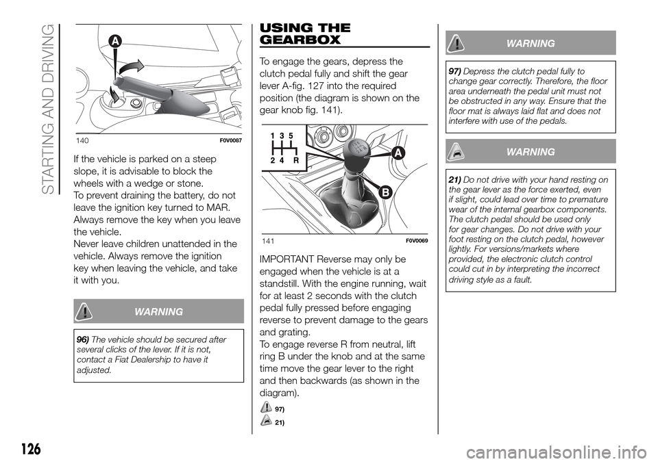
To engage the gears, depress the
clutch pedal fully and shift the gear
lever A-fig. 127 into the required
position (the diagram is shown on the
gear knob fig. 141).
IMPORTANT Reverse may only be
engaged when the vehicle is at a
standstill. With the engine running, wait
for at least 2 seconds with the clutch
pedal fully pressed before engaging
reverse to prevent damage to the gears
and grating.
To engage reverse R from neutral, lift
ring B under the knob and at the same
time move the gear lever to the right
and then backwards (as shown in the
diagram).
97)
21)
WARNING
97)Depress the clutch pedal fully to
change gear correctly. Therefore, the floor
area underneath the pedal unit must not
be obstructed in any way. Ensure that the
floor mat is always laid flat and does not
interfere with use of the pedals.
WARNING
21)Do not drive with your hand resting on
the gear lever as the force exerted, even
if slight, could lead over time to premature
wear of the internal gearbox components.
The clutch pedal should be used only
for gear changes. Do not drive with your
foot resting on the clutch pedal, however
lightly. For versions/markets where
provided, the electronic clutch control
could cut in by interpreting the incorrect
driving style as a fault.
140F0V0087
141F0V0069
126
STARTING AND DRIVING
Page 135 of 298
The TPMS does not replace the
normal tyre maintenance service and
does not indicate any fault in a tyre.
Therefore, the TPMS should not be
used as pressure switch while adjusting
the tyre inflation pressure.
Driving with insufficient tyre pressure
causes their overheating and can
result in tyre failure. The low inflation
pressure reduces fuel efficiency and
tyre tread life and may also affect
handling and braking performance of
the vehicle.
The TPMS does not replace the
correct tyre maintenance. It is up to the
driver to maintain the correct tyre
pressure level measuring it with
a suitable pressure switch. This is
necessary even if the decrease in the
inflation pressure value does not cause
the tyre pressure control warning light
to switch on.
The TPMS warns the driver of any
condition of insufficient tyre pressure
If this drops below the insufficient
pressure limit for any reason including
low temperature and normal pressure
loss of the tyre.
The seasonal temperature changes
affect tyre pressure.The TPMS uses wireless devices with
electronic sensors mounted on the
wheel rims to constantly monitor the
value of tyre pressure. The sensors
mounted on each wheel as part of the
valve stem transmit various information
of the tyres to the receiver module, in
order to calculate the pressure.
IMPORTANT Monitoring and
maintaining the correct pressure in all
four tyres are particularly important.
Tyre pressure monitoring system
low pressure warning
The system warns the driver if one or
more tyres are flat by switching on
the warning light
on the instrument
panel (together with a warning message
and an acoustic signal).The TPMS continues to advise the
driver of the low tyre pressure condition
until this is corrected; the warning
continues until the pressure
corresponds or exceeds the pressure
prescribed for the cold tyres. When the
tyre low pressure control warning
light
switches on constantly, the
inflation pressure must be adjusted until
it reaches the pressure prescribed for
cold tyres. After the automatic update
of the system, the tyre pressure control
warning light switches off. You may
need to drive the vehicle for about 20
minutes at a speed higher than 20
km/h to allow the TPMS to receive this
information.
IMPORTANT In the case of deflation of
more than one tyre sequentially, without
switching off and on the engine, from
the second tyre involved the acoustic
signal is not activated, only the
dedicated signal is shown on the
display.
To prevent the signal from being stored
in the event of pressure loss of a
subsequent tyre (with deactivation of
the acoustic signal), the ignition key
must be turned to MAR and then to
STOP, each time pressure is restored.
131
Page 141 of 298
OPERATION WITH
TRAILER
Parking sensor operation is
automatically deactivated when the
electric cable plug of the trailer is
inserted into the vehicle tow hook
socket. The sensors are automatically
reactivated when the trailer's cable plug
is removed.
IMPORTANT
If you wish to leave the tow hook fitted
without towing a trailer, it is advisable to
contact a Fiat Dealership for the
relevant system update operations
because the tow hook could be
detected as an obstacle by the central
sensors.
GENERAL WARNINGS
115)
When parking, take the utmost care
over obstacles that may be above or
under the sensor.
Sometimes, objects located very
near the rear of the vehicle are not
detected and could therefore damage
the vehicle or be damaged themselves.
The following conditions may influence
the performance of the parking
assistance system:
Reduced sensor sensitivity and a
reduction in the parking assistance
system performance could be due to
the presence on the surface of the
sensor of: ice, snow, mud, thick paint.
The sensor may detect a non-
existent obstacle (echo noise) due to
mechanical noises, for example when
washing the vehicle, in case of rain,
strong wind, hail.
The signals sent out by the sensors
can be altered by dirt, snow or ice
deposited on the sensors or by
ultrasound systems (e.g. truck
pneumatic brakes or pneumatic drills)
near the vehicle.
The performance of the parking
assistance system may also be affected
by the position of the sensors. For
example by a change in the ride setting
(caused by the wear of the shock
absorbers, suspension), changing the
tyres, overloading the vehicle and
carrying out specific tuning operations
that require the vehicle to be lowered.
Detection of obstacles in the upper
part of the vehicle (particularly in the
case of vans or chassis cabs) may not
be guaranteed because the system
detects obstacles that could strike the
lower part of the vehicle.
The parking sensors work properly
with the swing doors closed.
If they are open, they can cause the
system to send false signals: always
close the rear doors.
Do not apply stickers to the sensors.
WARNING
114)The sensors must be clean of mud,
dirt, snow and ice in order for the system
to work. Be careful not to scratch or
damage the sensors while cleaning them.
Avoid using dry, rough or hard cloths.
The sensors must be washed using clean
water, with the addition of car shampoo
if necessary. When using special washing
equipment such as high pressure jets or
steam cleaning, clean the sensors very
quickly keeping the jet more than 10 cm
away.
115)Parking manoeuvres, however, are
always the driver’s responsibility. While
carrying out these manoeuvres, always
make sure that no people (especially
children) or animals are in the area
concerned. The parking sensor is designed
to assist drivers, who must still never
allow their attention to lapse during
potentially dangerous manoeuvres even if
performed at low speed.
137