FIAT DUCATO 2006 Owner handbook (in English)
Manufacturer: FIAT, Model Year: 2006, Model line: DUCATO, Model: FIAT DUCATO 2006Pages: 238, PDF Size: 3.29 MB
Page 151 of 238
150
WARNING
LIGHTS AND
MESSAGES
VEHICLE
MAINTENANCE
TECHNICAL
SPECIFICATIONS
IINDEX
DASHBOARD
AND CONTROLS
SAFETY
DEVICES
CORRECT USE
OF THE
VEHICLE
IN AN
EMERGENCY
WHEN NEEDING TO
CHANGE A BULB
GENERAL INSTRUCTIONS
❒When a light is not working, check
that the corresponding fuse is intact
before changing a bulb. For the loca-
tion of fuses, refer to the paragraph “If
a fuse blows” in this section;
❒Before changing a bulb check the con-
tacts for oxidation;
❒Burnt bulbs must be replaced by oth-
ers of the same type and power;
❒Always check the height of the head-
light beam after changing a bulb.
IMPORTANT The headlight inner surface
may be lightly misted over: this is not a
fault but a natural fact due to low tem-
perature and the level of air humidity. It
will disappear as soon the headlights are
turned on. The presence of drops inside
the headlights means water infiltration,
therefore contact Fiat Dealership.
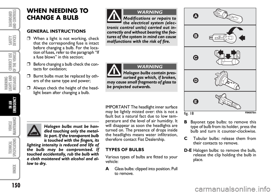
TYPES OF BULBS
Various types of bulbs are fitted to your
vehicle:
AGlass bulbs: clipped into position. Pull
to remove.BBayonet type bulbs: to remove this
type of bulb from its holder, press the
bulb and turn it counter-clockwise.
CTubular bulbs: release them from
their contacts to remove.
D-EHalogen bulbs: to remove the bulb,
release the clip holding the bulb in
place. Halogen bulbs must be han-
dled touching only the metal-
lic part. If the transparent bulb
is touched with the fingers, its
lighting intensity is reduced and life of
the bulb may be compromised. If
touched accidentally, rub the bulb with
a cloth moistened with alcohol and al-
low to dry.
Modifications or repairs to
the electrical system (elec-
tronic control units) carried out in-
correctly and without bearing the fea-
tures of the system in mind can cause
malfunctions with the risk of fire.
WARNING
Halogen bulbs contain pres-
surised gas which, if broken,
may cause small fragments of glass to
be projected outwards.
WARNING
fig. 18F0N0078m
Page 152 of 238
151
WARNING
LIGHTS AND
MESSAGES
VEHICLE
MAINTENANCE
TECHNICAL
SPECIFICATIONS
INDEX
DASHBOARD
AND CONTROLS
SAFETY
DEVICES
CORRECT USE
OF THE
VEHICLE
IN AN
EMERGENCY
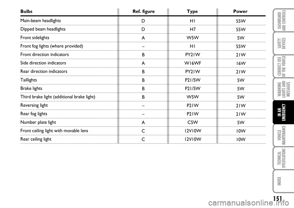
Bulbs Ref. figure Type Power
Main-beam headlights
Dipped beam headlights
Front sidelights
Front fog lights (where provided)
Front direction indicators
Side direction indicators
Rear direction indicators
Taillights
Brake lights
Third brake light (additional brake light)
Reversing light
Rear fog lights
Number plate light
Front ceiling light with movable lens
Rear ceiling lightH1
H7
W5W
H1
PY21W
W16WF
PY21W
P21/5W
P21/5W
W5W
P21W
P21W
C5W
12V10W
12V10W D
D
A
–
B
A
B
B
B
B
–
–
A
C
C55W
55W
5W
55W
21W
16W
21W
5W
5W
5W
21W
21W
5W
10W
10W
Page 153 of 238
152
WARNING
LIGHTS AND
MESSAGES
VEHICLE
MAINTENANCE
TECHNICAL
SPECIFICATIONS
IINDEX
DASHBOARD
AND CONTROLS
SAFETY
DEVICES
CORRECT USE
OF THE
VEHICLE
IN AN
EMERGENCY
IF AN EXTERIOR LIGHT
BURNS OUT
For the type of bulb and power rating, see
“When needing to change a bulb”.
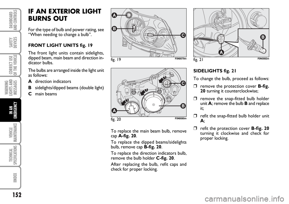
FRONT LIGHT UNITS fig. 19
The front light units contain sidelights,
dipped beam, main beam and direction in-
dicator bulbs.
The bulbs are arranged inside the light unit
as follows:
Adirection indicators
Bsidelights/dipped beams (double light)
Cmain beams
To replace the main beam bulb, remove
cap A-fig. 20.
To replace the dipped beams/sidelights
bulb, remove cap B-fig. 20.
To replace the direction indicators bulb,
remove the bulb holder C-fig. 20.
After replacing the bulb, refit caps and
check for proper locking.SIDELIGHTS fig. 21
To change the bulb, proceed as follows:
❒remove the protection cover B-fig.
20turning it counterclockwise;
❒remove the snap-fitted bulb holder
unit A; remove the bulb Band replace
it;
❒refit the snap-fitted bulb holder unit
A;
❒refit the protection cover B-fig. 20
turning it clockwise and check for
proper locking.
fig. 19F0N0079mfig. 21F0N0082m
fig. 20F0N0080m
Page 154 of 238
153
WARNING
LIGHTS AND
MESSAGES
VEHICLE
MAINTENANCE
TECHNICAL
SPECIFICATIONS
INDEX
DASHBOARD
AND CONTROLS
SAFETY
DEVICES
CORRECT USE
OF THE
VEHICLE
IN AN
EMERGENCY
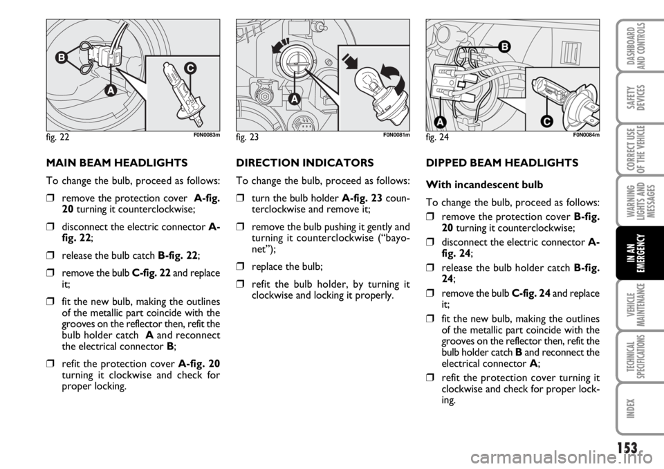
MAIN BEAM HEADLIGHTS
To change the bulb, proceed as follows:
❒remove the protection cover A-fig.
20 turning it counterclockwise;
❒disconnect the electric connector A-
fig. 22;
❒release the bulb catch B-fig. 22;
❒remove the bulb C-fig. 22 and replace
it;
❒fit the new bulb, making the outlines
of the metallic part coincide with the
grooves on the reflector then, refit the
bulb holder catch Aand reconnect
the electrical connector B;
❒refit the protection cover A-fig. 20
turning it clockwise and check for
proper locking.DIRECTION INDICATORS
To change the bulb, proceed as follows:
❒turn the bulb holder A-fig. 23coun-
terclockwise and remove it;
❒remove the bulb pushing it gently and
turning it counterclockwise (“bayo-
net”);
❒replace the bulb;
❒refit the bulb holder, by turning it
clockwise and locking it properly.DIPPED BEAM HEADLIGHTS
With incandescent bulb
To change the bulb, proceed as follows:
❒remove the protection cover B-fig.
20turning it counterclockwise;
❒disconnect the electric connector A-
fig. 24;
❒release the bulb holder catch B-fig.
24;
❒remove the bulb C-fig. 24and replace
it;
❒fit the new bulb, making the outlines
of the metallic part coincide with the
grooves on the reflector then, refit the
bulb holder catch Band reconnect the
electrical connector A;
❒refit the protection cover turning it
clockwise and check for proper lock-
ing.
fig. 22F0N0083mfig. 23F0N0081mfig. 24F0N0084m
Page 155 of 238
154
WARNING
LIGHTS AND
MESSAGES
VEHICLE
MAINTENANCE
TECHNICAL
SPECIFICATIONS
IINDEX
DASHBOARD
AND CONTROLS
SAFETY
DEVICES
CORRECT USE
OF THE
VEHICLE
IN AN
EMERGENCY
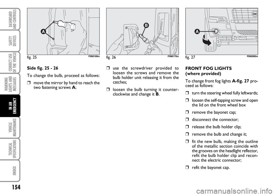
Side fig. 25 - 26
To change the bulb, proceed as follows:
❒move the mirror by hand to reach the
two fastening screws A;FRONT FOG LIGHTS
(where provided)
To change front fog lights A-fig. 27pro-
ceed as follows:
❒turn the steering wheel fully leftwards;
❒loosen the self-tapping screw and open
the lid on the front wheel box
❒remove the bayonet cap;
❒disconnect the connector;
❒release the bulb holder clip;
❒remove the bulb and change it;
❒fit the new bulb, making the outline
of the metallic section coincide with
the grooves on the headlight reflector,
refit the bulb holder clip and recon-
nect the electric connector;
❒refit the bayonet cap.
fig. 25F0N0169mfig. 27F0N0085mfig. 26F0N0170m
❒use the screwdriver provided to
loosen the screws and remove the
bulb holder unit releasing it from the
catches;
❒loosen the bulb turning it counter-
clockwise and change it B.
Page 156 of 238
155
WARNING
LIGHTS AND
MESSAGES
VEHICLE
MAINTENANCE
TECHNICAL
SPECIFICATIONS
INDEX
DASHBOARD
AND CONTROLS
SAFETY
DEVICES
CORRECT USE
OF THE
VEHICLE
IN AN
EMERGENCY
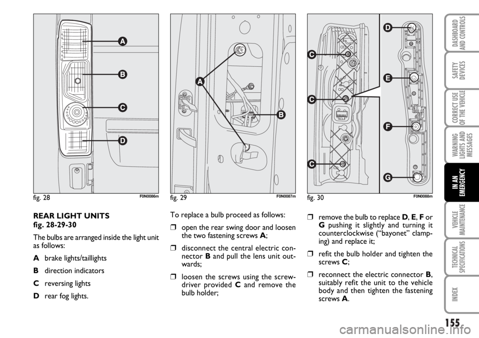
REAR LIGHT UNITS
fig. 28-29-30
The bulbs are arranged inside the light unit
as follows:
Abrake lights/taillights
Bdirection indicators
Creversing lights
Drear fog lights.
fig. 28F0N0086m
To replace a bulb proceed as follows:
❒open the rear swing door and loosen
the two fastening screws A;
❒disconnect the central electric con-
nector B and pull the lens unit out-
wards;
❒loosen the screws using the screw-
driver provided Cand remove the
bulb holder;
❒remove the bulb to replace D, E, For
Gpushing it slightly and turning it
counterclockwise (“bayonet” clamp-
ing) and replace it;
❒refit the bulb holder and tighten the
screws C;
❒reconnect the electric connector B,
suitably refit the unit to the vehicle
body and then tighten the fastening
screws A.
fig. 30F0N0088mfig. 29F0N0087m
Page 157 of 238
156
WARNING
LIGHTS AND
MESSAGES
VEHICLE
MAINTENANCE
TECHNICAL
SPECIFICATIONS
IINDEX
DASHBOARD
AND CONTROLS
SAFETY
DEVICES
CORRECT USE
OF THE
VEHICLE
IN AN
EMERGENCY
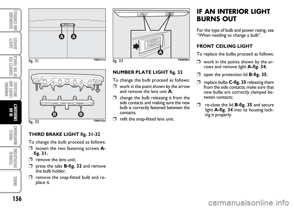
THIRD BRAKE LIGHT fig. 31-32
To change the bulb proceed as follows:
❒loosen the two fastening screws A-
fig. 31;
❒remove the lens unit;
❒press the tabs B-fig. 32and remove
the bulb holder;
❒remove the snap-fitted bulb and re-
place it.NUMBER PLATE LIGHT fig. 33
To change the bulb proceed as follows:
❒work in the point shown by the arrow
and remove the lens unit A;
❒change the bulb releasing it from the
side contacts and making sure the new
bulb is correctly fastened between the
contacts;
❒refit the snap-fitted lens unit.
IF AN INTERIOR LIGHT
BURNS OUT
For the type of bulb and power rating, see
“When needing to change a bulb”.
FRONT CEILING LIGHT
To replace the bulbs proceed as follows:
❒work in the points shown by the ar-
rows and remove light A-fig. 34;
❒open the protection lid B-fig. 35;
❒replace bulbs C-fig. 35releasing them
from the side contacts; make sure that
new bulbs are correctly clamped be-
tween contacts;
❒re-close the lid B-fig. 35and secure
light A-fig. 34into its housing lock-
ing it properly.
fig. 32F0N0142m
fig. 33F0N0089mfig. 31F0N0141m
Page 158 of 238
157
WARNING
LIGHTS AND
MESSAGES
VEHICLE
MAINTENANCE
TECHNICAL
SPECIFICATIONS
INDEX
DASHBOARD
AND CONTROLS
SAFETY
DEVICES
CORRECT USE
OF THE
VEHICLE
IN AN
EMERGENCY
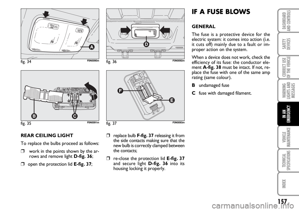
REAR CEILING LIGHT
To replace the bulbs proceed as follows:
❒work in the points shown by the ar-
rows and remove light D-fig. 36;
❒open the protection lid E-fig. 37;
❒replace bulb F-fig. 37releasing it from
the side contacts making sure that the
new bulb is correctly clamped between
the contacts;
❒re-close the protection lid E-fig. 37
and secure light D-fig. 36into its
housing locking it properly.
fig. 34F0N0090m
fig. 35F0N0091m
fig. 36F0N0092m
fig. 37F0N0093m
IF A FUSE BLOWS
GENERAL
The fuse is a protective device for the
electric system: it comes into action (i.e.
it cuts off) mainly due to a fault or im-
proper action on the system.
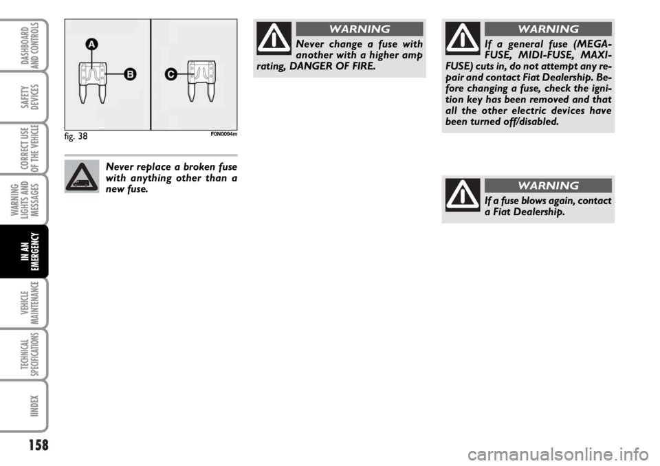
When a device does not work, check the
efficiency of its fuse: the conductor ele-
ment A-fig. 38must be intact. If not, re-
place the fuse with one of the same amp
rating (same colour).
Bundamaged fuse
Cfuse with damaged filament.
Page 159 of 238
158
WARNING
LIGHTS AND
MESSAGES
VEHICLE
MAINTENANCE
TECHNICAL
SPECIFICATIONS
IINDEX
DASHBOARD
AND CONTROLS
SAFETY
DEVICES
CORRECT USE
OF THE
VEHICLE
IN AN
EMERGENCY
fig. 38F0N0094m
Never change a fuse with
another with a higher amp
rating, DANGER OF FIRE.
WARNING
Never replace a broken fuse
with anything other than a
new fuse.
If a general fuse (MEGA-
FUSE, MIDI-FUSE, MAXI-
FUSE) cuts in, do not attempt any re-
pair and contact Fiat Dealership. Be-
fore changing a fuse, check the igni-
tion key has been removed and that
all the other electric devices have
been turned off/disabled.
WARNING
If a fuse blows again, contact
a Fiat Dealership.
WARNING
Page 160 of 238
159
WARNING
LIGHTS AND
MESSAGES
VEHICLE
MAINTENANCE
TECHNICAL
SPECIFICATIONS
INDEX
DASHBOARD
AND CONTROLS
SAFETY
DEVICES
CORRECT USE
OF THE
VEHICLE
IN AN
EMERGENCY
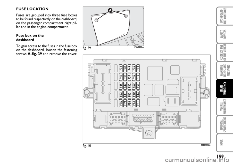
FUSE LOCATION
Fuses are grouped into three fuse boxes
to be found respectively on the dashboard,
on the passenger compartment right pil-
lar and in the engine compartment.
Fuse box on the
dashboard
To gain access to the fuses in the fuse box
on the dashboard, loosen the fastening
screws A-fig. 39and remove the cover.
fig. 40F0N0096m
fig. 39F0N0095m