ECU FIAT FIORINO 2019 Owner handbook (in English)
[x] Cancel search | Manufacturer: FIAT, Model Year: 2019, Model line: FIORINO, Model: FIAT FIORINO 2019Pages: 220, PDF Size: 6.22 MB
Page 102 of 220
16)There must therefore always be
enough petrol in the tank to protect the
petrol pump and to guarantee temporary
switching from methane to petrol
operation, if high performance is required.
17)If the engine fails to start with a gear
engaged, the potentially dangerous
situation due to the fact that the gearbox is
automatically placed in neutral will be
signalled by a buzzer.
18)Never, under any circumstances, jump
start the engine by pushing, towing or
coasting downhill. This could cause fuel to
flow into the catalytic converter and
damage it beyond repair.
19)A quick burst on the accelerator before
stopping the engine serves no practical
purpose; it wastes fuel and is especially
damaging to turbocharged engines.HANDBRAKE
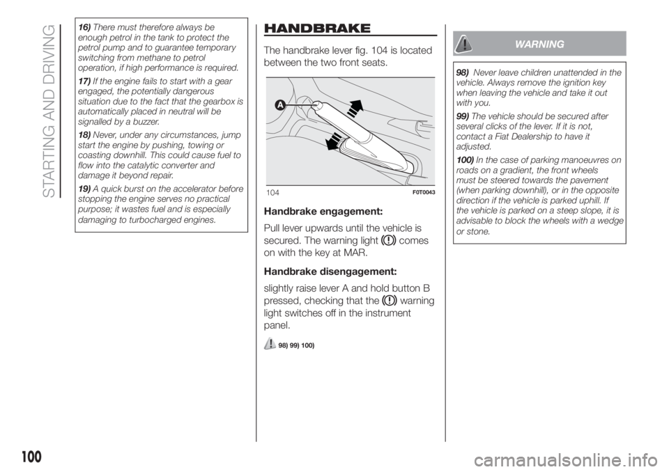
The handbrake lever fig. 104 is located
between the two front seats.
Handbrake engagement:
Pull lever upwards until the vehicle is
secured. The warning light
comes
on with the key at MAR.
Handbrake disengagement:
slightly raise lever A and hold button B
pressed, checking that the
warning
light switches off in the instrument
panel.
98) 99) 100)
WARNING
98)Never leave children unattended in the
vehicle. Always remove the ignition key
when leaving the vehicle and take it out
with you.
99)The vehicle should be secured after
several clicks of the lever. If it is not,
contact a Fiat Dealership to have it
adjusted.
100)In the case of parking manoeuvres on
roads on a gradient, the front wheels
must be steered towards the pavement
(when parking downhill), or in the opposite
direction if the vehicle is parked uphill. If
the vehicle is parked on a steep slope, it is
advisable to block the wheels with a wedge
or stone.
104F0T0043
100
STARTING AND DRIVING
Page 122 of 220
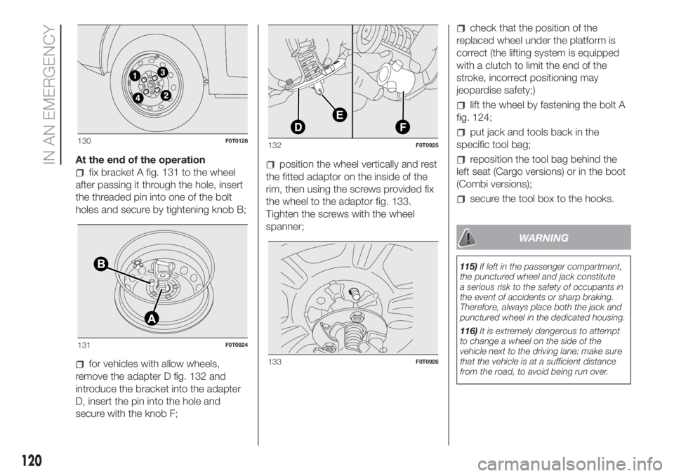
At the end of the operation
fix bracket A fig. 131 to the wheel
after passing it through the hole, insert
the threaded pin into one of the bolt
holes and secure by tightening knob B;
for vehicles with allow wheels,
remove the adapter D fig. 132 and
introduce the bracket into the adapter
D, insert the pin into the hole and
secure with the knob F;
position the wheel vertically and rest
the fitted adaptor on the inside of the
rim, then using the screws provided fix
the wheel to the adaptor fig. 133.
Tighten the screws with the wheel
spanner;
check that the position of the
replaced wheel under the platform is
correct (the lifting system is equipped
with a clutch to limit the end of the
stroke, incorrect positioning may
jeopardise safety;)
lift the wheel by fastening the bolt A
fig. 124;
put jack and tools back in the
specific tool bag;
reposition the tool bag behind the
left seat (Cargo versions) or in the boot
(Combi versions);
secure the tool box to the hooks.
WARNING
115)If left in the passenger compartment,
the punctured wheel and jack constitute
a serious risk to the safety of occupants in
the event of accidents or sharp braking.
Therefore, always place both the jack and
punctured wheel in the dedicated housing.
116)It is extremely dangerous to attempt
to change a wheel on the side of the
vehicle next to the driving lane: make sure
that the vehicle is at a sufficient distance
from the road, to avoid being run over.
130F0T0128
131F0T0924
132F0T0925
133F0T0926
120
IN AN EMERGENCY
Page 123 of 220
117)The space-saver wheel (for
versions/markets, where provided) is
specific to your vehicle, do not use it on
other models, or use the space-saver
wheel of other models on your vehicle. The
space-saver wheel must only be used in
the event of an emergency. Never use it for
more than strictly necessary and never
exceed 80 km/h. "Warning! For temporary
use only! 80km/h max! Replace with
standard wheel as soon as possible. Never
remove or cover the sticker on the
space-saver wheel. Never apply a wheel
cap on a space-saver wheel. The driving
characteristics of the vehicle will be
modified with the space-saver wheel fitted.
Avoid violent acceleration and braking,
abrupt steering and fast cornering.
118)Use your hazard lights, warning
triangle, etc to show that your vehicle is
stationary. Passengers should get out
of the vehicle, particularly if it is heavily
loaded, and wait for the wheel to be
changed away from the traffic. If you are on
a slope or uneven surface, place wedges
or other suitable objects under the wheels
to secure the vehicle. Have the wheel
repaired and refitted as soon as possible.
Do not apply grease to the bolt threads
before fitting: they could come unscrewed.119)The jack is a tool developed and
designed only for changing a wheel, if a
tyre gets punctured or damaged, on the
vehicle with which it is supplied or on other
vehicles of the same model. Any other
use, e.g. to jack up other vehicle models or
different things, is strictly prohibited. Never
use it to carry out maintenance or repairs
under the vehicle or to change summer/
winter wheels and vice versa: we advise
you to contact a Fiat Dealership. Never go
under the raised vehicle: use it only in
the positions indicated. Do not use the jack
for loads higher than the one shown on
its label. Never start the engine with vehicle
raised. If the vehicle is raised more than
necessary, everything can become more
unstable, with the risk of the vehicle
dropping violently. Thus, lift the vehicle only
as needed in order to access the spare
wheel.
120)Incorrect hub cap assembly may
cause it to come off when the vehicle is
moving. Never tamper with the inflation
valve. Never introduce tools of any kind
between rim and tyre. Check tyre and
space-saver wheel pressures regularly,
referring to the values shown in the
"Technical data" chapter.
WARNING
28)When turning the jack handle make
sure that it can turn freely without scraping
your hand against the ground. The moving
components of the jack ("worm screw"
and joints) can also cause injuries: do not
touch them. If you come into contact
with lubricating grease, clean yourself
thoroughly.
29)Contact a Fiat Dealership as soon as
possible to have the correct tightening
of the fixing bolts checked.
121
Page 126 of 220
WARNING
121)The information required by the
applicable regulation is indicated on the
Fix&Go kit package label. Carefully read
the label on the cartridge before use, avoid
improper use. The kit should be used by
adults and cannot be used by children.
122)IMPORTANT: Do not exceed 80 km/h.
Avoid sudden acceleration or braking.
The kit provides a temporary repair,
therefore the tyre must be examined and
repaired by a specialist as soon as
possible. Before using the kit, ensure that
the tyre is not excessively damaged and
that the rim is in good condition, otherwise
do not use it and call roadside assistance.
Do not remove foreign bodies from the
tyre. Do not let the compressor turned on
for more than 20 consecutive minutes -
overheating hazard.
WARNING
30)The sealant fluid is effective with
external temperatures between -40°C and
+55°C. The sealant has an expiry date. It
is possible to repair tyres which have been
damaged on tread up to a diameter of 6
mm. Show the cartridge and the label
to the personnel who will handle the tyre
treated with the tyre repair kit
CHANGING A BULB
GENERAL
INSTRUCTIONS
123) 124) 125) 126) 127)
Before replacing a bulb check the
contacts for oxidation;
burnt bulbs must be replaced by
others of the same type and power;
always check the headlight beam
direction after changing a bulb;
when a light is not working, check
that the corresponding fuse is intact
before replacing a bulb. For the location
of fuses, refer to the paragraph
"Replacing fuses" in this chapter.
IMPORTANT A slight misting may
appear on the internal surface of the
headlight: this does not indicate a fault
and is caused by low temperature
and the degree of humidity in the air.
Misting will rapidly disappear when the
headlights are switched on. The
presence of drops inside the headlights
indicates infiltration of water. Contact
a Fiat Dealership.
WARNING
123)Modifications or repairs to the electric
system that are not carried out properly
or do not take the system technical
specifications into account can cause
malfunctions leading to the risk of fire.
124)Halogen bulbs contain pressurised
gas, in the case of breakage they may
burst causing glass fragments to be
projected outwards.
125)Halogen bulbs must be handled
holding the metal part only. Touching the
transparent part of the bulb with your
fingers may reduce the intensity of the
emitted light and even reduce the lifespan
of the bulb. In the event of accidental
contact, wipe the bulb with a cloth
moistened with alcohol and let the bulb dry.
126)Where possible, it is advisable to
have bulbs changed at a Fiat Dealership.
The correct operation and direction of
the external lights are absolutely essential
for the safety of the car and of compliance
with the law.
127)Replace the bulbs with the engine
stopped and in a position in which it is not
danger for oncoming traffic and where
you perform the replacement safely (see
the “When parked” paragraph). Also ensure
that the engine is cold, to prevent the risk
of burns.
124
IN AN EMERGENCY
Page 132 of 220
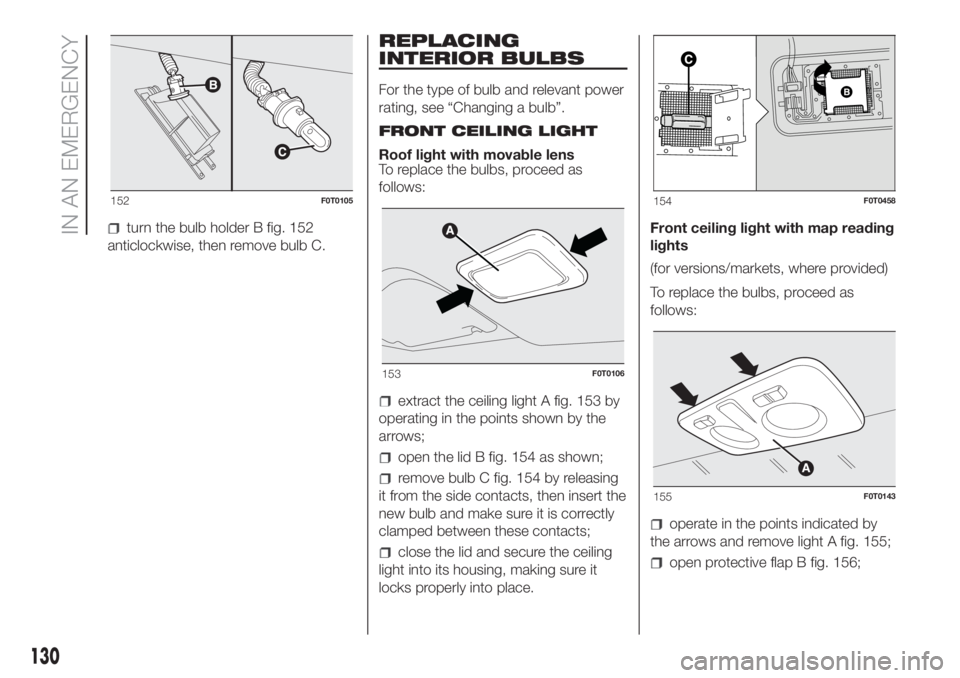
turn the bulb holder B fig. 152
anticlockwise, then remove bulb C.
REPLACING
INTERIOR BULBS
For the type of bulb and relevant power
rating, see “Changing a bulb”.
FRONT CEILING LIGHT
Roof light with movable lens
To replace the bulbs, proceed as
follows:
extract the ceiling light A fig. 153 by
operating in the points shown by the
arrows;
open the lid B fig. 154 as shown;
remove bulb C fig. 154 by releasing
it from the side contacts, then insert the
new bulb and make sure it is correctly
clamped between these contacts;
close the lid and secure the ceiling
light into its housing, making sure it
locks properly into place.Front ceiling light with map reading
lights
(for versions/markets, where provided)
To replace the bulbs, proceed as
follows:
operate in the points indicated by
the arrows and remove light A fig. 155;
open protective flap B fig. 156;
152F0T0105
153F0T0106
154F0T0458
155F0T0143
130
IN AN EMERGENCY
Page 133 of 220
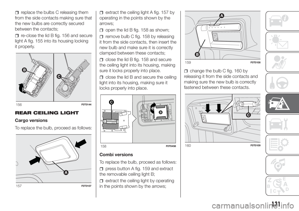
replace the bulbs C releasing them
from the side contacts making sure that
the new bulbs are correctly secured
between the contacts;
re-close the lid B fig. 156 and secure
light A fig. 155 into its housing locking
it properly.
REAR CEILING LIGHT
Cargo versions
To replace the bulb, proceed as follows:
extract the ceiling light A fig. 157 by
operating in the points shown by the
arrows;
open the lid B fig. 158 as shown;
remove bulb C fig. 158 by releasing
it from the side contacts, then insert the
new bulb and make sure it is correctly
clamped between these contacts;
close the lid B fig. 158 and secure
the ceiling light into its housing, making
sure it locks properly into place.
close the lid B and secure the ceiling
light into its housing, making sure it
locks properly into place.
Combi versions
To replace the bulb, proceed as follows:
press button A fig. 159 and extract
the removable ceiling light B;
extract the ceiling light by operating
in the points shown by the arrows;
change the bulb C fig. 160 by
releasing it from the side contacts and
making sure the new bulb is correctly
fastened between these contacts.
156F0T0144
157F0T0107
158F0T0458
A
U
T
O
159F0T0108
A
U
T
O
160F0T0109
131
Page 139 of 220
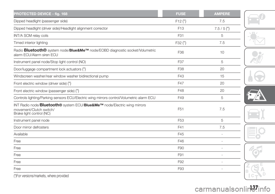
PROTECTED DEVICE - fig. 168 FUSE AMPERE
Dipped headlight (passenger side)
F12(*)7.5
Dipped headlight (driver side)/Headlight alignment corrector F13
7.5 / 5
(*)
INT/A SCM relay coilsF31 5
Timed interior lighting
F32
(*)7.5
Radio
Bluetooth®system node/Blue&Me™node/EOBD diagnostic socket/Volumetric
alarm ECU/Alarm siren ECUF36 10
Instrument panel node/Stop light control (NO) F37 5
Door/luggage compartment lock actuators
(*)F38 20
Windscreen washer/rear window washer bidirectional pump F43 15
Front electric window (driver side)
(*)F47 20
Front electric window (passenger side)
(*)F48 20
Controls lighting/Parking sensors ECU/Electric wing mirrors control/Volumetric alarm ECU F49 5
INT Radio node/
Bluetooth®system ECU/Blue&Me™node/Electric wing mirrors
movement/Clutch switch/
Brake light control (NC)F51 7.5
Instrument panel nodeF53 5
Door mirror defrostersF41 7.5
AvailableF45 -
FreeF46 -
FreeF90 -
FreeF91 -
FreeF92 -
FreeF93 -
(*)For versions/markets, where provided
137
Page 162 of 220
IMPORTANT The cables of the
electrical system must be correctly
reconnected to the battery, i.e. the
positive cable (+) to the positive
terminal and the negative cable (–) to
the negative terminal. The battery
terminals are marked with the positive
(+) and negative (–) symbols, and are
shown on the battery cover. The battery
terminals must also be corrosion-free
and firmly secured to the terminals. If a
"quick-type" battery charger is used
with the battery fitted on the car,
disconnect both battery leads before
connecting it. Do not use a "quick-type"
battery charger to provide the starting
voltage.
150) 151)
WARNING
150)Battery fluid is poisonous and
corrosive: avoid contact with your skin and
eyes. The battery should be charged in a
well ventilated place, away from naked
flames or possible sources of sparks:
danger of explosion and fire.151)Do not attempt to charge a frozen
battery: it must be thawed first, otherwise it
may explode. If freezing has occurred, the
battery should be checked by skilled
personnel to make sure that the internal
elements are not damaged and that the
body is not cracked, with the risk of leaking
poisonous and corrosive acid.
WINDSCREEN /
REAR WINDOW
WIPERS
(for versions/markets, where provided)
152)
Replacing the
windscreen wiper
blades
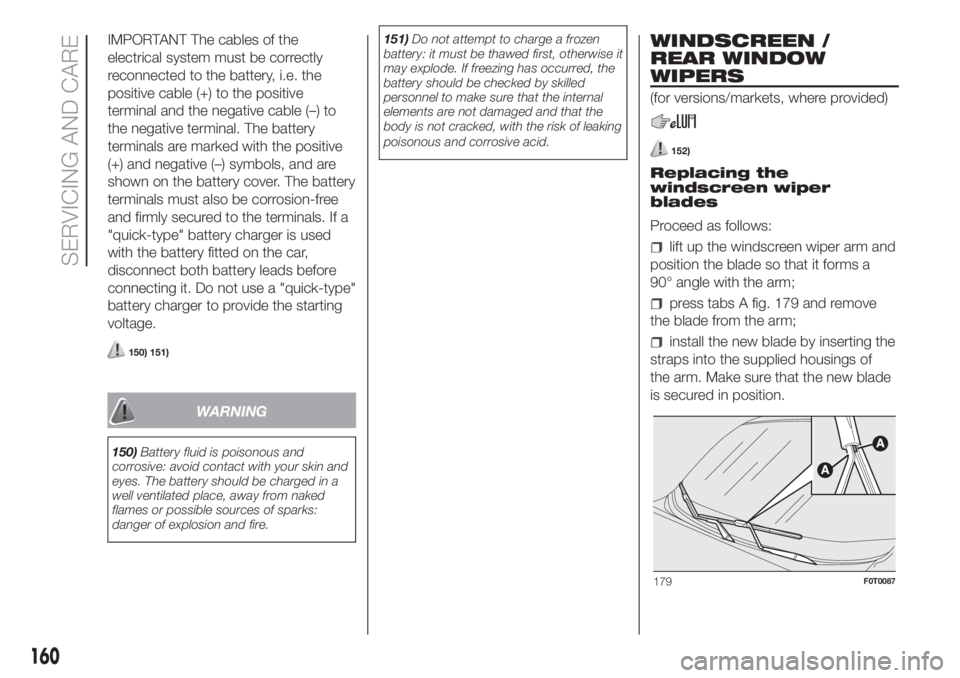
Proceed as follows:
lift up the windscreen wiper arm and
position the blade so that it forms a
90° angle with the arm;
press tabs A fig. 179 and remove
the blade from the arm;
install the new blade by inserting the
straps into the supplied housings of
the arm. Make sure that the new blade
is secured in position.
179F0T0087
160
SERVICING AND CARE
Page 216 of 220
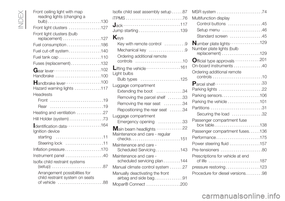
Front ceiling light with map
reading lights (changing a
bulb)............................130
Front light clusters.................127
Front light clusters (bulb
replacement)....................127
Fuel consumption..................186
Fuel cut-off system.................140
Fuel tank cap......................110
Fuses (replacement)................132
Gear lever.........................102
Handbrake........................100
Handbrake lever...................100
Hazard warning lights..............117
Headrests
Front ............................19
Rear............................19
Heating and ventilation..............27
Hill Holder (system)..................73
Identification data..................164
Ignition device
starting.........................11
Steering lock....................11
Inflation pressure...................170
Instrument panel....................40
Isofix child restraint systems
(setup)...........................87
Arrangement possibilities for
child restraint system on seats
of vehicle........................88Isofix child seat assembly setup......87
iTPMS..............................76
Jack..............................117
Jump starting......................139
Keys
Key with remote control...........9
Mechanical key...................9
Ordering additional remote
controls.........................10
Lifting the vehicle..................161
Light bulbs
Bulb types.....................125
Luggage compartment
Extending the boot..............34
Removing the parcel shelf........33
Removing the rear seat..........34
Repositioning the rear seat.......34
Luggage compartment
Emergency opening.............33
Main beam headlights..............22
Maintenance and care - regular
checks..........................151
Maintenance and care -
Scheduled Servicing.............143
Maintenance and care -
scheduled servicing plan.........144
Manual climate control system.......27
Manually deactivating the front
airbag and side bag...............91
Mopar® Connect..................200MSR system........................74
Multifunction display
Control buttons..................45
Setup menu.....................46
Standard screen.................45
Number plate lights................129
Number plate lights (bulb
replacement)....................129
Official type approvals.............201
On-board instruments...............40
Ordering additional remote
controls..........................10
Parcel shelf.........................33
Parking lights.......................22
Parking sensors....................106
Parking the vehicle.................101
Partitions...........................31
Securing the load................32
Passenger compartment fuse
box table........................138
Passenger compartment fuses......136
Performance.......................175
Power steering fluid................157
Pre-tensioners......................80
Prescriptions for vehicle at end
of life...........................187
pressure restoring..................123
Procedure for diesel versions.........98
INDEX