engine FIAT FREEMONT 2012 Owner handbook (in English)
[x] Cancel search | Manufacturer: FIAT, Model Year: 2012, Model line: FREEMONT, Model: FIAT FREEMONT 2012Pages: 332, PDF Size: 5.61 MB
Page 86 of 332
Turn the rear wiper off when driving
through an automatic car wash. Damage
to the rear wiper may result if the rear
wiper switch is left in the on position.
In cold weather, always turn off the rear wiper
switch and allow the rear wiper to return to the
park position before turning off the engine. If the
rear wiper switch is left on and the rear wiper
freezes to the window, damage to the rear wiper
motor may occur when the vehicle is restarted.
Always remove any buildup of snow that pre-
vents the rear wiper blade from returning to the
park position. If the rear wiper control is turned
off and the blade cannot return to the park
position, damage to the rear wiper motor may
occur.
REAR WINDOW DEFROSTER The rear window defroster button is located on
the climate control panel. Press this button to
turn on the rear window defroster and the heated
outside mirrors (for versions/markets, where pro-
vided). An indicator in the button will illuminate when
the rear window defroster is on. The rear window
defroster automatically turns off after approximately
10 minutes. NOTE:
To prevent excessive battery drain, use the
rear window defroster only when the engine is oper-ating.
Failure to follow these cautions can
cause damage to the heating elements:
Use care when washing the inside of
the rear window. Do not use abrasive window
cleaners on the interior surface of the window.
Use a soft cloth and a mild washing solution,
wiping parallel to the heating elements. Labels
can be peeled off after soaking with warm water.
Do not use scrapers, sharp instruments, or abra-
sive window cleaners on the interior surface of
the window.
Keep all objects a safe distance from the
window.
80
KNOWING YOUR
VEHICLE
SAFETY
STARTING AND
DRIVING
WARNING LIGHTSAND
MESSAGES
IN AN
EMERGENCY
SERVICING AND
CARETECHNICAL
SPECIFICATIONSCONTENTS
Page 98 of 332
Many accessories that can be plugged
in draw power from the vehicle's battery,
even when not in use (i.e., cellular
phones, etc .). Eventually, if plugged in long
enough, the vehicle's battery will discharge suffi-
ciently to degrade battery life and/or prevent the
engine from starting.
Accessories that draw higher power (i.e., cool-
ers, vacuum cleaners, lights, etc .) will degrade the
battery even more quickly. Only use these inter-
mittently and with greater caution.
After the use of high power draw accessories, or
long periods of the vehicle not being started (with
accessories still plugged in), the vehicle must be
driven a sufficient length of time to allow the
alternator to recharge the vehicle's battery.
Power outlets are designed for accessory plugs
only. Do not hang any type of accessory or acces-
sory bracket from the plug. CUPHOLDERS
There are two cupholders, located in the center floor
console, for the front passengers. (fig. 77)
For passengers in the second row there are two cup-
holders, located in the center armrest between the
two seats.
(fig. 77)
Floor Console Cupholders
92
KNOWING YOUR
VEHICLE
SAFETY
STARTING AND
DRIVING
WARNING LIGHTSAND
MESSAGES
IN AN
EMERGENCY
SERVICING AND
CARETECHNICAL
SPECIFICATIONSCONTENTS
Page 104 of 332
2. The transmission was in gear and the vehicle speedreturned to 0 km/h.
3. The transmission is in NEUTRAL or PARK.
4. The driver door is opened.
5. The doors were not previously unlocked.
6. The vehicle speed is 0 km/h.
To change the current setting, refer to “Uconnect
Touch™ Settings” in “Knowing Your Vehicle” for fur-
ther information.
NOTE: Use the Automatic Unlock Doors On Exit
feature in accordance with local laws.
Automatic Unlock Doors On Exit
Programming
The Automatic Unlock Doors On Exit feature can be
enabled or disabled as follows:
• For vehicles equipped with the Uconnect Touch™,
refer to “Uconnect Touch™ Settings” in “Knowing
Your Vehicle” for further information.
• For vehicles not equipped with the Uconnect Touch™, perform the following steps:
1. Enter the vehicle and close all doors.
2. Place the Key Fob in the ignition switch.
3. Within 15 seconds, cycle the ignition switch be- tween LOCK and ON/RUN and then back to LOCK
four times ending up in the LOCK position. How-
ever, do not start the engine. 4. Within 30 seconds, press the power door unlock
switch to unlock the doors.
5. A single chime will indicate the completion of the programming.
NOTE: If you do not hear the chime, it means that
the system did not enter the programming mode and
you will need to repeat the procedure.
6. Repeat these steps if you want to return this feature to its previous setting.
NOTE: Use the Automatic Unlock Doors On Exit
feature in accordance with local laws.
CHILD-PROTECTION DOOR LOCK SYSTEM
— REAR DOORS
To provide a safer environment for small children riding
in the rear seats, the rear doors are equipped with a
Child-Protection Door Lock system.
To Engage The Child-Protection Door Lock
System
1. Open the rear door.
2. Insert the tip of the emergency key (or alike) into the child lock control and rotate it to the LOCK
position. (fig. 83) (fig. 84)
3. Repeat Steps 1 and 2 for the opposite rear door.
NOTE: When the Child-Protection Door Lock sys-
tem is engaged, the door can be opened only by using
the outside door handle even though the inside door
lock is in the unlocked position.
98
KNOWING YOUR
VEHICLE
SAFETY
STARTING AND
DRIVING
WARNING LIGHTSAND
MESSAGES
IN AN
EMERGENCY
SERVICING AND
CARETECHNICAL
SPECIFICATIONSCONTENTS
Page 119 of 332
BRAKE SYSTEMYour vehicle is equipped with dual hydraulic
brake systems. If either of the two hydraulic
systems loses normal capability, the remaining system
will still function. However, there will be some loss of
overall braking effectiveness. This will be evident by
increased pedal travel during application and greater
pedal force required to slow or stop the vehicle. In
addition, if the malfunction is caused by a leak in the
hydraulic system, the “Brake System Warning Light”
will turn on as the brake fluid level drops in the master
cylinder.
In the event power assist is lost for any reason (i.e.,
repeated brake applications with the engine OFF) the
brakes will still function. However, the effort required
to brake the vehicle will be much greater than that
required with the power system operating.
WARNING!
Riding the brakes can lead to brake
failure and possibly an accident . Driving
with your foot resting or riding on the brake
pedal can result in abnormally high brake tem-
peratures, excessive lining wear, and possible
brake damage.You wouldn't have your full brak-
ing capacity in an emergency.
Driving a vehicle with the “Brake System Warn-
ing Light” on is dangerous. A significant decrease
in braking performance or vehicle stability dur-
ing braking may occur. It will take you longer to
stop the vehicle or will make your vehicle harder
to control.You could have an accident . Have the
vehicle checked immediately.
ANTI-LOCK BRAKE SYSTEM (ABS)
This system aids the driver in maintaining vehicle con-
trol under adverse braking conditions. The system
controls hydraulic brake pressure to prevent wheel
lock-up to help avoid skidding on slippery surfaces
during braking. Refer to “Anti-Lock Brake System
(ABS)” under “Knowing Your Vehicle/Electronic Brake
Control System” for further information.
113KNOWING
YOURVEHICLESAFETY
STARTING ANDDRIVING
WARNING LIGHTSAND
MESSAGES
IN AN
EMERGENCY
SERVICING AND
CARETECHNICAL
SPECIFICATIONSCONTENTS
Page 122 of 332
to operate normally if the Brake System Warning Light
is not on.
If the ABS Light is on, the brake system should be
serviced as soon as possible to restore the benefits of
Anti-Lock brakes. If the ABS Light does not come on
when the ignition switch is turned to the ON position,
have the light repaired as soon as possible.
If both the Brake System Warning Light and the ABS
Light remain on, the ABS and Electronic Brake Force
Distribution (EBD) systems are not functioning. Imme-
diate repair to the ABS system is required.
BRAKE ASSIST SYSTEM (BAS)
The BAS is designed to optimize the vehicle’s braking
capability during emergency braking maneuvers. The
system detects an emergency braking situation by sens-
ing the rate and amount of brake application and then
applies optimum pressure to the brakes. This can help
reduce braking distances. The BAS complements the
ABS. Applying the brakes very quickly results in the
best BAS assistance. To receive the benefit of the
system, you must apply continuous braking pressure
during the stopping sequence, (do not “pump” the
brakes). Do not reduce brake pedal pressure unless
braking is no longer desired. Once the brake pedal is
released, the BAS is deactivated.
WARNING!
BAS cannot prevent the natural laws of
physics from acting on the vehicle, nor
can it increase the traction afforded by prevailing
road conditions. BAS cannot prevent accidents,
including those resulting from excessive speed in
turns, driving on very slippery surfaces, or hydro-
planing. The capabilities of a BAS-equipped ve-
hicle must never be exploited in a reckless or
dangerous manner, which could jeopardize the
user's safety or the safety of others.
TRACTION CONTROL SYSTEM (TCS)
This system monitors the amount of wheel spin of each
of the driven wheels. If wheel spin is detected, brake
pressure is applied to the slipping wheel(s) and engine
power is reduced to provide enhanced acceleration
and stability. A feature of the TCS functions similar to a
limited slip differential and controls the wheel spin
across a driven axle. If one wheel on a driven axle is
spinning faster than the other, the system will apply the
brake of the spinning wheel. This will allow more
engine torque to be applied to the wheel that is not
spinning. This feature remains active even if TCS and
ESC are in the “Partial Off ” mode. Refer to “Electronic
Stability Control (ESC)” for further information.
116
KNOWING YOUR
VEHICLE
SAFETY
STARTING AND
DRIVING
WARNING LIGHTSAND
MESSAGES
IN AN
EMERGENCY
SERVICING AND
CARETECHNICAL
SPECIFICATIONSCONTENTS
Page 123 of 332
ELECTRONIC ROLL MITIGATION (ERM)
This system anticipates the potential for wheel lift by
monitoring the driver’s steering wheel input and the
speed of the vehicle. When ERM determines that the
rate of change of the steering wheel angle and vehicle's
speed are sufficient to potentially cause wheel lift, it
then applies the appropriate brake and may also reduce
engine power to lessen the chance that wheel lift will
occur. ERM will only intervene during very severe or
evasive driving maneuvers. ERM can only reduce the
chance of wheel lift occurring during severe or evasive
driving maneuvers. It cannot prevent wheel lift due to
other factors, such as road conditions, leaving the
roadway, or striking objects or other vehicles.
WARNING!
Many factors, such as vehicle loading,
road conditions, and driving conditions,
influence the chance that wheel lift or rollover
may occur. ERM cannot prevent all wheel lift or
rollovers, especially those that involve leaving the
roadway or striking objects or other vehicles.The
capabilities of an ERM-equipped vehicle must
never be exploited in a reckless or dangerous
manner, which could jeopardize the user's safety
or the safety of others. ELECTRONIC STABILITY CONTROL (ESC)
This system enhances directional control and stability
of the vehicle under various driving conditions. ESC
corrects for over-steering and under-steering the ve-
hicle by applying the brake of the appropriate wheel.
Engine power may also be reduced to help the vehicle
maintain the desired path.
The ESC uses sensors in the vehicle to determine the
path that the driver intends to steer the vehicle and
compares it to the actual path of the vehicle. When the
actual path does not match the intended path, the ESC
applies the brake of the appropriate wheel to assist in
counteracting the condition of over-steer or under-
steer.
• Over-steer - when the vehicle is turning more than
appropriate for the steering wheel position.
• Under-steer - when the vehicle is turning less than appropriate for the steering wheel position.
WARNING!
Electronic Stability Control (ESC)
cannot prevent the natural laws of phys-
ics from acting on the vehicle, nor can it increase
the traction afforded by prevailing road condi-
tions.
(Continued)
117
KNOWING
YOURVEHICLESAFETY
STARTING ANDDRIVING
WARNING LIGHTSAND
MESSAGES
IN AN
EMERGENCY
SERVICING AND
CARETECHNICAL
SPECIFICATIONSCONTENTS
Page 125 of 332
WARNING!
When in “Partial Off ” mode, the TCS
functionality of ESC, (except for the lim-
ited slip feature described in the TCS section), has
been disabled and the “ESC Off Indicator Light”
will be illuminated. All other stability features of
ESC function normally. When in “Partial Off ”
mode, the engine power reduction feature of TCS
is disabled, and the enhanced vehicle stability
offered by the ESC system is reduced.
ESC ACTIVATION/MALFUNCTION
INDICATOR LIGHT AND ESC OFF
INDICATOR LIGHT The “ESC Activation/Malfunction Indicator
Light” in the instrument cluster will come on
when the ignition switch is turned to the ON
position. It should go out with the engine
running. If the “ESC Activation/Malfunction Indicator
Light” comes on continuously with the engine running,
a malfunction has been detected in the ESC system. If
this light remains on after several ignition cycles, and
the vehicle has been driven several kilometers at
speeds greater than 48 km/h, see your authorized
dealer as soon as possible to have the problem diag-
nosed and corrected.
The “ESC Activation/Malfunction Indicator Light” (lo-
cated in the instrument cluster) starts to flash as soon as the tires lose traction and the ESC system becomes
active. The “ESC Activation/Malfunction Indicator
Light” also flashes when TCS is active. If the “ESC
Activation/Malfunction Indicator Light” begins to flash
during acceleration, ease up on the accelerator and
apply as little throttle as possible. Be sure to adapt your
speed and driving to the prevailing road conditions.
NOTE:
• The “ESC Activation/Malfunction Indicator Light”
and the “ESC OFF Indicator Light” come on momen-
tarily each time the ignition switch is turned ON.
• Each time the ignition is turned ON, the ESC system
will be ON even if it was turned off previously.
• The ESC system will make buzzing or clicking sounds
when it is active. This is normal; the sounds will stop
when ESC becomes inactive following the maneuver
that caused the ESC activation.
The “ESC OFF Indicator Light” indicates the
Electronic Stability Control (ESC) is off.
TRAILER SWAY CONTROL (TSC)
TSC uses sensors in the vehicle to recognize an exces-
sively swaying trailer. TSC activates automatically once
the excessively swaying trailer is recognized. When
TSC is functioning, the “ESC Activation/Malfunction
Indicator Light” will flash, the engine power will be
reduced, and you will feel the brake being applied to
119KNOWING
YOURVEHICLESAFETY
STARTING ANDDRIVING
WARNING LIGHTSAND
MESSAGES
IN AN
EMERGENCY
SERVICING AND
CARETECHNICAL
SPECIFICATIONSCONTENTS
Page 126 of 332
individual wheels in an attempt to stop the trailer from
swaying.
NOTE:The TSC is disabled when the ESC system is
in the “Partial Off ” mode.
WARNING!
TSC cannot stop all trailers from
swaying. Always use caution when tow-
ing a trailer and follow the tongue weight recom-
mendations. Refer to “Trailer Towing” in “Starting
and Driving” for further information.
If TSC activates while towing a trailer, stop the
vehicle at the nearest safe location and adjust
the trailer load to eliminate the trailer sway.
Failure to follow these warnings can result in an
accident or serious personal injury. ONBOARD DIAGNOSTIC SYSTEM —
OBD II
Your vehicle is equipped with a sophisticated onboard
diagnostic system called OBD II. This system monitors
the performance of the emissions, engine, and auto-
matic transmission control systems. When these sys-
tems are operating properly, your vehicle will provide
excellent performance and fuel economy, as well as
engine emissions well within current government regu-lations.
If any of these systems require service, the OBD II
system will turn on the “Malfunction Indicator Light”
(MIL). It will also store diagnostic codes and other
information to assist your service technician in making
repairs. Although your vehicle will usually be drivable
and not need towing, see your authorized dealer for
service as soon as possible.
Prolonged driving with the MIL on
could cause further damage to the emis-
sion control system. It could also affect
fuel economy and drivability.The vehicle must be
serviced before any emissions tests can be per-
formed.
If the MIL is flashing while the engine is running,
severe catalytic converter damage and power loss
will soon occur. Immediate service is required.
120
KNOWING YOUR
VEHICLE
SAFETY
STARTING AND
DRIVING
WARNING LIGHTSAND
MESSAGES
IN AN
EMERGENCY
SERVICING AND
CARETECHNICAL
SPECIFICATIONSCONTENTS
Page 128 of 332
Prolonged operation of the steering sys-
tem at the end of the steering wheel
travel will increase the steering fluid tem-
perature and it should be avoided when possible.
Damage to the power steering pump may occur.
POWER STEERING FLUID CHECK
Checking the power steering fluid level at a defined
service interval is not required. The fluid should only be
checked if a leak is suspected, abnormal noises are
apparent, and/or the system is not functioning as an-
ticipated. Coordinate inspection efforts through an
authorized dealer.Do not use chemical flushes in your
power steering system as the chemicals
can damage your power steering compo-
nents. Such damage is not covered by the New
Vehicle Limited Warranty.
WARNING!
Fluid level should be checked on a level
surface and with the engine off to pre-
vent injury from moving parts and to ensure
accurate fluid level reading. Do not overfill. Use
only manufacturer's recommended power steer-
ing fluid.
If necessary, add fluid to restore to the proper indi-
cated level. With a clean cloth, wipe any spilled fluid
from all surfaces. Refer to “Fluids, Lubricants, and
Genuine Parts” in “Technical Specifications” for the
correct fluid type.
122
KNOWING YOUR
VEHICLE
SAFETY
STARTING AND
DRIVING
WARNING LIGHTSAND
MESSAGES
IN AN
EMERGENCY
SERVICING AND
CARETECHNICAL
SPECIFICATIONSCONTENTS
Page 162 of 332
ADDING FUEL
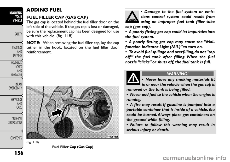
FUEL FILLER CAP (GAS CAP)
The gas cap is located behind the fuel filler door on the
left side of the vehicle. If the gas cap is lost or damaged,
be sure the replacement cap has been designed for use
with this vehicle. (fig. 118)
NOTE:When removing the fuel filler cap, lay the cap
tether in the hook, located on the fuel filler door
reinforcement.
Damage to the fuel system or emis-
sions control system could result from
using an improper fuel tank filler tube
cap (gas cap).
A poorly fitting gas cap could let impurities into
the fuel system.
A poorly fitting gas cap may cause the “Mal-
function Indicator Light (MIL)” to turn on.
To avoid fuel spillage and overfilling, do not “top
off ” the fuel tank after filling. When the fuel
nozzle “clicks” or shuts off, the fuel tank is full.
WARNING!
Never have any smoking materials lit
in or near the vehicle when the gas cap is
removed or the tank is being filled.
Never add fuel to the vehicle when the engine is
running.
A fire may result if gasoline is pumped into a
portable container that is inside of a vehicle.You
could be burned. Always place gas containers on
the ground while filling.
Failure to follow this warning may result in
serious injury or death.
(fig. 118) Fuel Filler Cap (Gas Cap)
156
KNOWING YOUR
VEHICLE
SAFETY
STARTING AND
DRIVING
WARNING LIGHTSAND
MESSAGES
IN AN
EMERGENCY
SERVICING AND
CARETECHNICAL
SPECIFICATIONSCONTENTS