FIAT PANDA 2018 Owner handbook (in English)
Manufacturer: FIAT, Model Year: 2018, Model line: PANDA, Model: FIAT PANDA 2018Pages: 228, PDF Size: 17.05 MB
Page 11 of 228
KEYS
MECHANICAL KEY
The metal insert of the key activates:
the ignition device, the driver's side and
passenger's side door locks (for
versions/markets where provided) and
the luggage compartment lock.
KEY WITH REMOTE
CONTROL
(for versions/markets, where provided)
1)1)1)
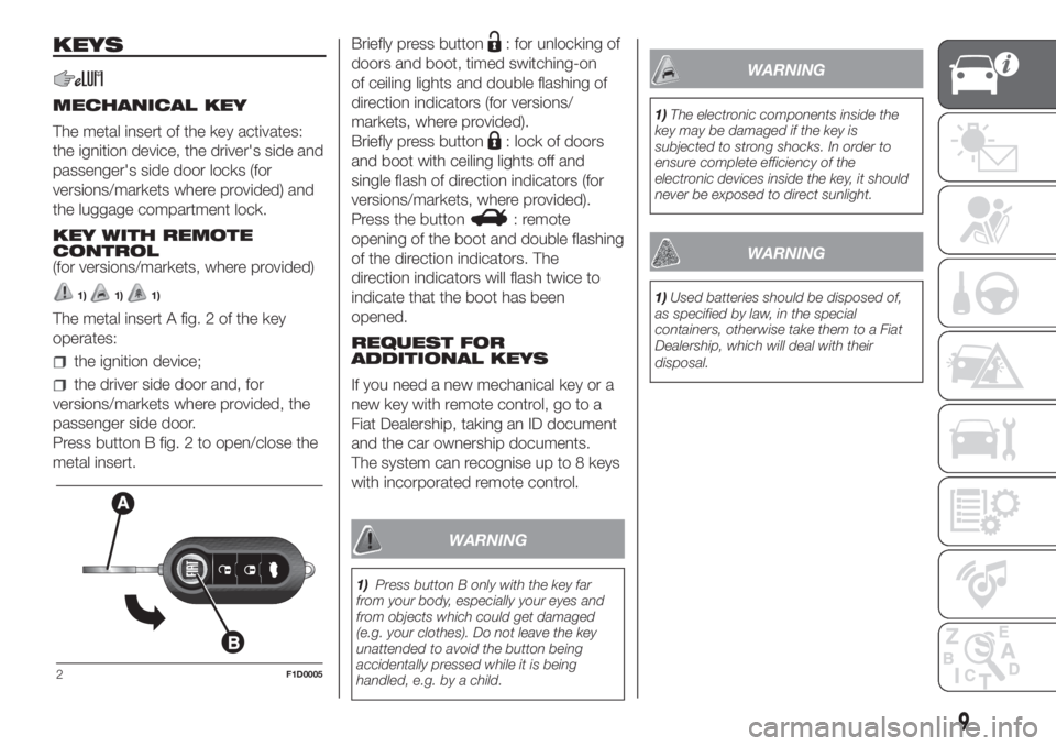
The metal insert A fig. 2 of the key
operates:
the ignition device;
the driver side door and, for
versions/markets where provided, the
passenger side door.
Press button B fig. 2 to open/close the
metal insert.Briefly press button
: for unlocking of
doors and boot, timed switching-on
of ceiling lights and double flashing of
direction indicators (for versions/
markets, where provided).
Briefly press button
: lock of doors
and boot with ceiling lights off and
single flash of direction indicators (for
versions/markets, where provided).
Press the button
: remote
opening of the boot and double flashing
of the direction indicators. The
direction indicators will flash twice to
indicate that the boot has been
opened.
REQUEST FOR
ADDITIONAL KEYS
If you need a new mechanical key or a
new key with remote control, go to a
Fiat Dealership, taking an ID document
and the car ownership documents.
The system can recognise up to 8 keys
with incorporated remote control.
WARNING
1)Press button B only with the key far
from your body, especially your eyes and
from objects which could get damaged
(e.g. your clothes). Do not leave the key
unattended to avoid the button being
accidentally pressed while it is being
handled, e.g. by a child.
WARNING
1)The electronic components inside the
key may be damaged if the key is
subjected to strong shocks. In order to
ensure complete efficiency of the
electronic devices inside the key, it should
never be exposed to direct sunlight.
WARNING
1)Used batteries should be disposed of,
as specified by law, in the special
containers, otherwise take them to a Fiat
Dealership, which will deal with their
disposal.
2F1D0005
9
Page 12 of 228
IGNITION DEVICE
2) 3) 4) 5)
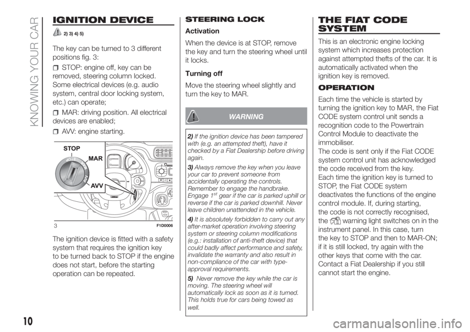
The key can be turned to 3 different
positions fig. 3:
STOP: engine off, key can be
removed, steering column locked.
Some electrical devices (e.g. audio
system, central door locking system,
etc.) can operate;
MAR: driving position. All electrical
devices are enabled;
AVV: engine starting.
The ignition device is fitted with a safety
system that requires the ignition key
to be turned back to STOP if the engine
does not start, before the starting
operation can be repeated.STEERING LOCK
Activation
When the device is at STOP, remove
the key and turn the steering wheel until
it locks.
Turning off
Move the steering wheel slightly and
turn the key to MAR.
WARNING
2)If the ignition device has been tampered
with (e.g. an attempted theft), have it
checked by a Fiat Dealership before driving
again.
3)Always remove the key when you leave
your car to prevent someone from
accidentally operating the controls.
Remember to engage the handbrake.
Engage 1
stgear if the car is parked uphill or
reverse if the car is parked downhill. Never
leave children unattended in the vehicle.
4)It is absolutely forbidden to carry out any
after-market operation involving steering
system or steering column modifications
(e.g.: installation of anti-theft device) that
could badly affect performance and safety,
invalidate the warranty and also result in
non-compliance of the car with type-
approval requirements.
5)Never remove the key while the car is
moving. The steering wheel will
automatically lock as soon as it is turned.
This holds true for cars being towed as
well.
THE FIAT CODE
SYSTEM
This is an electronic engine locking
system which increases protection
against attempted thefts of the car. It is
automatically activated when the
ignition key is removed.
OPERATION
Each time the vehicle is started by
turning the ignition key to MAR, the Fiat
CODE system control unit sends a
recognition code to the Powertrain
Control Module to deactivate the
immobiliser.
The code is sent only if the Fiat CODE
system control unit has acknowledged
the code received from the key.
Each time the ignition key is turned to
STOP, the Fiat CODE system
deactivates the functions of the engine
control module. If, during starting,
the code is not correctly recognised,
the
warning light switches on in the
instrument panel. In this case, turn
the key to STOP and then to MAR-ON;
if it is still locked, try again with the
other keys that come with the car.
Contact a Fiat Dealership if you still
cannot start the engine.3F1D0006
10
KNOWING YOUR CAR
Page 13 of 228
If thewarning light turns on, this
means that the system is running
a self-diagnosis (for example due to a
voltage drop). Should the fault persist,
contact a Fiat Dealership.DOORS
LOCKING/UNLOCKING
DOORS FROM THE
INSIDE
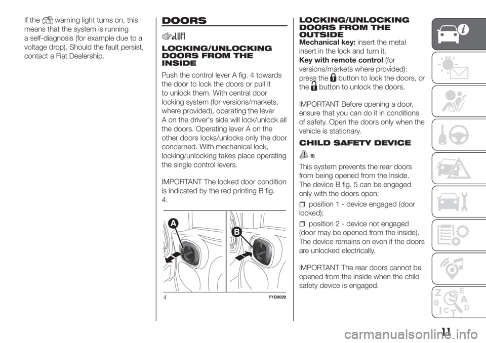
Push the control lever A fig. 4 towards
the door to lock the doors or pull it
to unlock them. With central door
locking system (for versions/markets,
where provided), operating the lever
A on the driver's side will lock/unlock all
the doors. Operating lever A on the
other doors locks/unlocks only the door
concerned. With mechanical lock,
locking/unlocking takes place operating
the single control levers.
IMPORTANT The locked door condition
is indicated by the red printing B fig.
4.LOCKING/UNLOCKING
DOORS FROM THE
OUTSIDE
Mechanical key:insert the metal
insert in the lock and turn it.
Key with remote control(for
versions/markets where provided):
press the
button to lock the doors, or
the
button to unlock the doors.
IMPORTANT Before opening a door,
ensure that you can do it in conditions
of safety. Open the doors only when the
vehicle is stationary.
CHILD SAFETY DEVICE
6)
This system prevents the rear doors
from being opened from the inside.
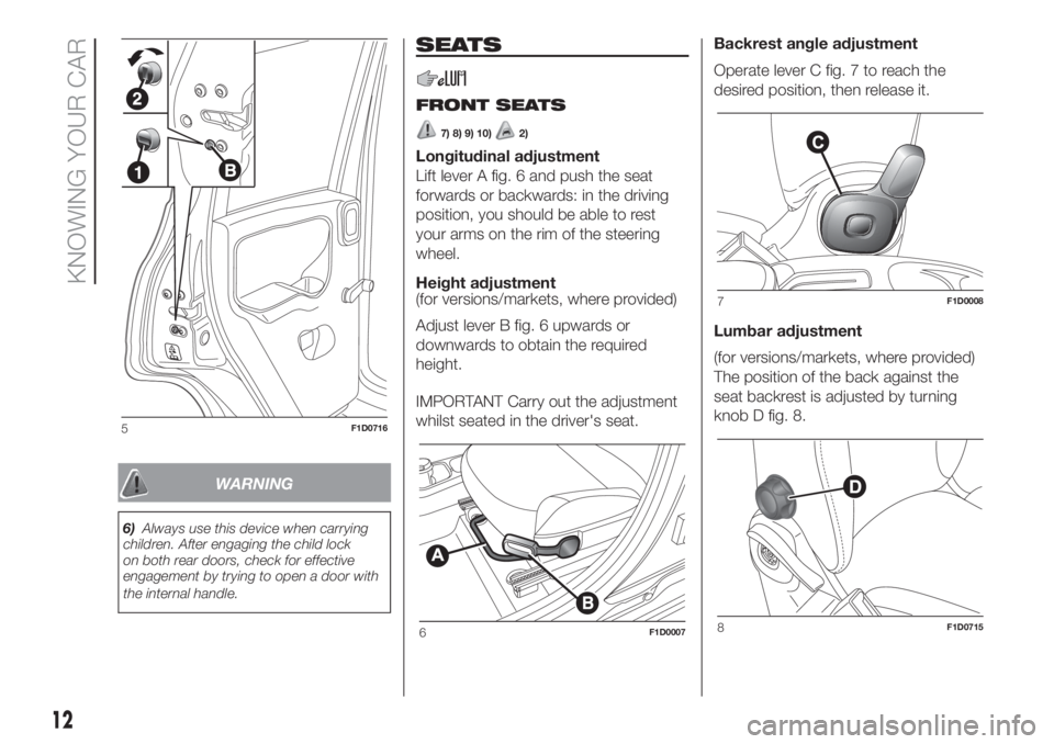
The device B fig. 5 can be engaged
only with the doors open:
position 1 - device engaged (door
locked);
position 2 - device not engaged
(door may be opened from the inside).
The device remains on even if the doors
are unlocked electrically.
IMPORTANT The rear doors cannot be
opened from the inside when the child
safety device is engaged.
4F1D0029
11
Page 14 of 228
WARNING
6)Always use this device when carrying
children. After engaging the child lock
on both rear doors, check for effective
engagement by trying to open a door with
the internal handle.
SEATS
FRONT SEATS
7) 8) 9) 10)2)
Longitudinal adjustment
Lift lever A fig. 6 and push the seat
forwards or backwards: in the driving
position, you should be able to rest
your arms on the rim of the steering
wheel.
Height adjustment
(for versions/markets, where provided)
Adjust lever B fig. 6 upwards or
downwards to obtain the required
height.
IMPORTANT Carry out the adjustment
whilst seated in the driver's seat.Backrest angle adjustment
Operate lever C fig. 7 to reach the
desired position, then release it.
Lumbar adjustment
(for versions/markets, where provided)
The position of the back against the
seat backrest is adjusted by turning
knob D fig. 8.
5F1D0716
6F1D0007
7F1D0008
8F1D0715
12
KNOWING YOUR CAR
Page 15 of 228
FRONT SEAT ELECTRIC
HEATING
(for versions/markets, where provided)
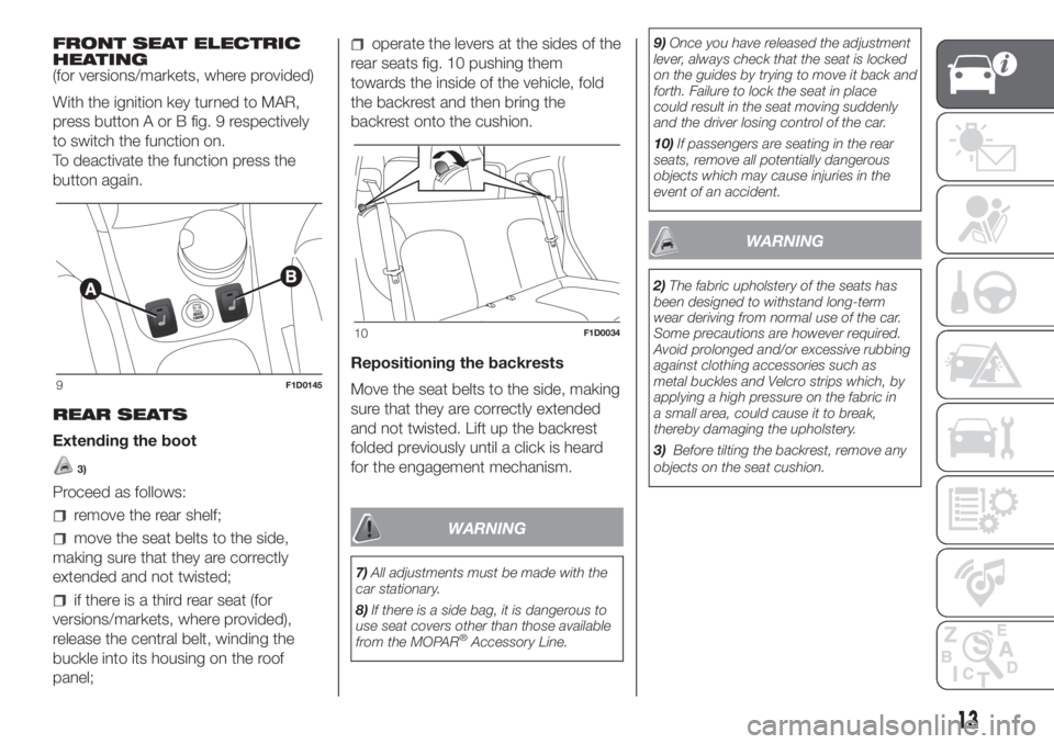
With the ignition key turned to MAR,
press button A or B fig. 9 respectively
to switch the function on.
To deactivate the function press the
button again.
REAR SEATS
Extending the boot
3)
Proceed as follows:
remove the rear shelf;
move the seat belts to the side,
making sure that they are correctly
extended and not twisted;
if there is a third rear seat (for
versions/markets, where provided),
release the central belt, winding the
buckle into its housing on the roof
panel;
operate the levers at the sides of the
rear seats fig. 10 pushing them
towards the inside of the vehicle, fold
the backrest and then bring the
backrest onto the cushion.
Repositioning the backrests
Move the seat belts to the side, making
sure that they are correctly extended
and not twisted. Lift up the backrest
folded previously until a click is heard
for the engagement mechanism.
WARNING
7)All adjustments must be made with the
car stationary.
8)If there is a side bag, it is dangerous to
use seat covers other than those available
from the MOPAR
®Accessory Line.9)Once you have released the adjustment
lever, always check that the seat is locked
on the guides by trying to move it back and
forth. Failure to lock the seat in place
could result in the seat moving suddenly
and the driver losing control of the car.
10)If passengers are seating in the rear
seats, remove all potentially dangerous
objects which may cause injuries in the
event of an accident.
WARNING
2)The fabric upholstery of the seats has
been designed to withstand long-term
wear deriving from normal use of the car.
Some precautions are however required.
Avoid prolonged and/or excessive rubbing
against clothing accessories such as
metal buckles and Velcro strips which, by
applying a high pressure on the fabric in
a small area, could cause it to break,
thereby damaging the upholstery.
3)Before tilting the backrest, remove any
objects on the seat cushion.
9F1D0145
10F1D0034
13
Page 16 of 228
HEAD RESTRAINTS
11) 12)
FRONT HEAD
RESTRAINTS
Upwards adjustment: raise the head
restraint until it clicks into place.
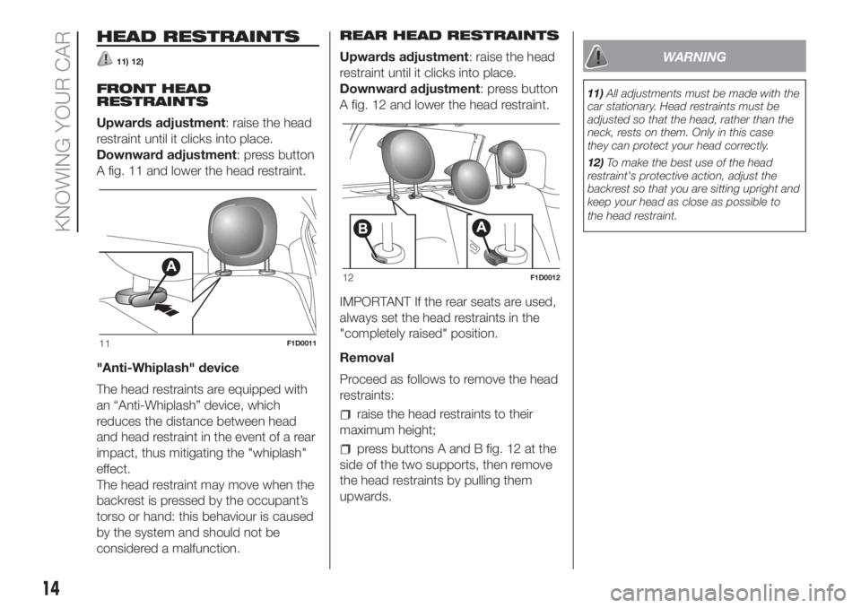
Downward adjustment: press button
A fig. 11 and lower the head restraint.
"Anti-Whiplash" device
The head restraints are equipped with
an “Anti-Whiplash” device, which
reduces the distance between head
and head restraint in the event of a rear
impact, thus mitigating the "whiplash"
effect.
The head restraint may move when the
backrest is pressed by the occupant’s
torso or hand: this behaviour is caused
by the system and should not be
considered a malfunction.REAR HEAD RESTRAINTS
Upwards adjustment: raise the head
restraint until it clicks into place.
Downward adjustment: press button
A fig. 12 and lower the head restraint.
IMPORTANT If the rear seats are used,
always set the head restraints in the
"completely raised" position.
Removal
Proceed as follows to remove the head
restraints:
raise the head restraints to their
maximum height;
press buttons A and B fig. 12 at the
side of the two supports, then remove
the head restraints by pulling them
upwards.
WARNING
11)All adjustments must be made with the
car stationary. Head restraints must be
adjusted so that the head, rather than the
neck, rests on them. Only in this case
they can protect your head correctly.
12)To make the best use of the head
restraint's protective action, adjust the
backrest so that you are sitting upright and
keep your head as close as possible to
the head restraint.
11F1D0011
12F1D0012
14
KNOWING YOUR CAR
Page 17 of 228
STEERING WHEEL
13) 14)
ADJUSTMENTS
The steering wheel can be adjusted
vertically.
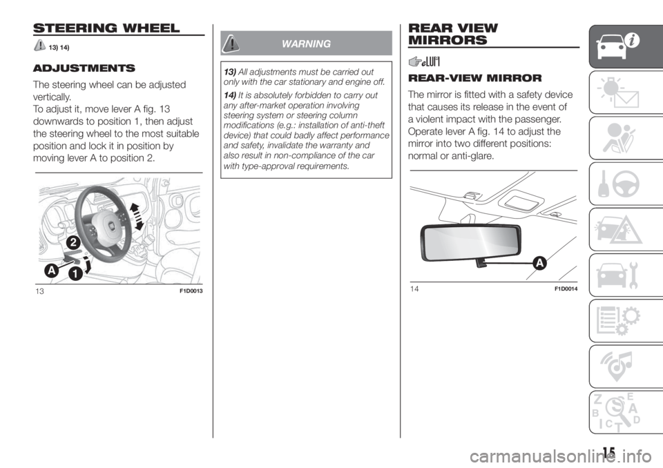
To adjust it, move lever A fig. 13
downwards to position 1, then adjust
the steering wheel to the most suitable
position and lock it in position by
moving lever A to position 2.
WARNING
13)All adjustments must be carried out
only with the car stationary and engine off.
14)It is absolutely forbidden to carry out
any after-market operation involving
steering system or steering column
modifications (e.g.: installation of anti-theft
device) that could badly affect performance
and safety, invalidate the warranty and
also result in non-compliance of the car
with type-approval requirements.
REAR VIEW
MIRRORS
REAR-VIEW MIRROR
The mirror is fitted with a safety device
that causes its release in the event of
a violent impact with the passenger.
Operate lever A fig. 14 to adjust the
mirror into two different positions:
normal or anti-glare.
A
2
1
13F1D001314F1D0014
15
Page 18 of 228
DOOR MIRRORS
15)
Manual adjustment
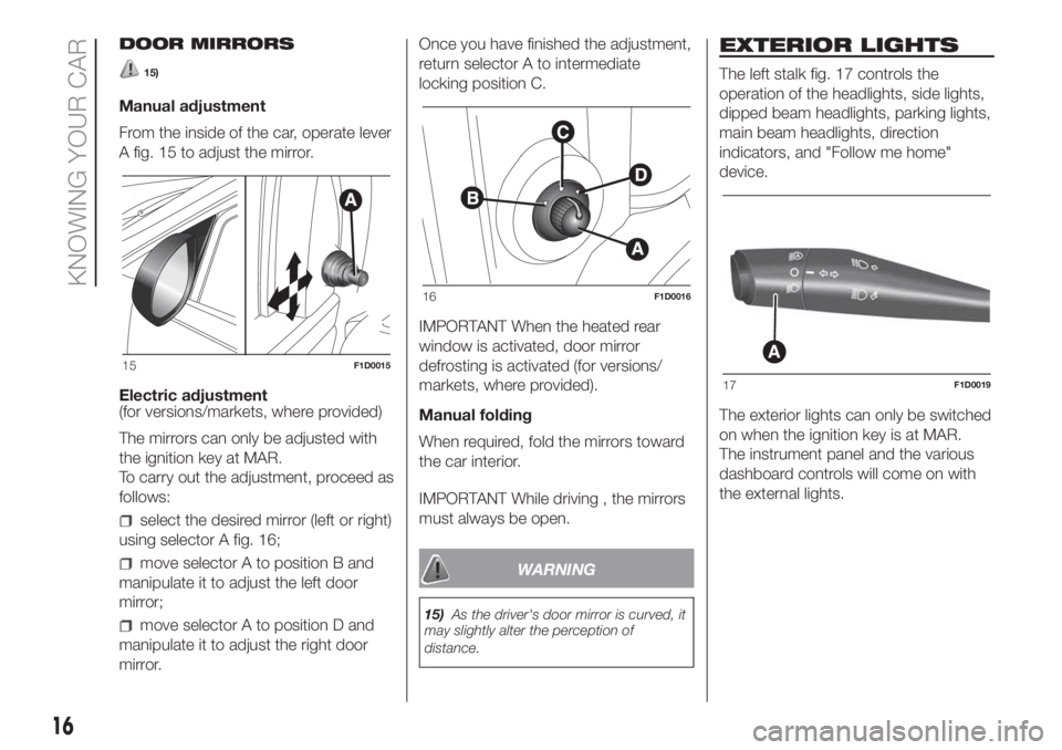
From the inside of the car, operate lever
A fig. 15 to adjust the mirror.
Electric adjustment
(for versions/markets, where provided)
The mirrors can only be adjusted with
the ignition key at MAR.
To carry out the adjustment, proceed as
follows:
select the desired mirror (left or right)
using selector A fig. 16;
move selector A to position B and
manipulate it to adjust the left door
mirror;
move selector A to position D and
manipulate it to adjust the right door
mirror.Once you have finished the adjustment,
return selector A to intermediate
locking position C.
IMPORTANT When the heated rear
window is activated, door mirror
defrosting is activated (for versions/
markets, where provided).
Manual folding
When required, fold the mirrors toward
the car interior.
IMPORTANT While driving , the mirrors
must always be open.
WARNING
15)As the driver's door mirror is curved, it
may slightly alter the perception of
distance.
EXTERIOR LIGHTS
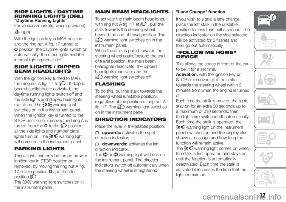
The left stalk fig. 17 controls the
operation of the headlights, side lights,
dipped beam headlights, parking lights,
main beam headlights, direction
indicators, and "Follow me home"
device.
The exterior lights can only be switched
on when the ignition key is at MAR.
The instrument panel and the various
dashboard controls will come on with
the external lights.
15F1D0015
16F1D0016
A
17F1D0019
16
KNOWING YOUR CAR
Page 19 of 228
SIDE LIGHTS / DAYTIME
RUNNING LIGHTS (DRL)
"Daytime Running Lights"
(for versions/markets, where provided)
16) 17)
With the ignition key in MAR position
and the ring nut A fig. 17 turned to
Oposition, the daytime lights switch on
automatically; the other lights and the
internal lighting remain off.
SIDE LIGHTS / DIPPED
BEAM HEADLIGHTS
With the ignition key turned to MAR,
turn ring nut A fig. 17 to
. If dipped
beam headlights are activated, the
daytime running lights switch off and
the side lights and dipped headlights
switch on. The
warning light
switches on in the instrument panel.
When the ignition key is turned to the
STOP position or removed and ring A is
turned from theOto the
position,
all the side lights and number plate
lights turn on. The
warning light
will come on in the instrument panel.
PARKING LIGHTS
These lights can only be turned on with
ignition key in STOP position or
removed, by moving the ring nut A fig.
17 first to positionOand then to
position
.
The
warning light switches on in
the instrument panel.MAIN BEAM HEADLIGHTS
To activate the main beam headlights,
with ring nut A fig. 17 at
, pull the
stalk towards the steering wheel
beyond the end of travel position. The
warning light switches on in the
instrument panel.
When the stalk is pulled towards the
steering wheel again, beyond the end
of travel position, the main beam
headlights deactivate, the dipped
headlights reactivate and the
warning light switches off.
FLASHING
To do this, pull the stalk towards the
steering wheel (unstable position),
regardless of the position of ring nut A
fig. 17. The
warning light switches
on in the instrument panel.
DIRECTION INDICATORS
Place the lever in the (stable) position:
upwards:activates the right
direction indicator;
downwards:activates the left
direction indicator.
The
orwarning light will blink on
the instrument panel. The direction
indicators switch off automatically when
the steering wheel is straightened."Lane Change" function
If you wish to signal a lane change,
place the left stalk in the unstable
position for less than half a second. The
direction indicator on the side selected
will be activated for 5 flashes and
then go out automatically.
"FOLLOW ME HOME"
DEVICE
This allows the space in front of the car
to be lit for a set time.
Activation:with the ignition key on
STOP or removed, pull the stalk
towards the steering wheel within 2
minutes from when the engine is turned
off.
Each time the stalk is moved, the lights
stay on for an extra 30 seconds up to
a maximum of 210 seconds; then
the lights are switched off automatically.
Each time the stalk is operated, the
warning light on the instrument
panel switches on and the display also
shows a message and how long the
function will remain active.
The
warning light comes on when
the stalk is first operated and stays on
until the function is automatically
deactivated. Each time the stalk is
activated it increases the time that the
lights remain on.
17
Page 20 of 228
Deactivation:keep the stalk pulled
towards the steering wheel for more
than two seconds.
REAR FOG LIGHTS
Press the
button, on the dashboard,
to switch on the rear fog lights.
With rear fog lights on, the
warning
light on the instrument panel will come
on at the same time.
FRONT/REAR FOG
LIGHTS
(for versions/markets, where provided)
The fog lights can be activated only
when the dipped beam headlights are
on.
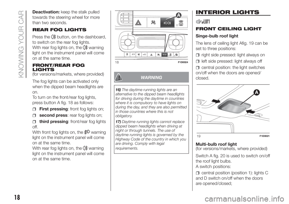
To turn on the front/rear fog lights,
press button A fig. 18 as follows:
First pressing: front fog lights on;
second press: rear fog lights on;
third pressing: front/rear fog lights
off.
With front fog lights on, the
warning
light on the instrument panel will come
on at the same time.
With rear fog lights on, the
warning
light on the instrument panel will come
on at the same time.
WARNING
16)The daytime running lights are an
alternative to the dipped beam headlights
for driving during the daytime in countries
where it is compulsory to have lights on
during the day, and they are also permitted
in those countries where this is not
obligatory.
17)Daytime running lights cannot replace
dipped beam headlights when driving at
night or through tunnels. The use of
daytime running lights is governed by the
Highway Code of the country in which you
are driving. Comply with legal
requirements.
INTERIOR LIGHTS
FRONT CEILING LIGHT
Singe-bulb roof light
The lens of ceiling light Afig. 19 can be
set to three positions:
right side pressed: light always on
left side pressed: light always off
central position: the light switches
on/off when the doors are opened/
closed.
Multi-bulb roof light
(for versions/markets, where provided)
Switch A fig. 20 is used to switch on/off
the roof light bulbs.
A switch positions:
central position (position 1): lights C
and D switch on/off when the doors
are opened/closed;
18F1D0024
19F1D0021
18
KNOWING YOUR CAR