oil FIAT PUNTO 1998 176 / 1.G Owners Manual
[x] Cancel search | Manufacturer: FIAT, Model Year: 1998, Model line: PUNTO, Model: FIAT PUNTO 1998 176 / 1.GPages: 225, PDF Size: 18.54 MB
Page 137 of 225
Fuel system - diesel models 4C*3
Torque wrench settings Nm Ibfft Fuel injection pump roar bracket .. . 29 21 Fuel Injection pump .... 25 18 Fuel Injectors 41 Fuel pipe union nuts .... 30 22 Inlet manifold .... 24 18 Lower oil tiller mounting and injection pump mounting nut ..... .... 71 S2 Turbocnarger to exhaust manifold .... <10 30 Upper Dtl filter mounting end injection pump mounting nut 98 72
1 General information and precautions
General information The fuel system consists of a rear-mounted fust tank, a fuel filter with integral water separator, a fuel injection pump, in|eciors and associated components. A turbocharger is fitted to TDS, TD and TDSX models. Fuel Is drawn from the fuel tank to the fuel Injection pump by a vane-type transfer pump Incorporated in the fuel injection pump. Before reaching tho pump, the fuel passes through a fuel filter, where foreign matter and water aro removed. Excess fuel lubricates the moving components of the pump, and Is then returned to the tank. On turbo models with the Bosch fuel Injection systom, an eiectncally operated heater is incorporated In the fuel filter housing. The fuel injection pump is driven at half-crankshaft speed by the timing belt. The nigh pressure required to inject tho fuel into the compressed air in the swirl chambers Is achlovod by a cam plate acting on a single piston on the Bosch pumo, or by two opposed pistons forced together by rollers running in a cam ring on the Lucas (CAV) pump. Tlie fuel passes through acentral rotor with a single outlet drilling which aligns With ports leading to the Injector pipes. Fuel metering is controlled by a centrifugal governor, which reacts to accelerator pedal
position end engine speed. The governor is linked lo a metering valve, which increases or decreases the amount of fuel delivered at each pumping stroke. On turbocharged models, a separate device also Increases luel delivery with increasing boost pressure. Basic injection timing is determined when the pump is fitted. When the engine is running, it Is varied automatically to suit the prevailing engine speed by a mechanism which turns the cam plate or ring, Tho four fuel injectors proouco a homogeneous spray of fuel Into the swirl chambers located In the cylinder head. The Injectors are calibrated to open end close at critical pressures lo provide efficient and even combustion. Each injector needle is lubricated by fuel, which accumulates In the spring chamber and is channelled to the injection pump return hose by loak-off pipes Bosch or Lucas fuel system components mBy be fitted, depending on the model. Components from the latter manufacturer are marked either CAV. Roto-dlesel or Con-diesel. depending on their date and place of manufacture. With the exception of the fuel filter assembly, replacement components must be of tho same make as those originally fitted. Cold starting is assisted by preheater or glow plugs fitted to each swirl chamber. On the Bosch injection pump, an automatic cold Injection advance device operated through a thermal switch, advances the injection timing by Increasing the fuel pressure. The device operates at coolant temperatures below 55° C,
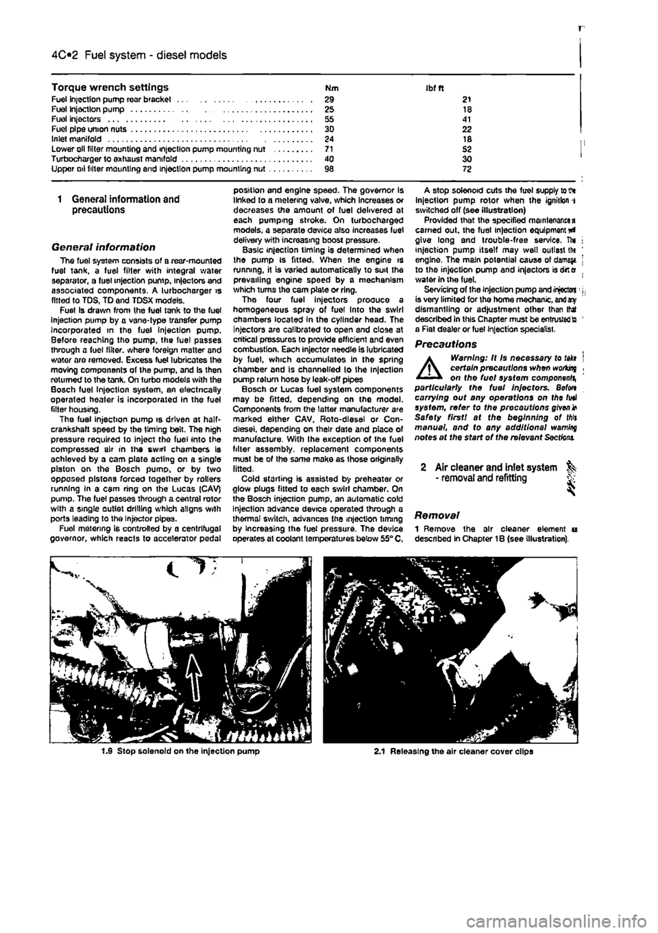
A stop solenoid cuts the fuel supply to V* Injection pump rotor when the ignition i switched off (see illustration) Provided that the specified maintenance* earned out. the fuel injection equipment #» give long and trouble-free service, ft* j injection pump itself may well outlast tlx ' engine, The main potential cause of damage j to the injection pump and injectors is dirt e water in the fuel. 1 Servicing of the injection pump and injectwi: j, is very limited for tho home mechanic, antf dismantling or adjustment other than thtf described In this Chapter must be entrusted to ' a Rat dealer or fuel Injection specialist.
Precautions
A
Warning: It Is necessary to takt I certain precautions when woriong , on the fuel system component^ particularly the fuel Injectors. Befon carrying out any operations on tho fuel system, refer to the precautions given* Safety first! at the beginning of Mis manual, and to any additional wamlrq notes at the start of the relevant
Sections.
2 Air cleaner and inlet system ^ • removal and refitting S
Removal 1 Remove the air cleaner element u described In Chapter 1B (see illustration).
1.9 Stop solenoid on the injection pump 2.1 Releasing the air cleaner cover clips
Page 143 of 225
Fuel system - diesel models 4C*3
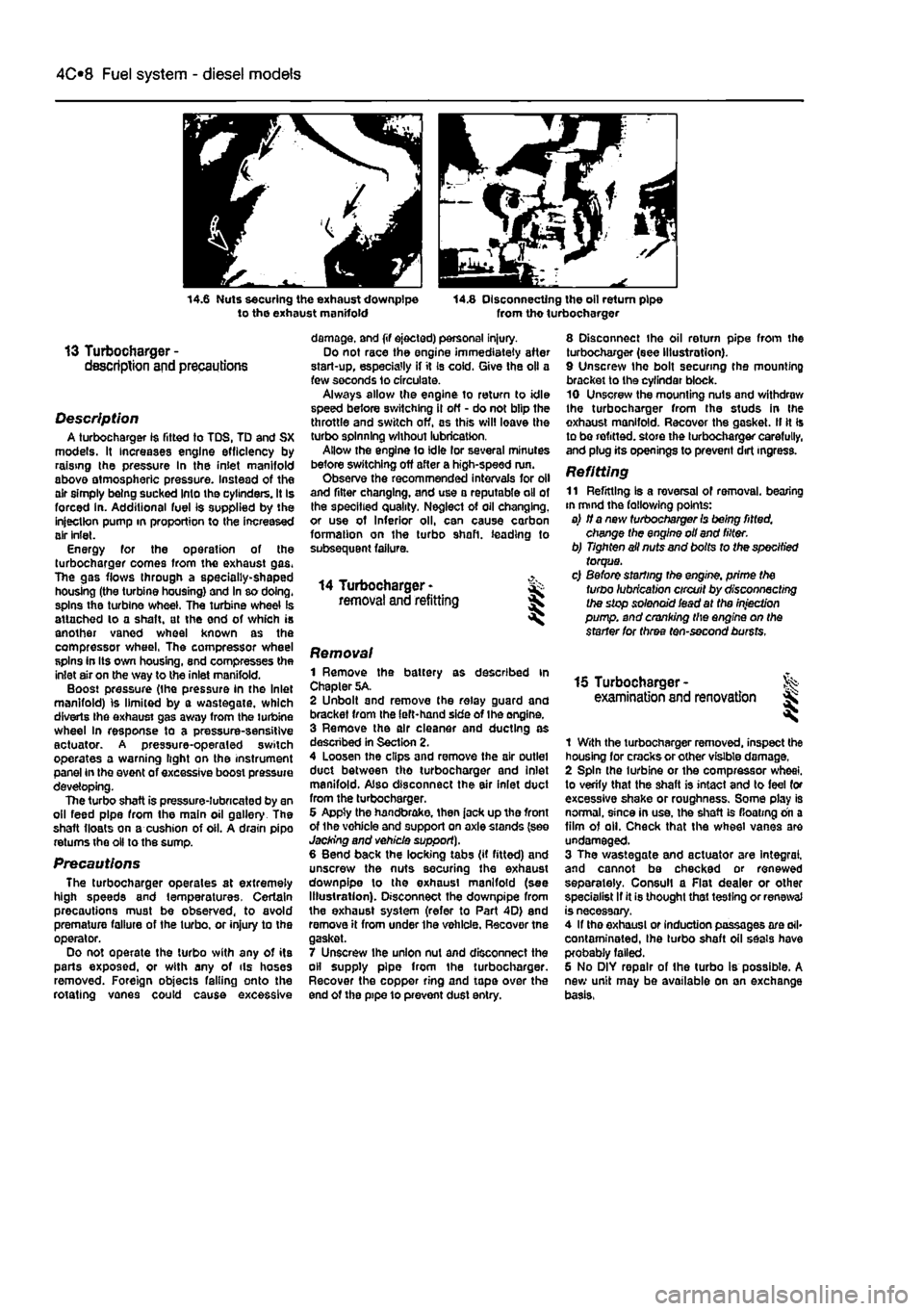
14.6 Nuts securing the exhaust downpipe to the exhaust manifold 14.8 Disconnecting the oil return pipe from tho turbocharger
13 Turbocharger -description and precautions
Description A turbocharger 1$ fitted to TDS, TD and SX models. It increases engine efficiency by raising the pressure In the inlet manifold above atmospheric pressure. Instead of the air simply being sucked Into the cylinders. It Is forced in. Additional fuel is supplied by the injection pump in proportion to the increased air inlet. Energy for the operation of the turbocharger comes from the exhaust gas. The gas flows through a specially-shaped housing (the turbine housing) and In so doing, spins the turbine wheel. The turbine wheel is attached lo a shaft, at the end of which is another vaned wheel known as the compressor wheel, The compressor wheel spins in Its own housing, snd compresses the inlet air on the way to the inlet manifold. Boost pressure (the pressure in the Inlet manifold) is limited by a wastegate, which diverts Ihe exhaust gas away from the turbine wheel In response to a pressure-sensitive actuator. A pressure-operaled switch operates a warning light on the instrument panel in the event of excessive boost pressure developing. The turbo shaft is pressure-lubricated by an oil feed pipe from the main oil gallery The shaft floats on a cushion of oil. A drain pipo returns the oil to the sump.
Precautions The turbocharger operates at extremely high speeds and temperatures. Certain precautions must be observed, to avoid premature failure of the turbo, or injury to the operator. Do not operate the turbo with any of its parts exposed, or with any of ils hoses removed. Foreign objects falling onto the rotating vanes could cause excessive
damage, and (if ejected) personal injury. Do not race the engine immediately after start-up, especially if it Is cold. Give the oil a few seconds lo circulate. Always allow the engine to return to idle speed before switching il off - do not blip the throttle and switch off, as this will leave the turbo spinning without lubrication. Allow the engine to idle lor several minutes before switching off after a high-speed run. Observe the recommended intervals for oil and filter changing, and use a reputable oil of the specified quality. Neglect of oil changing, or use of Inferior oil, can cause carbon formation on the turbo shaft, leading to subsequent failure.
14 Turbocharger -removal and refitting
8 Disconnect the oil return pipe from the turbocharger (see Illustration). 9 Unscrew the bolt securing the mounting bracket to the cyfindar block. 10 Unscrew the mounting nuts and withdraw the turbocharger from the studs in Ihe exhaust manifold. Recover the gasket. II It Is to be refitted, store the turbocharger carefully, and plug its openings to prevent dirt ingress.
Refitting 11 Refitting Is a reversal of removal, bearing in mind the fallowing points: a) if a new turbocharger Is being fitted, change the engine oil and filter. b) Tighten ail nuts and bolts to the specified torque. c) Before starting the engine, prime the turbo lubrication circuit by disconnecting the stop solenoid iead at the injection pump, and cranking the engine on the starter for three ten-second bursts.
Removal 1 Remove the battery as described in Chapter 5A. 2 Unbolt and remove the relay guard and bracket from the left-hand side of Ihe engine. 3 Remove the air cleaner and ducting as descnbed in Section 2. 4 Loosen the clips and remove the air outlet duct between tho turbocharger and inlet manifold. Also disconnect the air inlet duct from the turbocharger. 6 Appty the handbrake, then jack up tho front of the vohicle and support on axle stands (see Jacking and vehicle support). 6 Bend back the locking tabs (if fitted) and unscrew the nuts securing the exhaust downpipe lo the exhaust manifold (see Illustration). Disconnect the downpipe from the exhaust system (refer to Part 4D) end remove it from under the vehicle. Recover tne gasket. 7 Unscrew ihe union nut and disconnect the oil supply pipe from the turbocharger. Recover the copper ring and tape over the end of the pipe 10 prevent dust entry.
15 Turbocharger -examination and renovation l
1 With the turbocharger removed, inspect the housing for cracks or other visible damage. 2 Spin the turbine or the compressor wheel, to verify that the shaft is intact and to feel for excessive shake or roughness. Some play is normal, since in use, the shaft is floating on a film of oil. Check that the wheel vanes are undamaged. 3 The wastegate and actuator are Integral, and cannot be checked or renewed separately. Consul! a Flat dealer or other specialist If it is thought that testing or renewal is necessary. 4 If tho exhaust or induction passages are ail* contaminated, Ihe turbo shaft oil seals have probably failed. 6 No DIY repair of the turbo is possible. A new unit may be available on an exchange basis,
Page 144 of 225
4D«1
Chapter 4 Part D:
Exhaust and emission control systems
Contents
Catalytic converter - general Information and precautions 7 Crankcase emission system • general information 3 Evaporative loss emission control system • information and component renewal 2
Degrees of difficulty
Exhaust manifold - removal and refitting 5 Exhaust system - general information and component renewal .... 6 General information 1 Lambda oxygen sensor - removal and refitting 4
Easy, suitable
tor novice with fittie ^
1 experience
Fairly easy, suitable for beginner with ^ some experience ^
Fairiy dfficult, lb suitable for competent ^ DIY mechanic ^
Difficult, suitable for experienced DIY ^ mechanic
Very difficult, ^ suitable far expert DIY or professional
Specifications
Torque wrench settings Exhaust down pipe to manifold Exhaust manifold Exhaust system mounting Exhaust to catalytic converter: M8 M10x1.25
Nm Ibfft 24 18 24 18 27 20
24 18 40 30 53 39
1 General information
Emission control systems All petrol engine models use unleaded petrol and are controlled by engine management systems that are 'tuned' to give the best compromise between driveability. luel consumption and exhaust emission production. In addition, a number of systems are fitted that help to minimise other harmful emissions: a crankcase emission-control system (petrol models only) that reduces the release of pollutants from the crankcase, an evaporative loss emission control system (petrol models only) to reduce the release of hydrocarbons from the fuel tank, a catalytic converter (petrol and diesel models) to reduce exhaust gas pollutants, and an Exhaust Gas Recirculation (EGR) system (turbo diesel models only) to reduce exhaust emissions. Crankcase emission control To reduce the emission of unburned hydrocarbons from the crankcase Into the atmosphere, the engine is sealed and the blow-by gases and oil vapour are drawn from inside the crankcase, through a flame trap.
into the inlet tract to be burned by the engine during normal combustion. Under conditions of high manifold depression (idling, deceleration) the gases will by sucked positively out of the crankcase. Under conditions of low manifold depression (acceleration, full-throttle running) ihe gases are forced out of the crankcase by the (relatively) higher crankcase pressure: if the engine is worn, the raised crankcase pressure (due to increased blow-by) will cause some of the flow to return under all manifold conditions. Exhaust emission control -petrol models To minimise the amount of pollutants which escape Into the atmosphere, a catalytic converter is fitted In the exhaust system. The fuel system is of the closed-loop type, in which a Lambda (or oxygen) sensor In the exhaust system provides the engine management system ECU with constant feedback, enabling the ECU to adjust the air/fuel mixture to optimise combustion. The Lambda sensor has a heating element built-in that Is controlled by the ECU through the Lambda sensor relay to quickly bring the sensor's tip to Its optimum operating temperature. The sensor's tip Is sensitive to oxygen and relays a voltage signal to the ECU
that varies according on the amount of oxygen In the exhaust gas. If the inlet air/fuel mixture is too rich, the exhaust gases are low in oxygen so the sensor sends a low-voltage signal, the voltage rising as the mixture weakens and the amount of oxygen rises In the exhaust gases. Peak conversion efficiency of all major pollutants occurs if the inlet air/fuel mixture Is maintained at the chemlcally-con*ect ratio for the complete combustion of petrol of 14.7 parts (by weight) of air to
1
part of fuel (the stoichiometric ratio). The sensor output voltage alters in a large step at this point, the ECU using the signal change as a reference point and correcting the Inlet air/fuel mixture accordingly by altering the fuel Injector pulse width. Exhaust emission control -diesel models An oxidation catalyst is fitted in the exhaust system of all diesel engine models. This has the effect of removing a large proportion of the gaseous hydrocarbons, carbon monoxide and particulates present in the exhaust gas. An Exhaust Gas Recirculation (EGR) system Is fitted to all turbo diesel engine models. This reduces the level of nitrogen oxides produced during combustion by Introducing a proportion of the exhaust gas back into the inlet manifold, under certain engine operating
Page 147 of 225
4D*4 Exhaust and emission control systems
d) DO NOT push- or tow-start the car - this will soak the catalytic converter
in
unbumed fuel, causing It to overheat when the engine does start. e) DO NOT switch off the ignition at high engine speeds. f) DO NOT use fuel or engine oil additives -these may contain substances harmful to the catalytic converter. g) DO NOT continue to use the car If
the
engine bums oil to the extent of leaving
a
visible trail of blue smoke.
h) Remember that the catalytic converter operates at very high temperatures. DO NOT, therefore, park the car in dry undergrowth, over long grass or piles of deed leaves after a long run. I) Remember that the catalytic converter is FRAGILE - do not strike it with tools during servicing work, j} In some cases a sulphurous smell
pike
that of rotten eggs) may be noticed from the exhaust. This Is common to many catalytic converter-equipped cars and
once the car has covered a few
thousand
miles tha problem should
disappear,
k)
The
catalytic converter, used on a
weW*
maintained and well-driven car, should las for between
SO
000 and
100
000
miles-If
the converter is no longer effective It
must
be renewed.
Diesel models Refer to the information given in parts i,
g, h
and I of the petrol models information given above.
Page 148 of 225
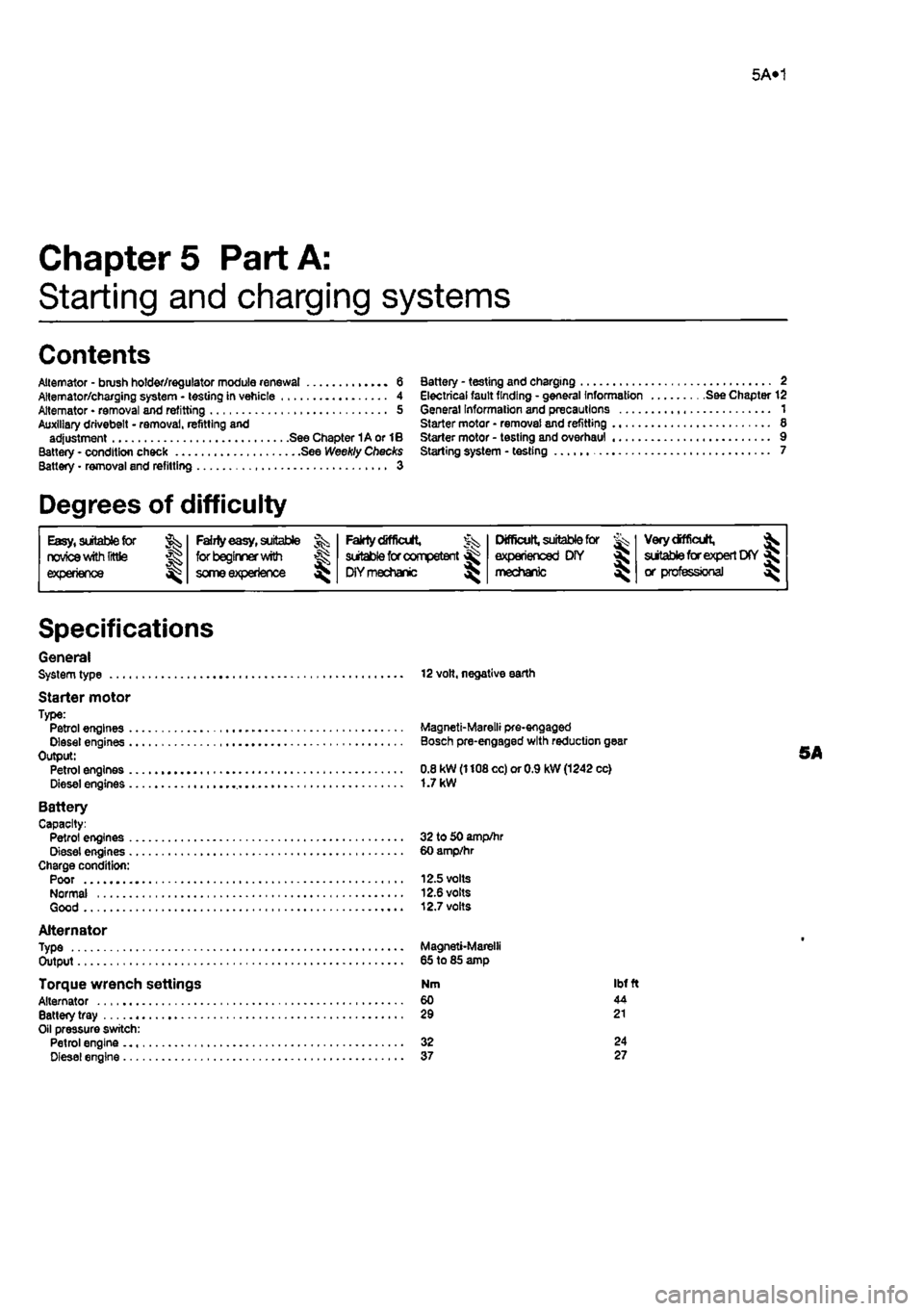
5A»1
Chapters Part A:
Starting and charging systems
Contents
Alternator - brush holder/regulator module renewal 6 Alternator/charging system • testing in vehicle 4 Alternator • removal and refitting 5 Auxiliary drivebelt • removal, refitting and adjustment See Chapter 1A or 1B Battery • condition check See Weekly Checks Battery • removal and refitting 3
Battery - testing and charging 2 Electrical fault finding • general Information See Chapter 12 General Information and precautions 1 Starter motor • removal and refitting 8 Starter motor - testing and overhaul 9 Starting system - testing 7
Degrees of difficulty
Easy, suitable for & novice with Tittle jg experience ^
Fairly easy, suitable ^ for beginner with some experience 3J
Fairly tfifftait, J^ sutable for competent ^ DIYmechanic ^
Difficult, suitable for ^ experienced D!Y mechanic ^
Verydtfficult, jk stitable far expert DfY X or professional ^
Specifications
General System type 12 volt, negative earth
Starter motor Type: Petrol engines Magneti-Marelli pre-engaged Diesel engines Bosch pre-engaged with reduction gear Output: 5A Petrol engines 0.8 kW (1108 cc) or 0.9 kW (1242 cc) Diesel engines 1.7 kW
Battery Capacity: Petrol engines 32 to 50 amp/hr Diesel engines 60 amp/hr Charge condition: Poor 12.5 volts Normal 12.6 volts Good 12.7 volts
Alternator Type Magneti-Marelli Output 65 to 85 amp
Torque wrench settings Nm ibt ft Alternator 60 44 Battery tray 29 21 Oil pressure switch: Petrol engine 32 24 Diesel engine 37 27
Page 153 of 225
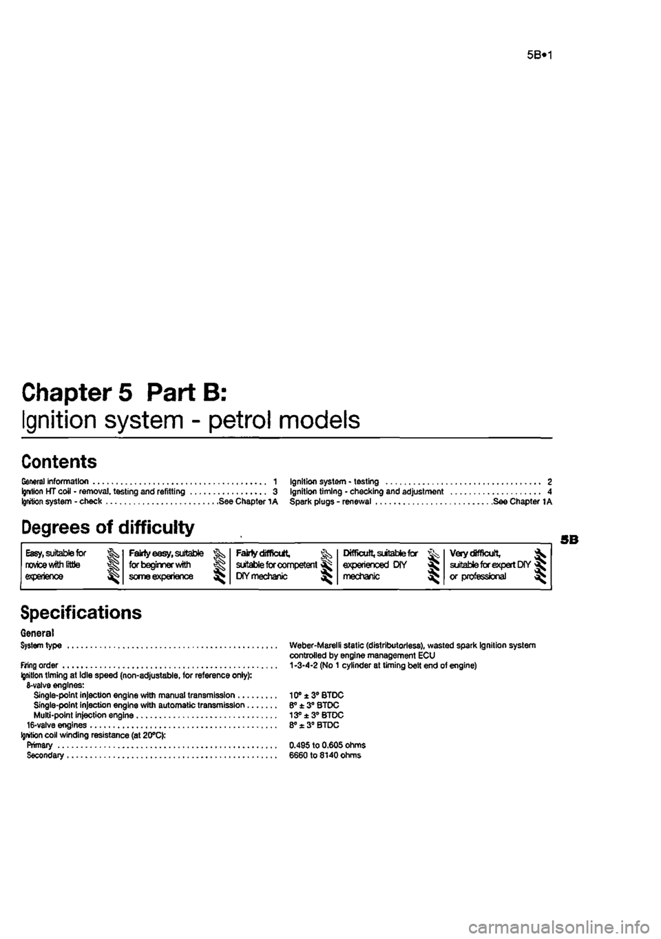
5B*1
Chapters PartB:
Ignition system - petrol models
Contents
General information 1 Ignition system - testing 2 Ignriton HT coil - removal, testing and refitting 3 Ignition timing - checking and adjustment 4 Igrrtion system - check See Chapter 1A Spark plugs - renewal See Chapter 1A
Degrees of difficulty
Easy,
suitable for Falrty easy, sulabte Fafety difficult, suitable for competent Difficult, suitable for Very difficult, ^ novice with littie
1
for beginner with Fafety difficult, suitable for competent experienced DIY suitable for expert DIY or professional ^ expenence 1 some experience DIY mechanic mechanic *
suitable for expert DIY or professional ^
Specifications
General System type
firing order Ignition timing at Idle speed (non-adjustable, for reference onlyy. 6-valve engines: Single-point injection engine with manual transmission .... Single-point injection engine with automatic transmission.. Multi-point injection engine 16-valve engines
Ignition
coil winding resistance (at 20°C): Primary Secondary
Weber-Marelli static (distributorless), wasted spark Ignition system controlled by engine management ECU
1
-3-4-2 (No 1 cylinder at timing belt end of engine)
10® ± 3° BTDC 6° ± 3° STDC 13° ±3° BTDC 8° x 3° BTDC
0.495 to 0.605 ohms 6660 to 8140 Ohms
Page 154 of 225
5B*2 Ignition system - petrol models
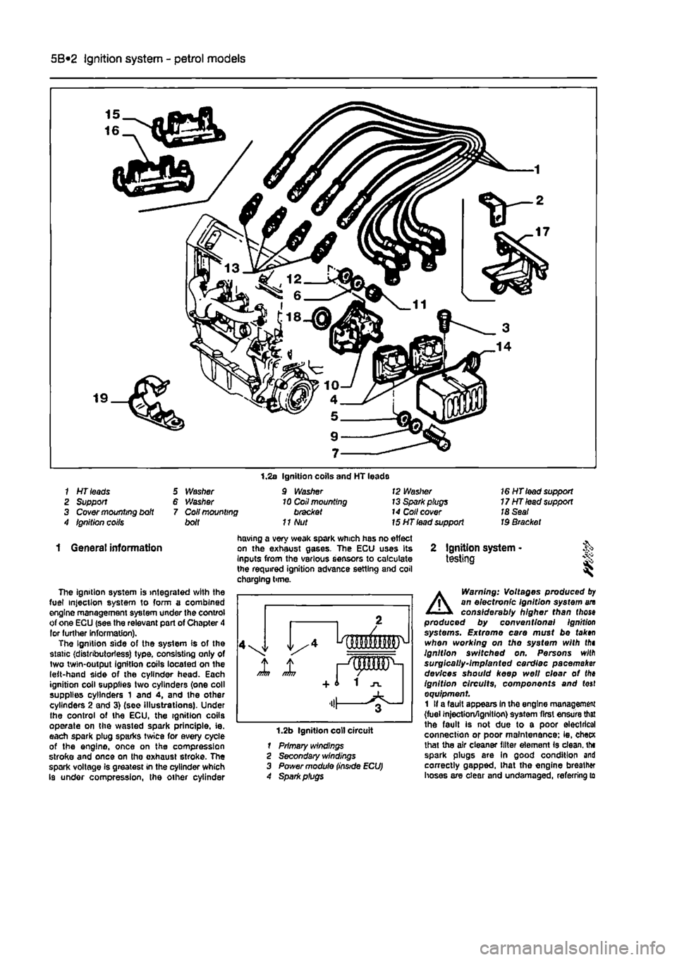
1 HT leads 2 Support 3 Cover mounting bdt 4 Ignition coifs
5 Washer 6 Washer 7 Coil mounting bolt
1.2s Ignition coils and HT leads 9 Washer 10 Coil mounting bracket
11
Nut
12 Waslrer 13 Spark plugs 14 Coll cover 15 HT lead support
16 HT lead support 17HTlead support 18 Seat Id Bracket
1 General information
The ignition system is integrated with the fuel injection system to form a combined engine management system under the control of one ECU (see the relevant part of Chapter 4 lor further Information). The Ignition side of the system is of the static (distributorless) type, consisting only of two twin-output Ignition coils located on the left-hand side of the cylinder head. Each ignition coil supplies two cylinders (one coll supplies cylinders 1 and 4, and the other cylinders 2 and 3) (see Illustrations). Under the control of the ECU, the ignition coils operate on the wasted spark principle, ie. each spark plug sparks twice for every cycle of the engine, once on the compression stroke and once on tho exhaust stroke. The spark voltage is greatest in the cylinder which Is under compression, the other cylinder
having a very weak spark which has no effect on the exhaust gases. The ECU uses Its Inputs from the various sensors to calculate the required ignition advance setting and coil chorging time.
1.2b Ignition coll circuit 1 Primary windings 2 Secondary windings 3 Power module
2 Ignition system -testing i
A
Warning: Voltages produced
by
an electronic Ignition system an considerably higher than (hose produced by conventional Ignition systems. Extreme care must be tak»n when working on tho system with thi Ignition switched on. Persons wilfl surgically-implanted cardiac pacemaker devices should keep well clear ot the ignition circuits, components and (oaf equipment 1 If a fault appears In the engine management (fuel injection/ignition) system first ensure that the fault is not due to a poor electrical connection or poor maintenance: ie, checK lhat the air cleaner filter element is clean, tht spark plugs are In good condition and correctly gapped, lhat the engine breather hoses are clear and undamaged, referring to
Page 155 of 225
Ignition system - petrol models 5B®3
Chapter 1A tor further information. Also check tnat tha accelerator cable is correctly adjusted
as
described in the relevant part of Chapter 4. If the engine is running very roughly, check the compression pressures and the valve clearances as descnbed In the relevant parts of Chapters 1 and 2. 2
H
these checks fall to reveal the cause of the problem, the vehicle should be taken to a suitably equipped Fiat dealer for testing. A wiring block connector Is Incorporated in the engine management circuit Into which a special electronic diagnostic tester can be plugged. The tester will locate the fault quickly and simply alleviating the need to test all the system components Individually which is a time consuming operation that carries a high risk of damaging the ECU. 3 The only Ignition system checks which can
oe
earned out by the home mechanic are those cescribed in Chapter 1A, relating to the spark plugs, and the ignition coll test descnbed In this Chapter. If necessary, the system wiring and wiring connectors can oe checked as descnbed in Chapter 12, Section 2, ensuring that the ECU wiring connector(s) have first
been
disconnected.
3 Ignition HT coil - ^ removal, testing and refitting
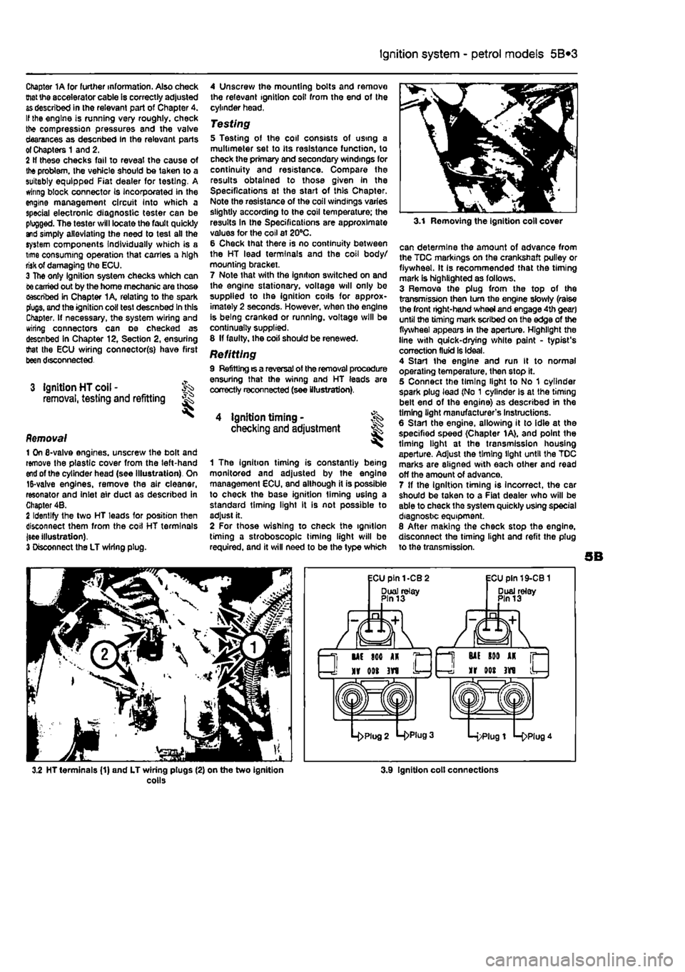
Removal 1 On 6-valve engines, unscrew the boll and remove the plastic cover from the left-hand
end
of the cylinder head (see Illustration). On 15-valve engines, remove the air cleaner, resonator and Inlet air duct as described in Chapter 4B. 2 Identify the two HT leads for position then disconnect them from the coil HT terminals jsee illustration). 3 Disconnect the LT wiring plug.
4 Unscrew the mounting bolts and remove the relevant ignition coil from the end of the cylinder head,
Testing 5 Testing of the coil consists of using a multimeter set to its resistance function, to check the primary and secondary windings for continuity and resistance. Compare the results obtained to those given In the Specifications at the start of this Chapter. Note the resistance of the coil windings varies slightly according to the coil temperature; the results In the Specifications are approximate values for the coil at 20°C. 6 Check that there is no continuity between the HT lead terminals and the coil body/ mourning bracket. 7 Note that with the ignition switched on and the engine stationary, voltage will only be supplied to the ignition cotls for approx-imately 2 seconds. However, when tho engine is being cranked or running, voltage will be continually supplied. 8 If faulty, the coil should be renewed.
Refitting 9 Refitting ts a reversal of the removal procedure ensuring that the winng and HT leads are correctly reconnected (see illustration).
4 ignition timing • checking and adjustment
1 The Ignition timing is constantly being monitored and adjusted by the engine management ECU, and although it is possible to check the base ignition liming using a standard timing light It is not possible to adjust it. 2 For those wishing to check the ignition timing a stroboscope timing light will be required, and it will need to be the type which
3.1 Removing the ignition coll cover
can determine the amount of advance from the TDC markings on the crankshaft pulley or flywheel. It Is recommended that the timing mark is highlighted as follows. 3 Remove the plug from the top of the transmission then turn tho engine slowly (raise the front right-hand wheel and engage 4th gear) until the timing mark scribed on the edge of the flywheel appears in the aperture. Highlight the line with quick-drying white paint - typist's correction fluid is ideal. 4 Start the engine and run It to normal operating temperature, then stop it. 5 Connect the timing light to No 1 cylinder spark plug lead (No 1 cylinder Is at the timing belt end of the engine) as described in the timing light manufacturer's Instructions. 6 Start the engine, allowing it to idle at the specified speed (Chapter 1A), and point the timing light at the transmission housing aperture. Adjust the timing light until the TDC marks are aligned with each other and read off the amount of advance. 7 If the ignition timing is incorrect, the car should be taken to a Fiat dealer who will be able to check the system quickly using special diagnostic equipment. 8 After making the check stop the engine, disconnect the timing light and refit the plug to the transmission.
3.2 HT terminals (1) and LT wiring plugs (2) on the two ignition colls 3.9 Ignition colt connections
Page 160 of 225
Clutch 6*3
6 WorWng inside the vehicle, extract the split pin and remove the washer securing the master cylinder pushrod to the clutch pedal. Dsoonnect the pushrod from the pivot. 7 Have an assistant support the master cylinder In the engine compartment, then unscrew the mounting bolts. Withdraw the master cylinder from the engine compartment, 8 II is not possible to obtain an overhaul kit from Flat however some motor factors may be abls to supply one. Follow the Instructions with the repair kit if obtained.
Refitting 9 Refit the clutch master cylinder by following ihe removal procedure In reverse, noting the following. a) Apply a
Utile
high-melting point grease to the clutch pedal pivot. b) Tighten the mounting bolts and union nut securely. cj Fit a new split pin to the pushrod. d) Where removed, refit the alternator
as
described In Chapter 5A e) On completion bleed the clutch hydraulic system as descnbed in Section
A.
7 Clutch assembly -
removal,
inspection
and
refitting
S Clutch slave cylinder-removal and refitting
Note: This procedure applies to models fitted
ivrth
the hydraulically-operated clutch release mechanism. Note: Refer to the warning at the beginning
of
Section A regarding the hazards of working
with
hydraulic fluid.
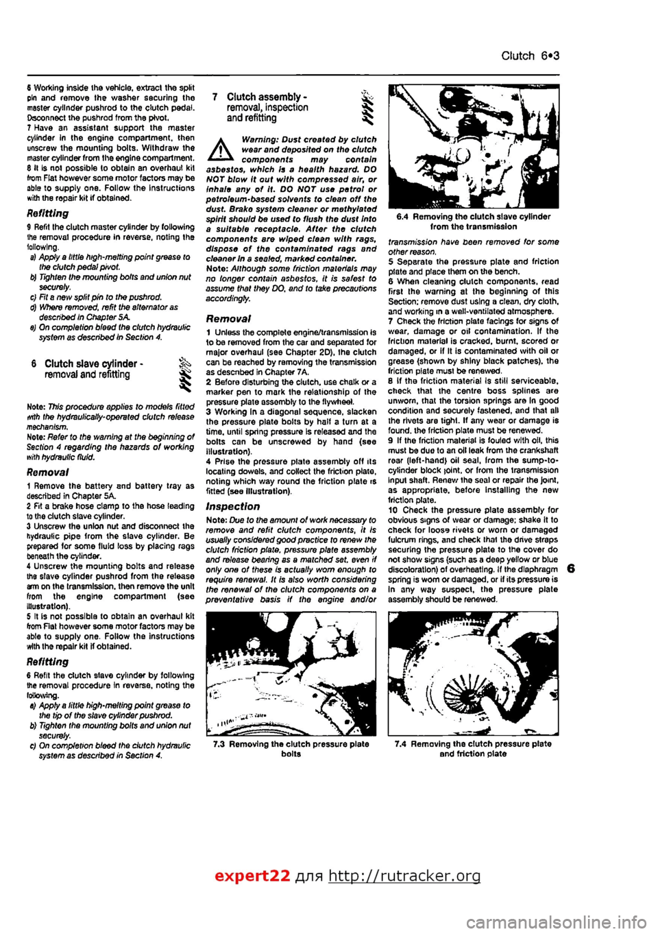
Removal 1 Remove the battery and battery tray as described in Chapter 5A. 2 Fit a brake hose clamp to tha hose leading to the clutch slave cylinder. 3 Unscrew the union nut and disconnect the hydraulic pipe from the slave cylinder. Be prepared for some fluid loss by placing rags beneath the cylinder. 4 Unscrew the mounting bolts and release the slave cylinder pushrod from the release am on the transmission, then remove the unit from the engine compartment (see Illustration). 5 It is not possible to obtain an overhaul kit from Flat however some motor factors may be able to supply one. Follow tha instructions with the repair kit if obtained.
Refitting 6 Refit the clutch slave cylinder by following the removal procedure In reverse, noting the following. a) Apply a little high-melting point grease to the tip of the slave cylinder pushrod. b) Tighten the mounting bolts and union nut securely. c) On completion bleed the dutch hydraulic system as described in Section A.
A
Warning: Dust created by clutch wear and deposited on the clutch components may contain asbestos, which Is a health hazard. DO NOT blow it out with compressed air, or inhale any of it. DO NOT use petrol or petroleum-based solvents to clean off the dust. Brake system cleaner or methylated spirit should be used to flush the dust Into a suitable receptacle. After the clutch components are wiped clean with rags, dispose of the confam/nafed rags and cleaner In a sealed, marked container. Note: Although some friction materials may no longer contain asbestos, it is safest to assume that they DO. and to take precautions accordingly.
Removal 1 Unless the complete engine/transmission is to be removed from the car and separated for major overhaul (see Chapter 2D), Ihe clutch can be reached by removing the transmission as descnbed in Chapter 7A, 2 Before disturbing the clutch, use chalk or a marker pen to mark the relationship of the pressure plate assembly to the flywheel. 3 Working In a diagonal sequence, slacken the pressure plate bolts by half a turn at a time, until spring pressure Is released and the bolls can be unscrewed by hand (see Illustration). 4 Prise the pressure piate assembly off its locating dowels, and collect the friction plate, noting which way round the friction plate is fitted (see Illustration).
Inspection Note: Due to the amount of work necessary to remove and refit clutch components, It is usually considered good practice to renew the clutch friction plate, pressure plate assembly and release bearing as a matched set. even if only one of these is actually worn enough to require renewal. It Is also worth considering the renewal of the clutch components on a preventative basis if the engine and/or
6.4 Removing the clutch slave cylinder from the transmission fransmj'ss/on have been removed for some other reason. 5 Separate the pressure plate and friction plate and place them on the bench. 6 When cleaning clutch components, read first the warning at the beginning of this Section; remove dust using a clean, dry cloth, and working in a well-ventilated atmosphere. 7 Check the friction plats facings for signs Of wear, damage or oil contamination. If the friction material is cracked, burnt, scored or damaged, or if It is contaminated with oil or grease (shown by shiny black patches), the friction plate must be renewed. 8 If tho friction material Is still serviceable, check that the centre boss splines are unworn, that the torsion springs are In good condition and securely fastened, and that all the rivets are tight. If any wear or damage is found, the friction plate must be renewed. 9 If the friction material is fouled with oil, this must be duo to an oil leak from the crankshaft rear (left-hand) oil seal, from the sump-to-cytinder block joint, or from the transmission Input shaft. Renew tha soal or repair the Joint, as appropriate, before Installing the new friction plate. 10 Check tha pressure plate assembly for obvious signs of wear or damage; shake it to check for looss rivets or worn or damaged fulcrum rings, and check thai the drive straps securing the pressure plate to the cover do not show signs (such as a deep yellow or blue discoloration) of overheating. If the diaphragm spring is worn or damaged, or if its pressure is In any way suspect, the pressure plate assembly should be renewed.
7.3 Removing the clutch pressure plate bolts 7.4 Removing the clutch pressure plate and friction plate
expert22 {
a http://rutracker.org
Page 161 of 225
6*4 Clutch
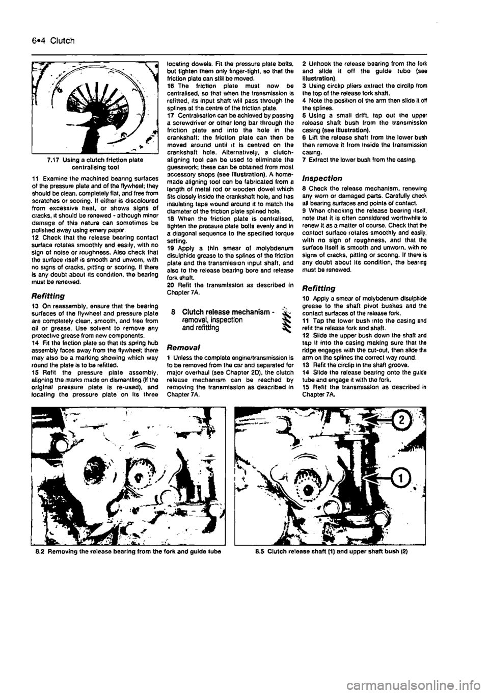
7.17 Using a clutch friction plate centralising toot 11 Examine the machined beanng surfaces of the pressure plate and of the flywheel; they should be clean, completely flat, and free from scratches or scoring. If either is discoloured from excessive heat, or shows signs of cracks, it should be renewed - although minor damage of this nature can sometimes be polished away using emery paper 12 Check that the release bearing contact surface rotates smoothly and easily, with no sign of noise or roughness. Also check that the surface itself is smooth and unworn, with no signs of cracks, pitting or scoring. If there Is any doubt about its condition, the bearing must be renewed.
Refitting 13 On reassembly, onsure that the bearing surfaces of the flywheel and pressure plate are completely clean, smoolh. and tree from oil or grease. Use solvent to remove any protective grease from new components. 14 Fit the friction plate so that its spring hub assembly faces away from the flywheel; there may also be a marking showing which way round the plate Is to be refitted. 15 Refit the pressure plate assembly, aligning the marks made on dismantling (If the original pressure plate Is re-used), and locating the pressure plate on Its three
locating dowels. Fit the pressure plate bolts, but tighten them only finger-tight, so thai the friction plate can skill be moved. 16 The friction plate must now be centralised, so that when the transmission Is refitted, Its Input shaft will pass through the splines at the centre of the friction plate. 17 Centralisation can be achieved by passing a screwdriver or other long bar through the friction plate and into the holo in the crankshaft; the friction plate can then be moved around until it is centred on the crankshaft hole. Alternatively, a clutch-aligning tool can be used to eliminate the guesswork; these can be obtained from most accessory shops (see illustration). A home-made aligning tool can be fabricated from a length of metal rod or wooden dowel which fits closely Inside the crankshaft hole, and has insulating tape wound around it to match Ihe diameter of the friction plate splined hole. 18 When the friction plate is centralised, tighten tho pressure plate bolts evenly and In a diagonal sequence to the specified torque setting. 19 Apply a Ihin smear of molybdenum dlsulphide grease to the splines of the friction plate and the transmission input shaft, and also to the release bearing bore and release fork shaft. 20 Refit the transmission as described In Chapter 7A.
8 Clutch release mechanism - & removal, inspection J and refitting ^
Removal 1 Unless the complete engine/transmission is to be removed from the car and separated lor major overhaul (see Chapter 2D), the clutch release mechanism can be reached by removing the transmission as described In Chapter 7A.
2 Unhook the release bearing from the fork and slide it off Ihe guide tubo (see illustration). 3 Using circlip pliers extract the circllp Irom the top of the release fork shaft. 4 Note the position of the arm then slide it
oW
the splines. 5 Using a small drift, tap out the upper release shaft bush from the transmission casing (see illustration). 6 Lift the release shaft from Ihe lower bush then remove it Irom inside Ihe transmission casing.
7 Extract the lower bush from 1he casing.
inspection 8 Check (he release mechanism, renewing any worn or damaged parts. Carofully checH all bearing surfaces and points of contact. 9 When checking the release bearing ilsell. note that it Is often considered worthwhile to renew it as a matter of course. Check thai the contact surface rotates smoothly and easily, with no sign of roughness, and that Ihe surface itself is smooth and unworn, with no signs of cracks, pitting or sconng. If there is any doubt about Its condition, the bearing must be renewed, Refitting 10 Apply a smear of molybdenum dlsulphide grease to the shaft pivot bushes and the contact surfaces of the release fork. 11 Tap the lower bush into the casing and refit the release fork and shaft. 12 Slide the upper bush down the shaft and tap it into the casing making sure lhat the ridge engages with the cut-out. then slide the arm on the splines the correct way round. 13 Refit the circlip in the shaft groove. 14 Slide the release bearing onto the guide tube and engage it with the fork. 15 Refil the transmission as described in Chapter 7A.
8.2 Removing the release bearing from the fork and guide lube 8.5 Clutch release shaft (1) and upper shaft bush (2)