tow FIAT TIPO 4DOORS 2019 Owner handbook (in English)
[x] Cancel search | Manufacturer: FIAT, Model Year: 2019, Model line: TIPO 4DOORS, Model: FIAT TIPO 4DOORS 2019Pages: 252, PDF Size: 7.29 MB
Page 128 of 252
HAZARD WARNING
LIGHTS
CONTROL
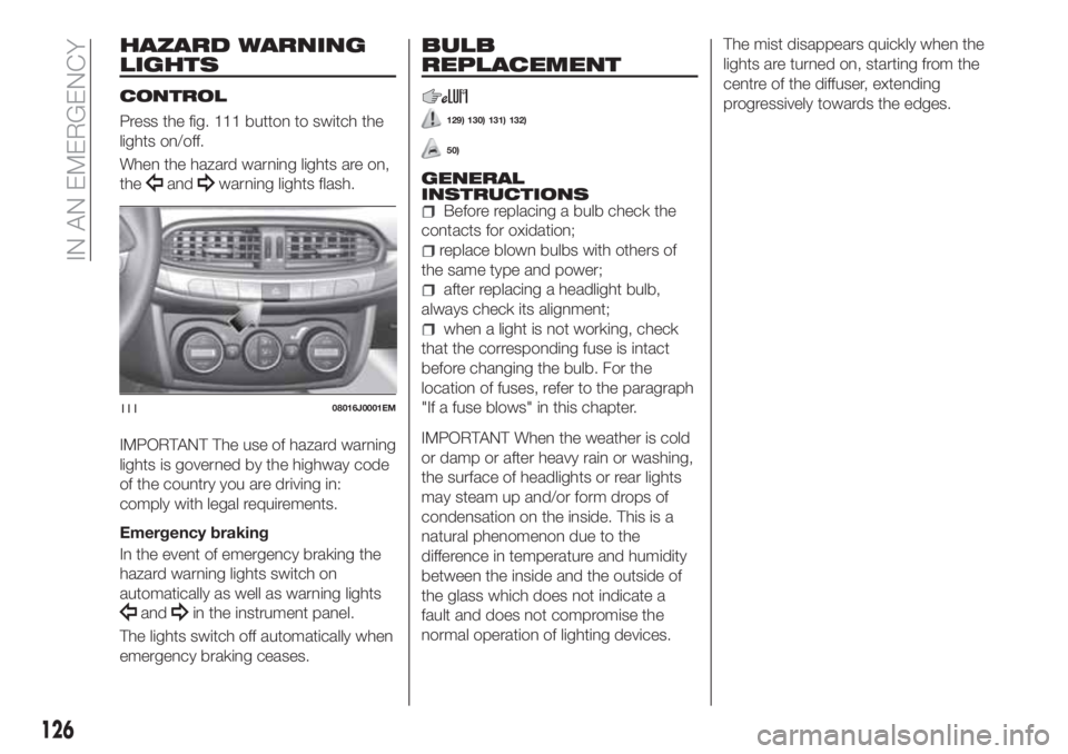
Press the fig. 111 button to switch the
lights on/off.
When the hazard warning lights are on,
the
andwarning lights flash.
IMPORTANT The use of hazard warning
lights is governed by the highway code
of the country you are driving in:
comply with legal requirements.
Emergency braking
In the event of emergency braking the
hazard warning lights switch on
automatically as well as warning lights
andin the instrument panel.
The lights switch off automatically when
emergency braking ceases.
BULB
REPLACEMENT
129) 130) 131) 132)
50)
GENERAL
INSTRUCTIONS
Before replacing a bulb check the
contacts for oxidation;
replace blown bulbs with others of
the same type and power;
after replacing a headlight bulb,
always check its alignment;
when a light is not working, check
that the corresponding fuse is intact
before changing the bulb. For the
location of fuses, refer to the paragraph
"If a fuse blows" in this chapter.
IMPORTANT When the weather is cold
or damp or after heavy rain or washing,
the surface of headlights or rear lights
may steam up and/or form drops of
condensation on the inside. This is a
natural phenomenon due to the
difference in temperature and humidity
between the inside and the outside of
the glass which does not indicate a
fault and does not compromise the
normal operation of lighting devices.The mist disappears quickly when the
lights are turned on, starting from the
centre of the diffuser, extending
progressively towards the edges.
11108016J0001EM
126
IN AN EMERGENCY
Page 137 of 252
DASHBOARD FUSE BOX
Left-hand drive version
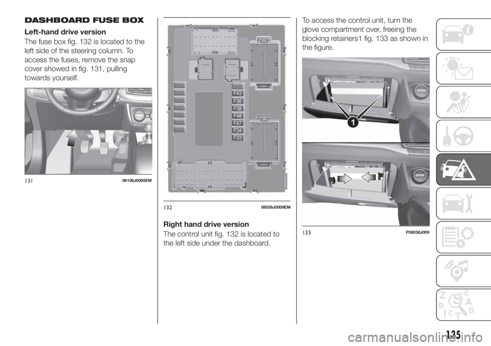
The fuse box fig. 132 is located to the
left side of the steering column. To
access the fuses, remove the snap
cover showed in fig. 131, pulling
towards yourself.
Right hand drive version
The control unit fig. 132 is located to
the left side under the dashboard.To access the control unit, turn the
glove compartment over, freeing the
blocking retainers1 fig. 133 as shown in
the figure.
13106106J0005EM
13208036J0009EM
133P08036J009
135
Page 142 of 252
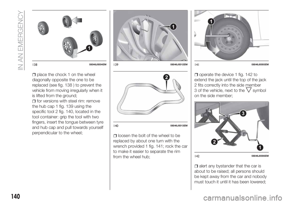
place the chock 1 on the wheel
diagonally opposite the one to be
replaced (see fig. 138 ) to prevent the
vehicle from moving irregularly when it
is lifted from the ground;
for versions with steel rim: remove
the hub cap 1 fig. 139 using the
specific tool 2 fig. 140, located in the
tool container: grip the tool with two
fingers, insert the tongue between tyre
and hub cap and pull towards yourself
perpendicular to the wheel;
loosen the bolt of the wheel to be
replaced by about one turn with the
wrench provided 1 fig. 141; rock the car
to make it easier to separate the rim
from the wheel hub;
operate the device 1 fig. 142 to
extend the jack until the top of the jack
2 fits correctly into the side member
3 of the vehicle, next to the
symbol
on the side member;
alert any bystander that the car is
about to be raised; all persons should
be kept away from the car and nobody
must touch it until it has been lowered;
13808046J0004EM13908046J0012EM
14008046J0013EM
14108046J0005EM
14208046J0006EM
140
IN AN EMERGENCY
Page 143 of 252
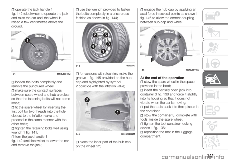
operate the jack handle 1
fig. 142 (clockwise) to operate the jack
and raise the car until the wheel is
raised a few centimetres above the
ground.
loosen the bolts completely and
remove the punctured wheel;
make sure the contact surfaces
between spare wheel and hub are clean
so that the fastening bolts will not come
loose;
fit the spare wheel by inserting the
first bolt for two threads into the hole
closest to the inflation valve and
proceed in the same manner with the
other bolts;
tighten the retaining bolts well using
wrench 1 fig. 141;
turn the jack handle 1
fig. 142 (anticlockwise) to lower the car
and remove the jack;
use the wrench provided to fasten
the bolts completely in a criss-cross
fashion as shown in fig. 144;
for versions with steel rim: make the
groove 1 fig. 145 provided on the hub
cap and highlighted by symbol
2 coincide with the inflation valve;
place the inner part of the hub cap
on the wheel rim;
engage the hub cap by applying an
axial force in several points as shown in
fig. 146 to allow the correct coupling
between hub cap and wheel.
At the end of the operation
stow the spare wheel in the space
provided in the boot;
insert the partially open jack into
container 3 fig. 136 and force it slightly
into its housing so that it does not
vibrate when the car is moving;
put the tools back into their places in
the container;
stow the container 3, complete with
tools, inside the spare wheel;
tighten the tool container locking
device 1 fig. 136;
reposition the mat in the luggage
compartment.
14308046J0001EM
144F1B0225C
14508046J0010EM
14608046J0011EM
141
Page 154 of 252
TOWING THE
VEHICLE
ATTACHING THE TOW
RING
150) 151) 152)
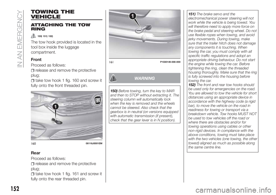
The tow hook provided is located in the
tool box inside the luggage
compartment.
Front
Proceed as follows:
release and remove the protective
plug;
take tow hook 1 fig. 160 and screw it
fully onto the front threaded pin.
Rear
Proceed as follows:
release and remove the protective
plug;
take tow hook 1 fig. 161 and screw it
fully onto the rear threaded pin.
WARNING
150)Before towing, turn the key to MAR
and then to STOP without extracting it. The
steering column will automatically lock
when the key is removed and the wheels
cannot be steered. Also check that the
gearbox is in neutral (on versions equipped
with automatic transmission (if present),
check that the gear lever is in N position).151)The brake servo and the
electromechanical power steering will not
work while the vehicle is being towed. You
will therefore need to apply more force on
the brake pedal and steering wheel. Do not
use flexible ropes when towing, and avoid
jerky movements. During towing, make
sure that the trailer hitch does not damage
any components it is touching. When
towing the car, you must comply with all
specific traffic regulations and adopt an
appropriate driving behaviour. Do not start
the engine while towing the car. Before
tightening the ring, clean the threaded
housing thoroughly. Make sure that the ring
is fully screwed into the housing before
towing the car.
152)The front and rear tow hooks should
be used only for emergencies on the road.
You are allowed to tow the vehicle for short
distances using an appropriate device in
accordance with the highway code (a rigid
bar), to move the vehicle on the road in
readiness for towing or transport via a
breakdown vehicle. Tow hooks MUST NOT
be used to tow vehicles off the road or
where there are obstacles and/or for
towing operations using cables or other
non-rigid devices. In compliance with the
above conditions, towing must take place
with the two vehicles (one towing, the other
towed) aligned as much as possible along
the same centre line.
16008116J0001EM
161P1030149-000-000
152
IN AN EMERGENCY
Page 156 of 252
SCHEDULED
SERVICING
Correct servicing is crucial for
guaranteeing a long life for the vehicle
under the best conditions.
For this reason, Fiat has planned a
series of checks and services at fixed
distance and/or time intervals, as
described in the Service Schedule.
To keep the car’s efficiency in tip-top
condition, in the following Scheduled
Service plan pages a few additional
checks are listed that should be carried
out more frequently with respect to the
normal coupon redemption schedule.
Scheduled Servicing is offered by all
Fiat Dealerships according to fixed time
or kilometres/miles intervals. If, during
each operation, in addition to the ones
scheduled, the need arises for further
replacements or repairs, these may be
carried out with the owner's explicit
agreement only. If your car is used
frequently for towing, the interval
between one scheduled servicing
operation and the next should be
reduced.
IMPORTANT NOTES
Scheduled Servicing interventions are
set out by the Manufacturer. Failure to
comply with the schedule may
invalidate the warranty.We advise sharing any doubts
regarding the proper operation of the
car with your Fiat Dealership, before
waiting for the next coupon redemption.
154
SERVICING AND CARE
Page 200 of 252
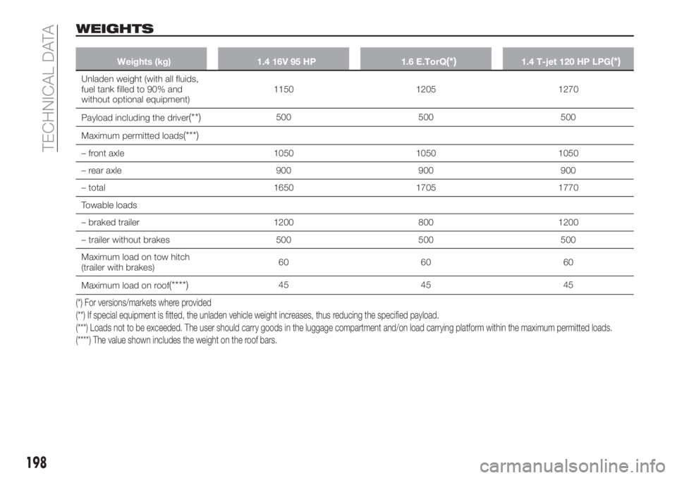
WEIGHTS
Weights (kg) 1.4 16V 95 HP 1.6 E.TorQ(*)1.4 T-jet 120 HP LPG(*)
Unladen weight (with all fluids,
fuel tank filled to 90% and
without optional equipment)1150 1205 1270
Payload including the driver
(**)500 500 500
Maximum permitted loads
(***)
– front axle 1050 1050 1050
– rear axle 900 900 900
– total 1650 1705 1770
Towable loads
– braked trailer 1200 800 1200
– trailer without brakes 500 500 500
Maximum load on tow hitch
(trailer with brakes)60 60 60
Maximum load on roof
(****)45 45 45
(*) For versions/markets where provided
(**) If special equipment is fitted, the unladen vehicle weight increases, thus reducing the specified payload.
(***) Loads not to be exceeded. The user should carry goods in the luggage compartment and/on load carrying platform within the maximum permitted loads.
(****) The value shown includes the weight on the roof bars.
198
TECHNICAL DATA
Page 201 of 252
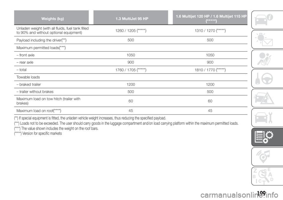
Weights (kg) 1.3 MultiJet 95 HP1.6 Multijet 120 HP / 1.6 Multijet 115 HP(*****)
Unladen weight (with all fluids, fuel tank filled
to 90% and without optional equipment)1260 / 1205(*****)1310 / 1270(*****)
Payload including the driver(**)500 500
Maximum permitted loads
(***)
– front axle 1050 1050
– rear axle 900 900
– total
1760 / 1705
(*****)1810 / 1770(*****)
Towable loads
– braked trailer 1200 1200
– trailer without brakes 500 500
Maximum load on tow hitch (trailer with
brakes)60 60
Maximum load on roof
(****)45 45
(*****) Version for specific markets (**) If special equipment is fitted, the unladen vehicle weight increases, thus reducing the specified payload.
(***) Loads not to be exceeded. The user should carry goods in the luggage compartment and/on load carrying platform within the maximum permitted loads.
(****) The value shown includes the weight on the roof bars.
199
Page 235 of 252
"Rear Park Assist vol."(where
provided): this function can be used to
select the volume of the acoustic
warnings provided by the rear Park
Assist system.
"Park Assist vol."(where provided):
this function can be used to select the
volume of the acoustic warnings
provided by the Park Assist system.
"Lane Assist Warning"(where
provided): this function can be used to
select the LaneAssist system
intervention "readiness".
"Lane Assist Strength"(where
provided): this function can be used to
select the force to apply to the steering
wheel to put the vehicle back in the
lane through the electric steering
system, in the event of Lane Assist
system intervention.
"Blind Spot Alert"(where provided):
this function can be used to select the
type of warning ("Sound Only" or
"Sound & Display") to indicate the
presence of objects in the blind spot of
the door mirror.
"Rain sensor"(where provided): this
function can be used to activate/
deactivate the automatic operation of
the wipers in the event of rain.
"Brakes"(where provided): this
function can be used to select the
following submenus:- "Brake Service" (where provided):
allows you to activate the procedure for
carrying out braking system servicing;
- "Auto Park Brake" (where provided):
allows you to activate/deactivate the
automatic park brake engagement.
NAVIGATION(only UConnect™ 5” Nav)
Planning a route
WARNING In the interest of safety and
to reduce distractions while you are
driving, you should always plan a route
before you start driving.
Using the destination search function, it
is possible to find and reach your
destinations in different ways: searching
for a specific address, a partial address,
a specific type of location (for example
a service station or a restaurant), a
postal code, a POI (Point Of Interest)
near your current position (for example,
a restaurant with the search type set to
"nearby"), a pair of latitude and
longitude coordinates, or by selecting a
point on the map.
Select “Search” in the Main menu and
set the search for a destination.
While entering the information, the list
displays the corresponding addresses
and POIs in two separate lists.The corresponding address and city are
displayed in the Address list and the
POI, the type of POIs and the locations
are displayed in the Point of Interest
lists.
To plan a route towards the destination,
select the “Guide” button.
A route is planned and you are guided
to your destination, using spoken
instructions and on-screen directions.
Map update
To ensure optimal performance, the
navigation system must be updated
periodically. For this, the Mopar Map
Care service offers a new map update
every three months.
The updates can be downloaded from
the maps.mopar.eu website and
installed directly on the navigator in your
car. All updates are free of charge for
3 years from the start of the warranty
on the car.
The navigation system can also be
updated at the Fiat Dealership.
NOTE The dealer may charge for
updating the navigation system.
VOICE COMMANDS
NoteFor languages not supported by
the system, voice commands are not
available.
233
Page 249 of 252
Side direction indicators (bulb
replacement)..............130
Snow chains...............181
Speed limiter...............111
SRS (supplementary restraint
system)..................97
Starting the engine...........104
Steering lock................11
Steering wheel...............18
Stop/Start system............109
Suggestions for driving.........118
Symbols....................3
TC (system)................70
Technical data..............187
Third brake light (bulb
replacement)..............132
Towing the vehicle............152
Towing trailers..............117Trip Computer...............49
TSC (system)................71
Tyres (inflation pressure)........195
Uconnect™ 5" - Uconnect™ 5"
Nav ...................224
Uconnect™ 5” LIVE —
Uconnect™ 5” Nav LIVE
Bluetooth® source.........229
Controls on the front panel. . . .224
Controls on the steering wheel . .226
Settings................232
System on/off.............220
USB source..............230
Uconnect™ Radio............214
Controls on front panel.......214
Controls on the steering wheel . .217
Phone mode.............222Radio mode..............220
USB source..............221
Use of the Owner Handbook.......4Vehicle changes/alterations.......3
Version with LPG system........36
Warning lights and messages.....51
Weights..................198
Wheels...................192
Wheels and tyres.............181
Window bag...............101
Windows (cleaning)...........183
Windscreen wiper
replacing blades...........178
Xenon gas discharge main
beam/dipped beam headlights
(bulb replacement)..........131