FORD E SERIES 2005 4.G Owners Manual
Manufacturer: FORD, Model Year: 2005, Model line: E SERIES, Model: FORD E SERIES 2005 4.GPages: 248, PDF Size: 5.53 MB
Page 171 of 248
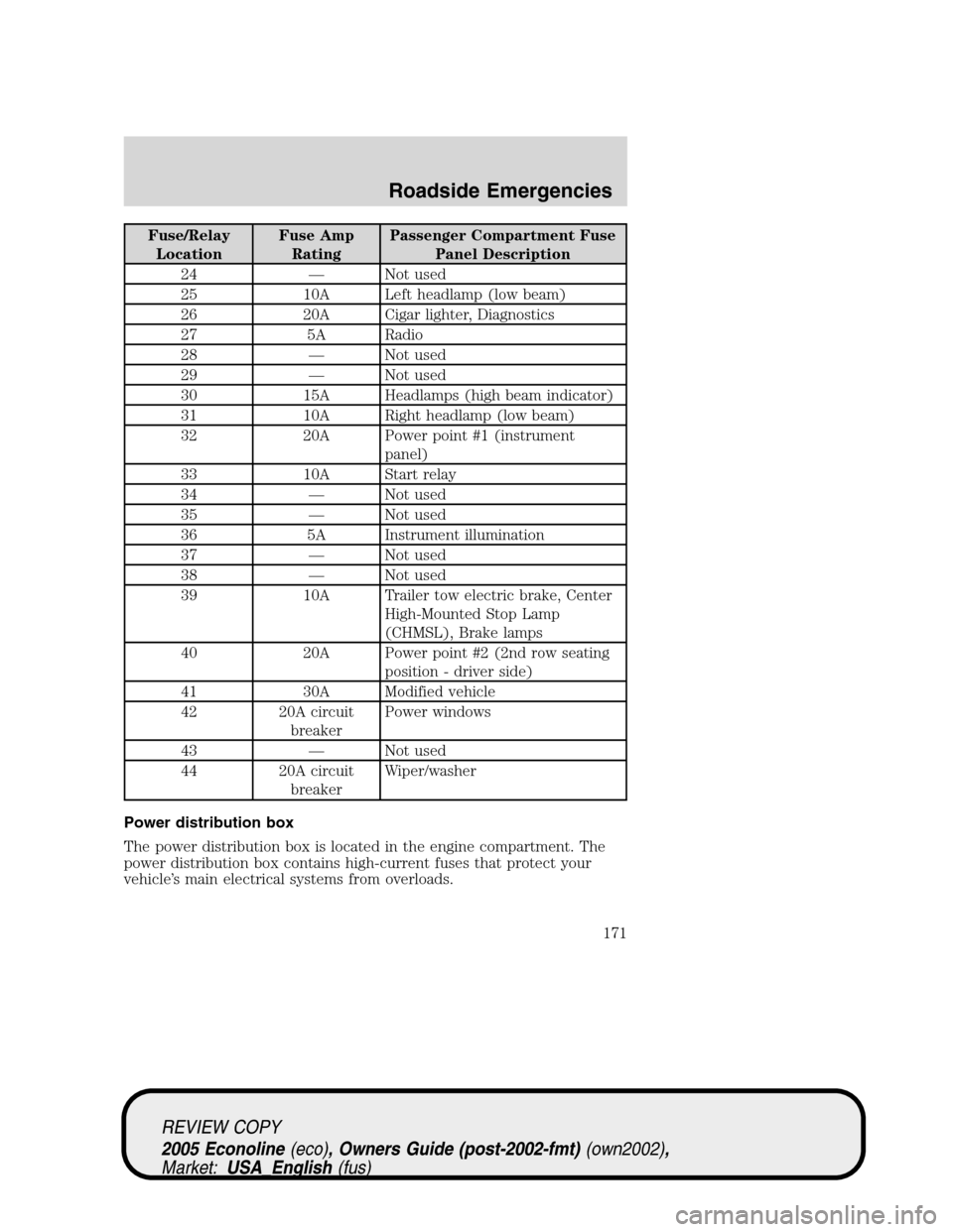
Fuse/Relay
LocationFuse Amp
RatingPassenger Compartment Fuse
Panel Description
24 — Not used
25 10A Left headlamp (low beam)
26 20A Cigar lighter, Diagnostics
27 5A Radio
28 — Not used
29 — Not used
30 15A Headlamps (high beam indicator)
31 10A Right headlamp (low beam)
32 20A Power point #1 (instrument
panel)
33 10A Start relay
34 — Not used
35 — Not used
36 5A Instrument illumination
37 — Not used
38 — Not used
39 10A Trailer tow electric brake, Center
High-Mounted Stop Lamp
(CHMSL), Brake lamps
40 20A Power point #2 (2nd row seating
position - driver side)
41 30A Modified vehicle
42 20A circuit
breakerPower windows
43 — Not used
44 20A circuit
breakerWiper/washer
Power distribution box
The power distribution box is located in the engine compartment. The
power distribution box contains high-current fuses that protect your
vehicle’s main electrical systems from overloads.
REVIEW COPY
2005 Econoline(eco), Owners Guide (post-2002-fmt)(own2002),
Market:USA_English(fus)
Roadside Emergencies
171
Page 172 of 248
Always disconnect the battery before servicing high current
fuses.
Always replace the cover to the power distribution box before
reconnecting the battery or refilling fluid reservoirs.
If the battery has been disconnected and reconnected, refer to the
Batterysection of theMaintenance and Specificationschapter.
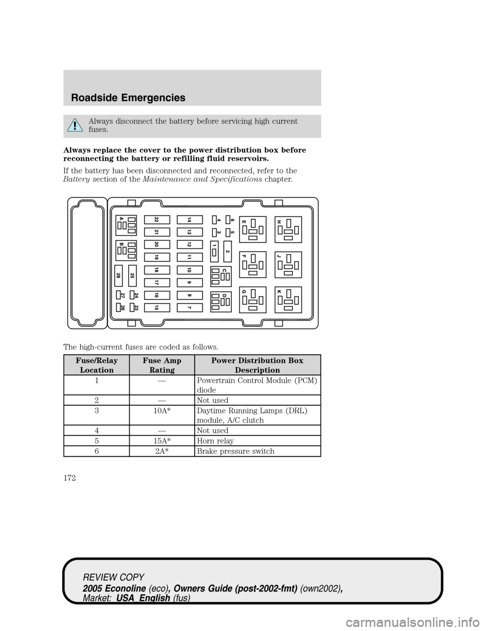
The high-current fuses are coded as follows.
Fuse/Relay
LocationFuse Amp
RatingPower Distribution Box
Description
1 — Powertrain Control Module (PCM)
diode
2 — Not used
3 10A* Daytime Running Lamps (DRL)
module, A/C clutch
4 — Not used
5 15A* Horn relay
6 2A* Brake pressure switch
REVIEW COPY
2005 Econoline(eco), Owners Guide (post-2002-fmt)(own2002),
Market:USA_English(fus)
Roadside Emergencies
172
Page 173 of 248
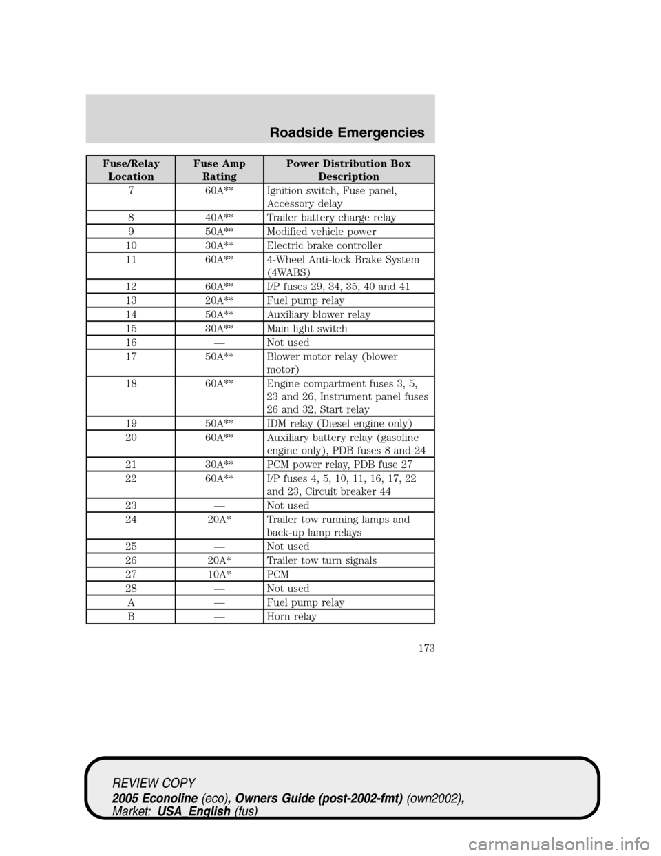
Fuse/Relay
LocationFuse Amp
RatingPower Distribution Box
Description
7 60A** Ignition switch, Fuse panel,
Accessory delay
8 40A** Trailer battery charge relay
9 50A** Modified vehicle power
10 30A** Electric brake controller
11 60A** 4-Wheel Anti-lock Brake System
(4WABS)
12 60A** I/P fuses 29, 34, 35, 40 and 41
13 20A** Fuel pump relay
14 50A** Auxiliary blower relay
15 30A** Main light switch
16 — Not used
17 50A** Blower motor relay (blower
motor)
18 60A** Engine compartment fuses 3, 5,
23 and 26, Instrument panel fuses
26 and 32, Start relay
19 50A** IDM relay (Diesel engine only)
20 60A** Auxiliary battery relay (gasoline
engine only), PDB fuses 8 and 24
21 30A** PCM power relay, PDB fuse 27
22 60A** I/P fuses 4, 5, 10, 11, 16, 17, 22
and 23, Circuit breaker 44
23 — Not used
24 20A* Trailer tow running lamps and
back-up lamp relays
25 — Not used
26 20A* Trailer tow turn signals
27 10A* PCM
28 — Not used
A — Fuel pump relay
B — Horn relay
REVIEW COPY
2005 Econoline(eco), Owners Guide (post-2002-fmt)(own2002),
Market:USA_English(fus)
Roadside Emergencies
173
Page 174 of 248
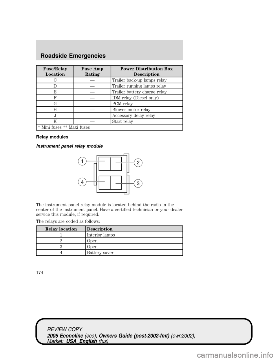
Fuse/Relay
LocationFuse Amp
RatingPower Distribution Box
Description
C — Trailer back-up lamps relay
D — Trailer running lamps relay
E — Trailer battery charge relay
F — IDM relay (Diesel only)
G — PCM relay
H — Blower motor relay
J — Accessory delay relay
K — Start relay
* Mini fuses ** Maxi fuses
Relay modules
Instrument panel relay module
The instrument panel relay module is located behind the radio in the
center of the instrument panel. Have a certified technician or your dealer
service this module, if required.
The relays are coded as follows:
Relay location Description
1 Interior lamps
2 Open
3 Open
4 Battery saver
REVIEW COPY
2005 Econoline(eco), Owners Guide (post-2002-fmt)(own2002),
Market:USA_English(fus)
Roadside Emergencies
174
Page 175 of 248
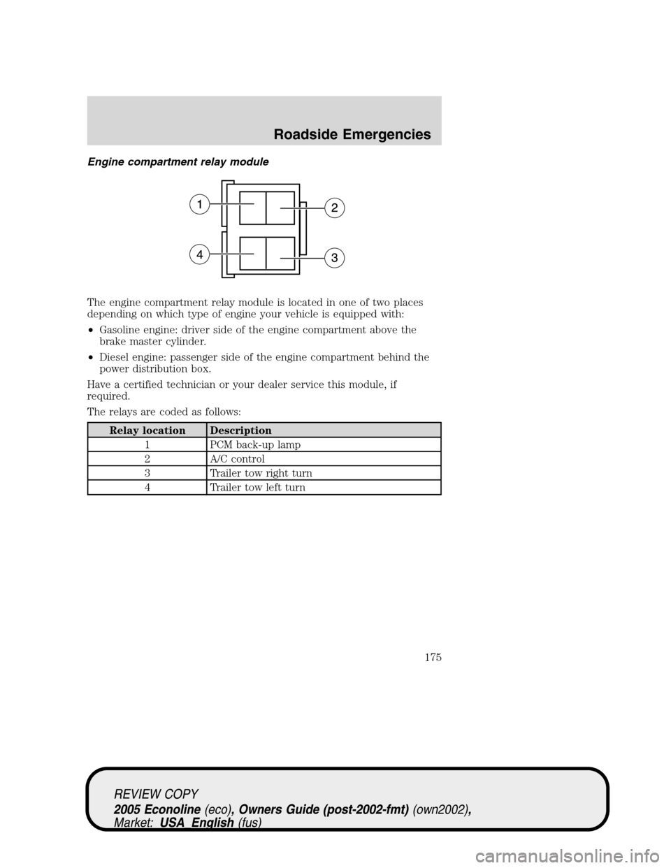
Engine compartment relay module
The engine compartment relay module is located in one of two places
depending on which type of engine your vehicle is equipped with:
•Gasoline engine: driver side of the engine compartment above the
brake master cylinder.
•Diesel engine: passenger side of the engine compartment behind the
power distribution box.
Have a certified technician or your dealer service this module, if
required.
The relays are coded as follows:
Relay location Description
1 PCM back-up lamp
2 A/C control
3 Trailer tow right turn
4 Trailer tow left turn
REVIEW COPY
2005 Econoline(eco), Owners Guide (post-2002-fmt)(own2002),
Market:USA_English(fus)
Roadside Emergencies
175
Page 176 of 248
JUMP STARTING YOUR VEHICLE
The following procedure is for vehicles equipped with a gasoline engine;
if your vehicle is equipped with a diesel engine, refer to the6.0L Power
Stroke Direct Injection Turbo Diesel Owner’s Guide Supplementfor
the proper jump starting procedure.
The gases around the battery can explode if exposed to flames,
sparks, or lit cigarettes. An explosion could result in injury or
vehicle damage.
Batteries contain sulfuric acid which can burn skin, eyes and
clothing, if contacted.
Do not attempt to push-start your vehicle. Automatic
transmissions do not have push-start capability; doing so may
damage the catalytic converter.
Preparing your vehicle
When the battery is disconnected or a new battery is installed, the
transmission must relearn its shift strategy. As a result, the transmission
may have firm and/or soft shifts. This operation is considered normal and
will not affect function or durability of the transmission. Over time, the
adaptive learning process will fully update transmission operation.
1.Use only a 12–volt supply to start your vehicle.
2. Do not disconnect the battery of the disabled vehicle as this could
damage the vehicle’s electrical system.
3. Park the booster vehicle close to the hood of the disabled vehicle
making sure the two vehiclesdo nottouch. Set the parking brake on
both vehicles and stay clear of the engine cooling fan and other moving
parts.
4. Check all battery terminals and remove any excessive corrosion before
you attach the battery cables. Ensure that vent caps are tight and level.
5. Turn the heater fan on in both vehicles to protect any electrical
surges. Turn all other accessories off.
REVIEW COPY
2005 Econoline(eco), Owners Guide (post-2002-fmt)(own2002),
Market:USA_English(fus)
Roadside Emergencies
176
Page 177 of 248
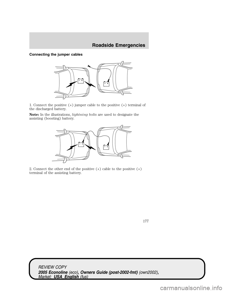
Connecting the jumper cables
1. Connect the positive (+) jumper cable to the positive (+) terminal of
the discharged battery.
Note:In the illustrations,lightning boltsare used to designate the
assisting (boosting) battery.
2. Connect the other end of the positive (+) cable to the positive (+)
terminal of the assisting battery.
+–+–
+–+–
REVIEW COPY
2005 Econoline(eco), Owners Guide (post-2002-fmt)(own2002),
Market:USA_English(fus)
Roadside Emergencies
177
Page 178 of 248
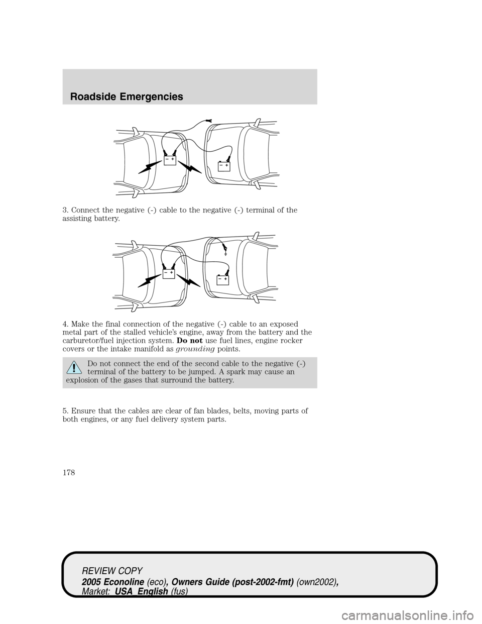
3. Connect the negative (-) cable to the negative (-) terminal of the
assisting battery.
4. Make the final connection of the negative (-) cable to an exposed
metal part of the stalled vehicle’s engine, away from the battery and the
carburetor/fuel injection system.Do notuse fuel lines, engine rocker
covers or the intake manifold asgroundingpoints.
Do not connect the end of the second cable to the negative (-)
terminal of the battery to be jumped. A spark may cause an
explosion of the gases that surround the battery.
5. Ensure that the cables are clear of fan blades, belts, moving parts of
both engines, or any fuel delivery system parts.
+–+–
+–+–
REVIEW COPY
2005 Econoline(eco), Owners Guide (post-2002-fmt)(own2002),
Market:USA_English(fus)
Roadside Emergencies
178
Page 179 of 248
Jump starting
1. Start the engine of the booster vehicle and run the engine at
moderately increased speed.
2. Start the engine of the disabled vehicle.
3. Once the disabled vehicle has been started, run both engines for an
additional three minutes before disconnecting the jumper cables.
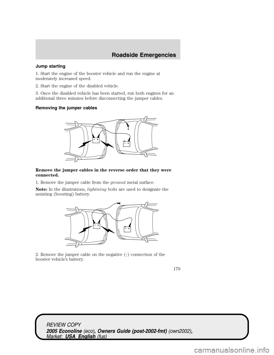
Removing the jumper cables
Remove the jumper cables in the reverse order that they were
connected.
1. Remove the jumper cable from thegroundmetal surface.
Note:In the illustrations,lightning boltsare used to designate the
assisting (boosting) battery.
2. Remove the jumper cable on the negative (-) connection of the
booster vehicle’s battery.
+–+–
+–+–
REVIEW COPY
2005 Econoline(eco), Owners Guide (post-2002-fmt)(own2002),
Market:USA_English(fus)
Roadside Emergencies
179
Page 180 of 248
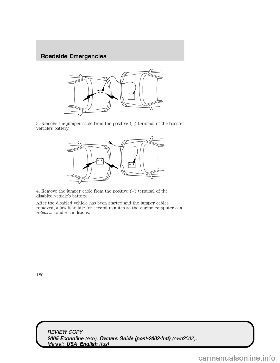
3. Remove the jumper cable from the positive (+) terminal of the booster
vehicle’s battery.
4. Remove the jumper cable from the positive (+) terminal of the
disabled vehicle’s battery.
After the disabled vehicle has been started and the jumper cables
removed, allow it to idle for several minutes so the engine computer can
relearnits idle conditions.
+–+–
+–+–
REVIEW COPY
2005 Econoline(eco), Owners Guide (post-2002-fmt)(own2002),
Market:USA_English(fus)
Roadside Emergencies
180