clutch FORD ESCAPE 2003 1.G Owners Manual
[x] Cancel search | Manufacturer: FORD, Model Year: 2003, Model line: ESCAPE, Model: FORD ESCAPE 2003 1.GPages: 240, PDF Size: 2.6 MB
Page 51 of 240
Increasing speed while using speed control
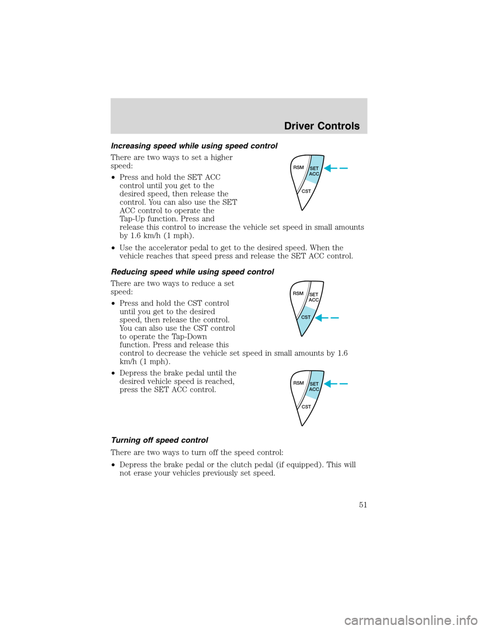
There are two ways to set a higher
speed:
•Press and hold the SET ACC
control until you get to the
desired speed, then release the
control. You can also use the SET
ACC control to operate the
Tap-Up function. Press and
release this control to increase the vehicle set speed in small amounts
by 1.6 km/h (1 mph).
•Use the accelerator pedal to get to the desired speed. When the
vehicle reaches that speed press and release the SET ACC control.
Reducing speed while using speed control
There are two ways to reduce a set
speed:
•Press and hold the CST control
until you get to the desired
speed, then release the control.
You can also use the CST control
to operate the Tap-Down
function. Press and release this
control to decrease the vehicle set speed in small amounts by 1.6
km/h (1 mph).
•Depress the brake pedal until the
desired vehicle speed is reached,
press the SET ACC control.
Turning off speed control
There are two ways to turn off the speed control:
•Depress the brake pedal or the clutch pedal (if equipped). This will
not erase your vehicles previously set speed.
RSM
SET
ACC
CST
RSM
SET
ACC
CST
RSM
SET
ACC
CST
Driver Controls
51
Page 116 of 240
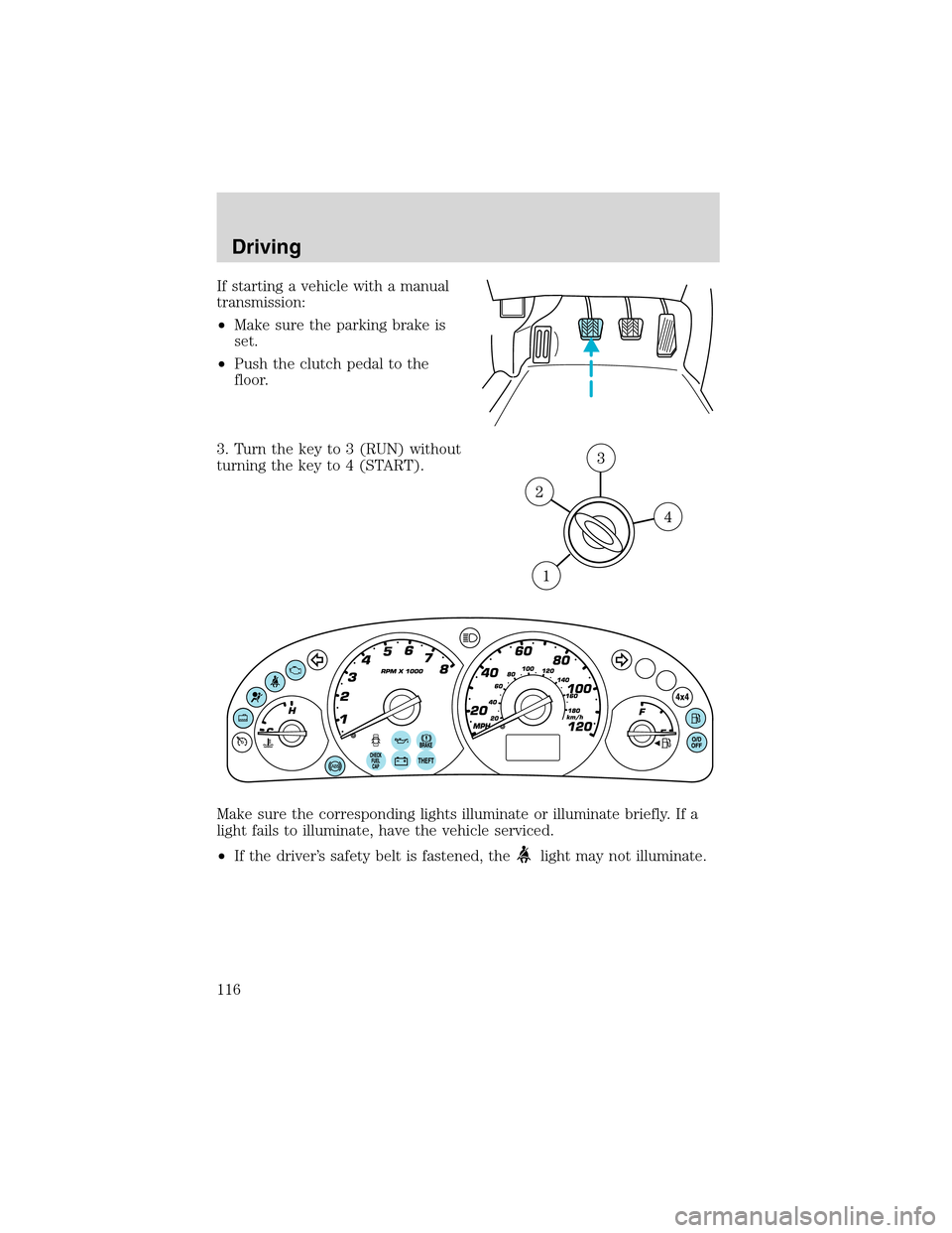
If starting a vehicle with a manual
transmission:
•Make sure the parking brake is
set.
•Push the clutch pedal to the
floor.
3. Turn the key to 3 (RUN) without
turning the key to 4 (START).
Make sure the corresponding lights illuminate or illuminate briefly. If a
light fails to illuminate, have the vehicle serviced.
•If the driver’s safety belt is fastened, the
light may not illuminate.
Driving
116
Page 125 of 240
Do not rock the vehicle for more than a minute or damage to the
transmission and tires may occur, or the engine may overheat.
MANUAL TRANSAXLE OPERATION (IF EQUIPPED)
USING THE CLUTCH
Vehicles equipped with a manual transaxle have a starter interrupt
interlock that prevents cranking of the engine unless the clutch pedal is
depressed.
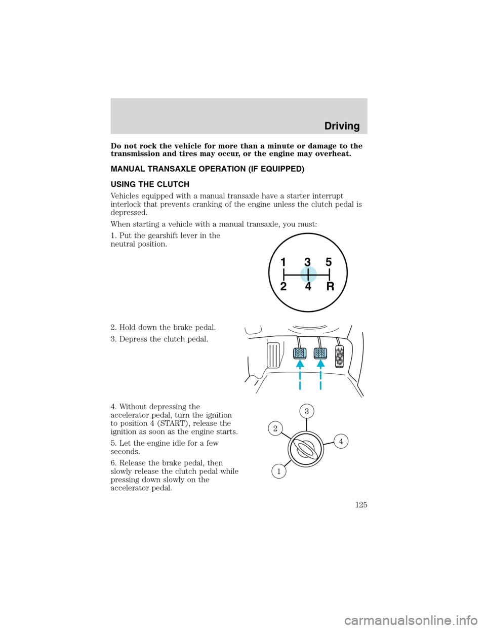
When starting a vehicle with a manual transaxle, you must:
1. Put the gearshift lever in the
neutral position.
2. Hold down the brake pedal.
3. Depress the clutch pedal.
4. Without depressing the
accelerator pedal, turn the ignition
to position 4 (START), release the
ignition as soon as the engine starts.
5. Let the engine idle for a few
seconds.
6. Release the brake pedal, then
slowly release the clutch pedal while
pressing down slowly on the
accelerator pedal.
1
24R35
Driving
125
Page 126 of 240
Do not drive with your foot resting on the clutch pedal and do
not use the clutch pedal to hold your vehicle at a standstill while
waiting on a hill. These actions will seriously reduce clutch life.
RECOMMENDED SHIFT SPEEDS
Upshift according to the following charts for best fuel economy:
Upshifts when accelerating (recommended for best fuel
economy)
1-2 22 km/h (14 mph)
2-3 40 km/h (25 mph)
3-4 55 km/h (34 mph)
4-5 70 km/h (44 mph)
Upshifts when cruising (recommended for best fuel economy)
1-2 19 km/h (12 mph)
2-3 31 km/h (19 mph)
3-4 46 km/h (29 mph)
4-5 61 km/h (38 mph)
REVERSE
Make sure that your vehicle is at a complete stop before you shift
into R (Reverse). Failure to do so may damage the transaxle.
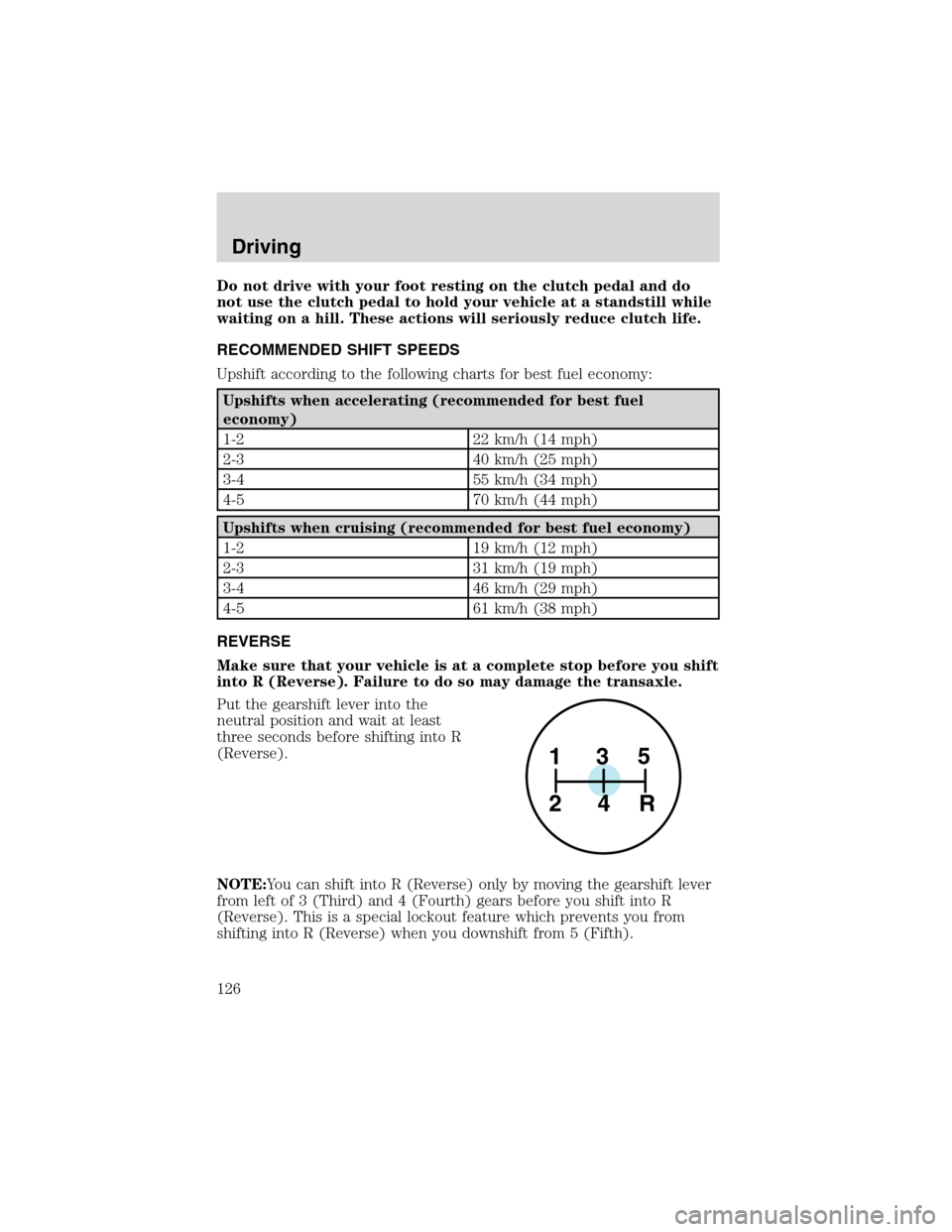
Put the gearshift lever into the
neutral position and wait at least
three seconds before shifting into R
(Reverse).
NOTE:You can shift into R (Reverse) only by moving the gearshift lever
from left of 3 (Third) and 4 (Fourth) gears before you shift into R
(Reverse). This is a special lockout feature which prevents you from
shifting into R (Reverse) when you downshift from 5 (Fifth).
1
24R35
Driving
126
Page 153 of 240
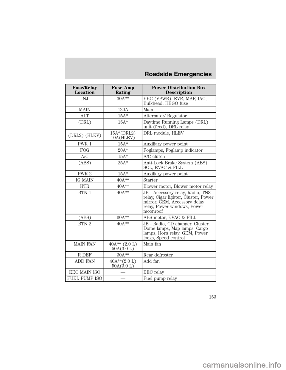
Fuse/Relay
LocationFuse Amp
RatingPower Distribution Box
Description
INJ 30A** EEC (VPWR), EVR, MAF, IAC,
Bulkhead, HEGO fuse
MAIN 120A Main
ALT 15A* Alternator/ Regulator
(DRL) 15A* Daytime Running Lamps (DRL)
unit (feed), DRL relay
(DRL2) (HLEV)15A*(DRL2)
10A(HLEV)DRL module, HLEV
PWR 1 15A* Auxiliary power point
FOG 20A* Foglamps, Foglamp indicator
A/C 15A* A/C clutch
(ABS) 25A* Anti-Lock Brake System (ABS)
SOL, EVAC & FILL
PWR 2 15A* Auxiliary power point
IG MAIN 40A** Starter
HTR 40A** Blower motor, Blower motor relay
BTN 1 40A** JB - Accessory relay, Radio, TNS
relay, Cigar lighter, Cluster, Power
mirror, GEM, Accessory delay
relay, Power windows, Power
moonroof
(ABS) 60A** ABS motor, EVAC & FILL
BTN 2 40A** JB - Radio, CD changer, Cluster,
Dome lamps, Map lamps, Cargo
lamps, Horn relay, GEM, Power
locks, Speed control
MAIN FAN 40A** (2.0 L)
50A(3.0 L)Main fan
R DEF 30A** Rear defroster
ADD FAN 40A**(2.0 L)
50A(3.0 L)Add fan
EEC MAIN ISO—EEC relay
FUEL PUMP ISO—Fuel pump relay
Roadside Emergencies
153
Page 154 of 240
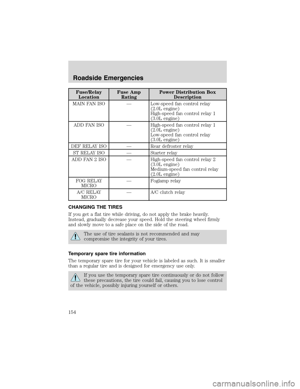
Fuse/Relay
LocationFuse Amp
RatingPower Distribution Box
Description
MAIN FAN ISO—Low-speed fan control relay
(2.0L engine)
High-speed fan control relay 1
(3.0L engine)
ADD FAN ISO—High-speed fan control relay 1
(2.0L engine)
Low-speed fan control relay
(3.0L engine)
DEF RELAY ISO—Rear defroster relay
ST RELAY ISO—Starter relay
ADD FAN 2 ISO—High-speed fan control relay 2
(3.0L engine)
Medium-speed fan control relay
(2.0L engine)
FOG RELAY
MICRO—Foglamp relay
A/C RELAY
MICRO—A/C clutch relay
CHANGING THE TIRES
If you get a flat tire while driving, do not apply the brake heavily.
Instead, gradually decrease your speed. Hold the steering wheel firmly
and slowly move to a safe place on the side of the road.
The use of tire sealants is not recommended and may
compromise the integrity of your tires.
Temporary spare tire information
The temporary spare tire for your vehicle is labeled as such. It is smaller
than a regular tire and is designed for emergency use only.
If you use the temporary spare tire continuously or do not follow
these precautions, the tire could fail, causing you to lose control
of the vehicle, possibly injuring yourself or others.
Roadside Emergencies
154
Page 183 of 240
SERVICE RECOMMENDATIONS
To help you service your vehicle:
•We highlight do-it-yourself items in the engine compartment for easy
location.
•We provide a scheduled maintenance guide which makes tracking
routine service easy.
If your vehicle requires professional service, your dealership can provide
the necessary parts and service. Check yourWarranty Guide/Owner
Information Guideto find out which parts and services are covered.
Use only recommended fuels, lubricants, fluids and service parts
conforming to specifications. Motorcraft parts are designed and built to
provide the best performance in your vehicle.
PRECAUTIONS WHEN SERVICING YOUR VEHICLE
•Do not work on a hot engine.
•Make sure that nothing gets caught in moving parts.
•Do not work on a vehicle with the engine running in an enclosed
space, unless you are sure you have enough ventilation.
•Keep all open flames and other lit material away from the battery and
all fuel related parts.
Working with the engine off
•Automatic transmission:
1. Set the parking brake and shift to P (Park).
2. Turn off the engine and remove the key.
3. Block the wheels.
•Manual transmission:
1. Set the parking brake, depress the clutch and place the gearshift in 1
(First).
2. Turn off the engine and remove the key.
3. Block the wheels.
Working with the engine on
•Automatic transmission:
1. Set the parking brake and shift to P (Park).
2. Block the wheels.
Maintenance and Specifications
183
Page 184 of 240
•Manual transmission:
1. Set the parking brake, depress the clutch and place the gearshift in N
(Neutral).
2. Block the wheels.
Note:Do not start your engine with the air cleaner removed and do not
remove it while the engine is running.
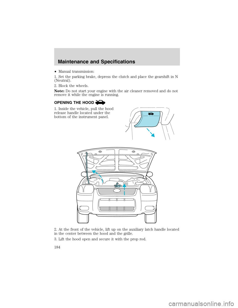
OPENING THE HOOD
1. Inside the vehicle, pull the hood
release handle located under the
bottom of the instrument panel.
2. At the front of the vehicle, lift up on the auxiliary latch handle located
in the center between the hood and the grille.
3. Lift the hood open and secure it with the prop rod.
Maintenance and Specifications
184
Page 185 of 240
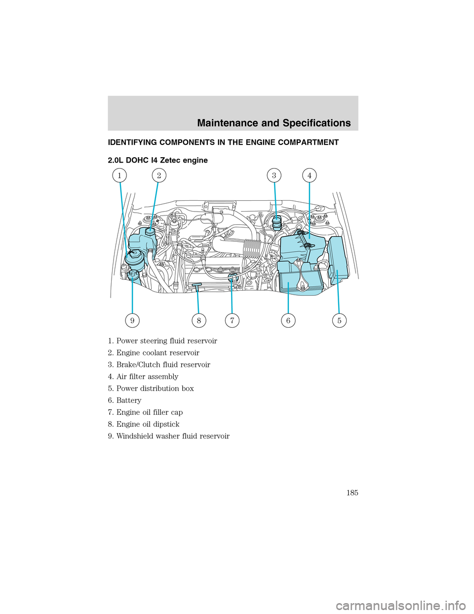
IDENTIFYING COMPONENTS IN THE ENGINE COMPARTMENT
2.0L DOHC I4 Zetec engine
1. Power steering fluid reservoir
2. Engine coolant reservoir
3. Brake/Clutch fluid reservoir
4. Air filter assembly
5. Power distribution box
6. Battery
7. Engine oil filler cap
8. Engine oil dipstick
9. Windshield washer fluid reservoir
5678
1234
9
Maintenance and Specifications
185
Page 209 of 240
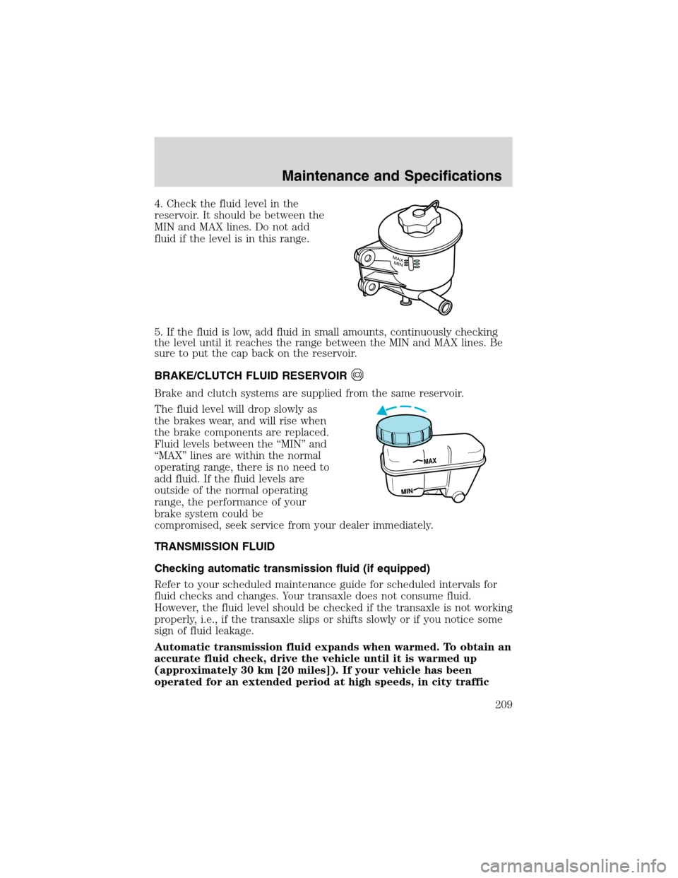
4. Check the fluid level in the
reservoir. It should be between the
MIN and MAX lines. Do not add
fluid if the level is in this range.
5. If the fluid is low, add fluid in small amounts, continuously checking
the level until it reaches the range between the MIN and MAX lines. Be
sure to put the cap back on the reservoir.
BRAKE/CLUTCH FLUID RESERVOIR
Brake and clutch systems are supplied from the same reservoir.
The fluid level will drop slowly as
the brakes wear, and will rise when
the brake components are replaced.
Fluid levels between the“MIN”and
“MAX”lines are within the normal
operating range, there is no need to
add fluid. If the fluid levels are
outside of the normal operating
range, the performance of your
brake system could be
compromised, seek service from your dealer immediately.
TRANSMISSION FLUID
Checking automatic transmission fluid (if equipped)
Refer to your scheduled maintenance guide for scheduled intervals for
fluid checks and changes. Your transaxle does not consume fluid.
However, the fluid level should be checked if the transaxle is not working
properly, i.e., if the transaxle slips or shifts slowly or if you notice some
sign of fluid leakage.
Automatic transmission fluid expands when warmed. To obtain an
accurate fluid check, drive the vehicle until it is warmed up
(approximately 30 km [20 miles]). If your vehicle has been
operated for an extended period at high speeds, in city traffic
MAXMIN
Maintenance and Specifications
209