fuse FORD F650/750 2019 Owners Manual
[x] Cancel search | Manufacturer: FORD, Model Year: 2019, Model line: F650/750, Model: FORD F650/750 2019Pages: 387, PDF Size: 4.78 MB
Page 6 of 387
Using Traction Control - Vehicles With:
Hydraulic Brakes ......................................133
Stability Control
Principle of Operation ................................
135
Using Stability Control ..............................
136
Cruise Control
Principle of Operation ................................
138
Using Cruise Control ...................................
138
Driving Aids
Steering ...........................................................
140
Load Carrying
Load Limit ........................................................
141
Air Suspension ..............................................
142
Towing
Towing a Trailer ............................................
144
Recommended Towing Weights ...........
145
Essential Towing Checks ..........................
146
Fifth Wheel Operation ...............................
147
Driving Hints
Breaking-In ....................................................
149
General Driving Points ...............................
149
Economical Driving .....................................
150
Cold Weather Precautions ........................
151
Driving Through Water ...............................
153
Roadside Emergencies
Roadside Assistance ..................................
154
Hazard Flashers ............................................
155
Fuel Shutoff ...................................................
155
Jump Starting the Vehicle ........................
156
Transporting the Vehicle ..........................
158
Customer Assistance
Ford Credit .....................................................
160Getting the Services You Need
..............
160
In California (U.S. Only) .............................
161
The Better Business Bureau (BBB) Auto Line Program (U.S. Only) .....................
162
Utilizing the Mediation/Arbitration Program (Canada Only) .......................
163
Getting Assistance Outside the U.S. and Canada ........................................................
163
Ordering Additional Owner's Literature ........................................................................\
.
164
Reporting Safety Defects (U.S. Only) ........................................................................\
.
165
Reporting Safety Defects (Canada Only) ........................................................................\
.
165
Fuses
Fuse Specification Chart ...........................
167
Changing a Fuse ...........................................
176
Vehicle Inspection Guide
Vehicle Inspection Information ..............
178
Maintenance
General Information ...................................
187
Opening and Closing the Hood .............
188
Under Hood Overview - 6.7L Diesel ......
190
Under Hood Overview - 6.8L ...................
191
Engine Oil Dipstick - 6.7L Diesel .............
192
Engine Oil Dipstick - 6.8L .........................
192
Engine Oil Check - 6.7L Diesel ................
192
Engine Oil Check - 6.8L .............................
193
Changing the Engine Oil and Oil Filter ........................................................................\
.
194
Changing the Crankcase Vent Filter Element - 6.7L Diesel .............................
195
Oil Change Indicator Reset ......................
196
Engine Coolant Check - 6.7L Diesel ......
196
Engine Coolant Check - 6.8L .................
200
Automatic Transmission Fluid Check ........................................................................\
204
Brake Fluid Check .......................................
205
3
F650750 (TBC) , enUSA, Edition date: 201804, Second-Printing Table of Contents
Page 13 of 387
•
The gearshift lever must be in P (Park)
or N (Neutral) in order for the starter
to operate.
• Try operating the starter switch several
times. This operation may clean
potentially corroded contacts or make
the switch temporarily operable until
you can reach the dealer.
• If all electrical connections are tight
and you need assistance to start, See
Jump Starting the Vehicle (page 156
).
If engine cranks but won ’t start
Prolonged starter cranking (in excess of 10
seconds) could cause damage to the
starter motor or the high-pressure fuel
pump.
• Check the fuel gauge. You may be out
of fuel. If the gauge shows that there
is fuel in the tank, the trouble may be
in the electrical system or the fuel
system. If equipped with an auxiliary
tank, be sure that the tank control
switch is set for the tank with fuel and
not on an empty tank.
• Leaving your ignition key turned to on
for over two minutes without starting
may make starting difficult because
the glow plugs will cease activation.
Reset the system by turning the ignition
key to off and then back to on again.
Note: If the system is out of fuel and the
engine will not start, do not continue
cranking the engine. Continued cranking can
damage the high-pressure fuel pump.
If the engine runs hot
The following could cause the engine to
overheat:
• Lack of coolant
• Dirty cooling system.
• Plugged radiator fins, A/C condenser
and/or oil cooler
• Malfunctioning fan drive •
Driving with frozen coolant
• Sticking thermostat
• Overloading or pulling heavy trailers
during hot weather
• Grill or radiator air blockage
• Slipping or missing drive belt
• Plugged or very dirty air filter
If fuses burn out WARNING:
Replacement fuses
and circuit breakers must always be the
same rating as the original equipment
shown. Never replace a fuse or circuit
breaker with one of a higher rating.
Higher rated fuses or circuit breakers
could allow circuit overloading in the
event of a circuit malfunction, resulting
in severe vehicle damage or personal
injury due to fire.
Burned-out or blown fuses usually indicate
an electrical short-circuit, although a fuse
may occasionally burn out from vibration.
Insert a second fuse. If this fuse
immediately burns out and you cannot
locate the cause, return your vehicle to
your dealer for a circuit check. See
Changing a Fuse
(page 176).
Selective catalytic reduction system
speed limit and Idle-only modes
If the vehicle ’s speed is limited or in an
idle-only mode, the selective catalytic
reduction system may be limiting the
vehicle ’s functions due to low or
contaminated DEF. Check the DEF. See
Selective Catalytic Reductant System
(page
105).
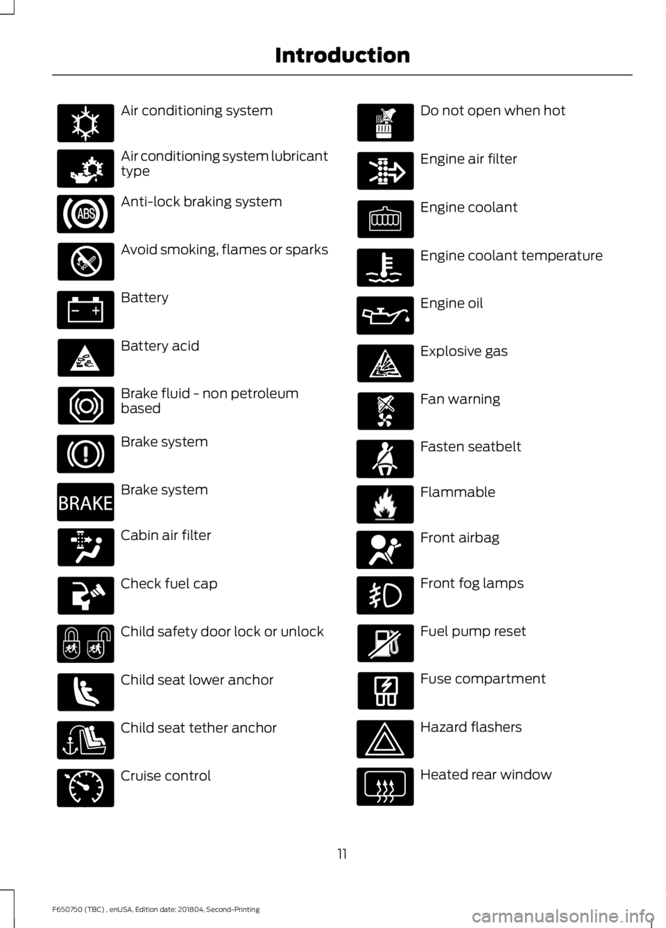
SYMBOLS GLOSSARY
These are some of the symbols you may
see on your vehicle.
10
F650750 (TBC) , enUSA, Edition date: 201804, Second-Printing Introduction
Page 14 of 387
Air conditioning system
Air conditioning system lubricant
type
Anti-lock braking system
Avoid smoking, flames or sparks
Battery
Battery acid
Brake fluid - non petroleum
based
Brake system
Brake system
Cabin air filter
Check fuel cap
Child safety door lock or unlock
Child seat lower anchor
Child seat tether anchor
Cruise control Do not open when hot
Engine air filter
Engine coolant
Engine coolant temperature
Engine oil
Explosive gas
Fan warning
Fasten seatbelt
Flammable
Front airbag
Front fog lamps
Fuel pump reset
Fuse compartment
Hazard flashers
Heated rear window
11
F650750 (TBC) , enUSA, Edition date: 201804, Second-Printing IntroductionE162384 E231157 E270480 E71340 E71880 E231160 E67017
Page 86 of 387
12 Volt DC Power Point
WARNING: Do not plug optional
electrical accessories into the cigar
lighter socket. Incorrect use of the cigar
lighter can cause damage not covered
by the vehicle warranty, and can result
in fire or serious injury.
Note: When you switch the ignition on, you
can use the socket to power 12 volt
appliances with a maximum current rating
of 15 amps.
If the power supply does not work after you
switch the ignition off, switch the ignition
on.
Note: Do not hang any accessory from the
accessory plug.
Note: Do not use the power point over the
vehicle capacity of 12 volt DC 180 watts or
a fuse may blow.
Note: Always keep the power point caps
closed when not in use.
Do not insert objects other than an
accessory plug into the power point. This
damages the power point and may blow
the fuse.
Run the vehicle for full capacity use of the
power point.
To prevent the battery from running out of
charge:
• Do not use the power point longer than
necessary when the vehicle is not
running.
• Do not leave devices plugged in
overnight or when you park your vehicle
for extended periods. Locations
Power points may be in the following
locations:
•
On the instrument panel (two
locations).
• Inside the front under-seat storage
compartment.
• Inside the rear under-seat storage
compartment.
110 Volt AC Power Point
(If Equipped) WARNING: Do not keep electrical
devices plugged in the power point
whenever the device is not in use. Do not
use any extension cord with the 110 volt
AC power point, since it will defeat the
safety protection design. Doing so may
cause the power point to overload due
to powering multiple devices that can
reach beyond the 150 watt load limit and
could result in fire or serious injury.
Note: The power point turns off when you
switch the ignition off, or when the battery
voltage drops below 11 volts.
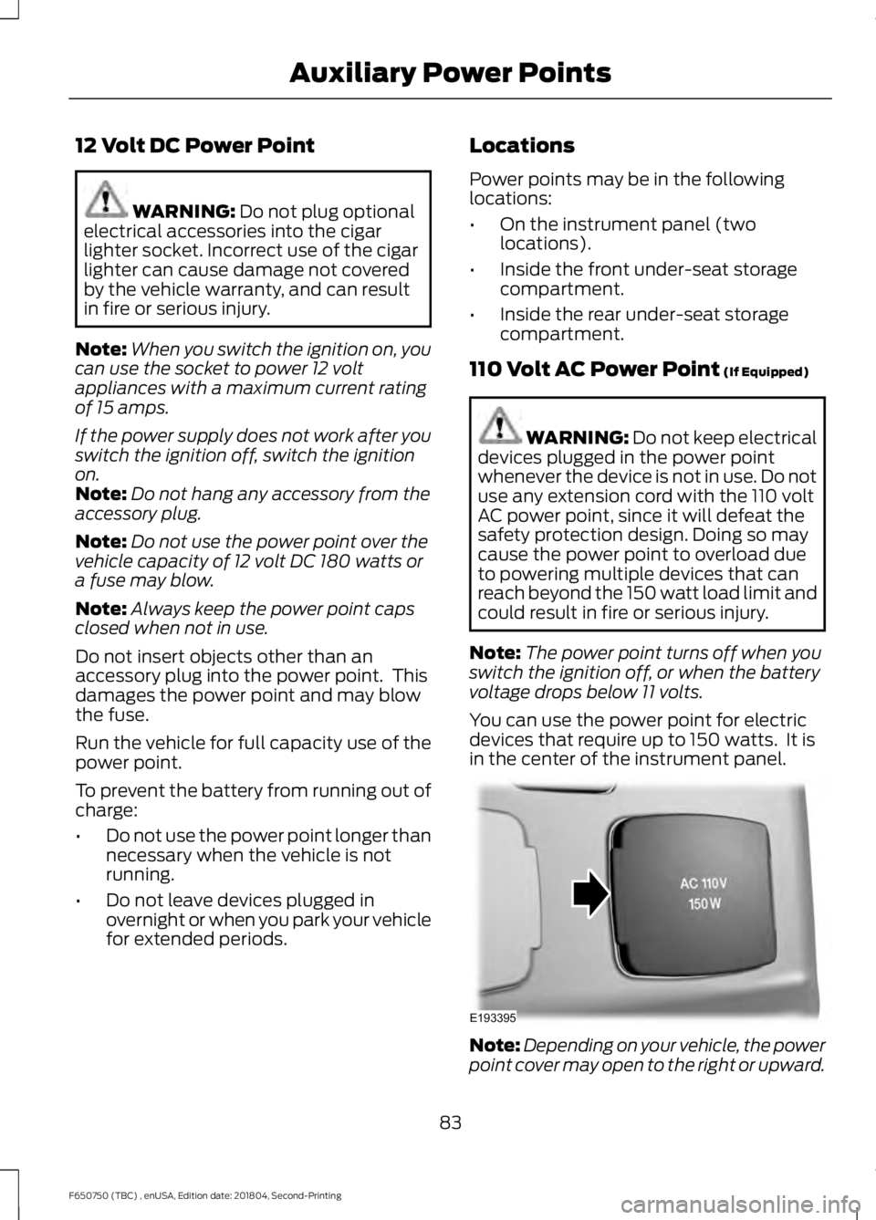
You can use the power point for electric
devices that require up to 150 watts. It is
in the center of the instrument panel. Note:
Depending on your vehicle, the power
point cover may open to the right or upward.
83
F650750 (TBC) , enUSA, Edition date: 201804, Second-Printing Auxiliary Power PointsE193395
Page 121 of 387
Automatic Transmission Adaptive
Learning
This feature's design is to increase
durability and provide consistent shift feel
over the life of your vehicle. A new vehicle
or transmission could have firm shifts, soft
shifts or both. This operation is normal and
does not affect function or durability of the
transmission. Over time, the adaptive
learning process fully updates transmission
operation. Additionally, whenever you
disconnect the battery or install a new
battery, the system must relearn the
strategy.
Brake-Shift Interlock
WARNING: Do not drive your
vehicle until you verify that the
stoplamps are working. WARNING:
When doing this
procedure, you need to take the
transmission out of park (P) which
means your vehicle can roll freely. To
avoid unwanted vehicle movement,
always fully apply the parking brake prior
to doing this procedure. Use wheels
chocks if appropriate. WARNING:
If the parking brake is
fully released, but the brake warning
lamp remains illuminated, the brakes
may not be working properly. Have your
vehicle checked as soon as possible.
Your vehicle is equipped with a brake-shift
interlock feature that prevents the
gearshift lever from moving from park (P)
when the ignition is in the 3 (on) position
and the brake pedal is not pressed. If you cannot move the gearshift lever out
of park (P) position with the ignition in the
4 (on) position and the brake pedal
pressed, a malfunction could have
occurred. It is possible that a fuse has
blown or your vehicle
’s brake lamps are
not operating properly.
See Fuse
Specification Chart (page 167).
If the fuse is not blown and the brake
lamps are working properly, the following
procedure allows you to move the gearshift
lever from park (P):
1. Apply the parking brake. Switch the ignition key to 1 (off), then remove the
key.
2. Move the steering column to the full down and full rearward position
(toward the driver ’s seat).
3. Remove the gearshift lever boot.
4. Place fingers into hole where you removed the gearshift lever boot and
pull top half of shroud up and forward
to separate it from the lower half of the
shroud. There is a hinge at the forward
edge of the top shroud. Roll the top
half of the shroud upward on the hinge
point to clear the hazard flasher button,
then pull straight rearward toward the
driver ’s seat to remove.
5. Remove the top half of the shroud.
6. Remove the three fasteners under the column that secure the lower shroud
half to the column.
118
F650750 (TBC) , enUSA, Edition date: 201804, Second-Printing Transmission
Page 147 of 387
TOWING A TRAILER
WARNING: Do not exceed
the GVWR or the GAWR
specified on the certification
label. WARNING:
Towing trailers
beyond the maximum
recommended gross trailer
weight exceeds the limit of the
vehicle and could result in engine
damage, transmission damage,
structural damage, loss of
vehicle control, vehicle rollover
and personal injury.
Your vehicle may have electrical
items, such as fuses or relays,
related to towing. See
Fuses
(page 167).
Your vehicle's load capacity
designation is by weight, not by
volume, so you cannot necessarily
use all available space when
loading a vehicle.
Towing a trailer places an extra
load on your vehicle's engine,
transmission, axle, brakes, tires
and suspension. Inspect these
components periodically during,
and after, any towing operation. Load Placement
To help minimize how trailer
movement affects your vehicle
when driving:
•
Load the heaviest items closest
to the trailer floor.
• Load the heaviest items
centered between the left and
right side trailer tires.
• Load the heaviest items above
the trailer axles or just slightly
forward toward the trailer
tongue. Do not allow the final
trailer tongue weight to go
above or below 10-15% of the
loaded trailer weight.
When driving with a trailer or
payload, a slight takeoff vibration
or shudder may be present due to
the increased payload weight.
Additional information regarding
proper trailer loading and setting
your vehicle up for towing is
located in another chapter of this
manual. See
Load Limit (page
141).
You can also find information in
the
RV & Trailer Towing Guide
available at your authorized
dealer, or online. RV & Trailer Towing Guide Online
http://www.fleet.ford.com/towing-guides/
Website
144
F650750 (TBC) , enUSA, Edition date: 201804, Second-Printing Towing
Page 159 of 387
JUMP STARTING THE VEHICLE
WARNING: Batteries normally
produce explosive gases which can
cause personal injury. Therefore, do not
allow flames, sparks or lighted
substances to come near the battery.
When working near the battery, always
shield your face and protect your eyes.
Always provide correct ventilation. WARNING:
Keep batteries out of
reach of children. Batteries contain
sulfuric acid. Avoid contact with skin,
eyes or clothing. Shield your eyes when
working near the battery to protect
against possible splashing of acid
solution. In case of acid contact with skin
or eyes, flush immediately with water for
a minimum of 15 minutes and get prompt
medical attention. If acid is swallowed,
call a physician immediately. WARNING:
Use only adequately
sized cables with insulated clamps.
Preparing Your Vehicle
Do not attempt to push-start your
automatic transmission vehicle.
Note: Attempting to push-start a vehicle
with an automatic transmission may cause
transmission damage.
Note: Use only a 12-volt supply to start your
vehicle.
Note: Do not disconnect the battery of the
disabled vehicle as this could damage the
vehicle electrical system.
Park the booster vehicle close to the hood
of the disabled vehicle, making sure the
two vehicles do not touch. Connecting the Jumper Cables WARNING:
Do not attach the
cables to fuel lines, engine rocker covers,
the intake manifold or electrical
components as grounding points. Stay
clear of moving parts. To avoid reverse
polarity connections, make sure that you
correctly identify the positive (+) and
negative (-) terminals on both the
disabled and booster vehicles before
connecting the cables. WARNING:
Do not attach the end
of the positive cable to the studs or
L-shaped eyelet located above the
positive (+) terminal of your vehicle ’s
battery. High current may flow through
and cause damage to the fuses. WARNING:
Do not connect the
end of the second cable to the negative
(-) terminal of the battery to be jumped.
A spark may cause an explosion of the
gases that surround the battery.
Note: In the illustration, the bottom vehicle
represents the booster vehicle.
156
F650750 (TBC) , enUSA, Edition date: 201804, Second-Printing Roadside Emergencies
Page 170 of 387
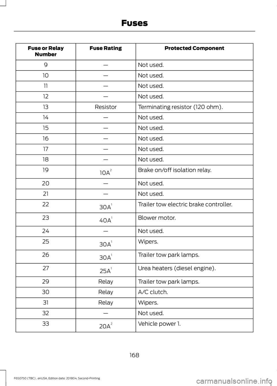
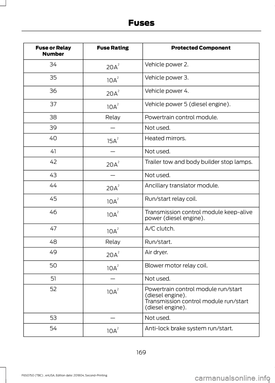
FUSE SPECIFICATION CHART
Power Distribution Box
WARNING: Always disconnect the
battery before servicing high current
fuses. WARNING: To reduce risk of
electrical shock, always replace the
cover to the power distribution box
before reconnecting the battery or
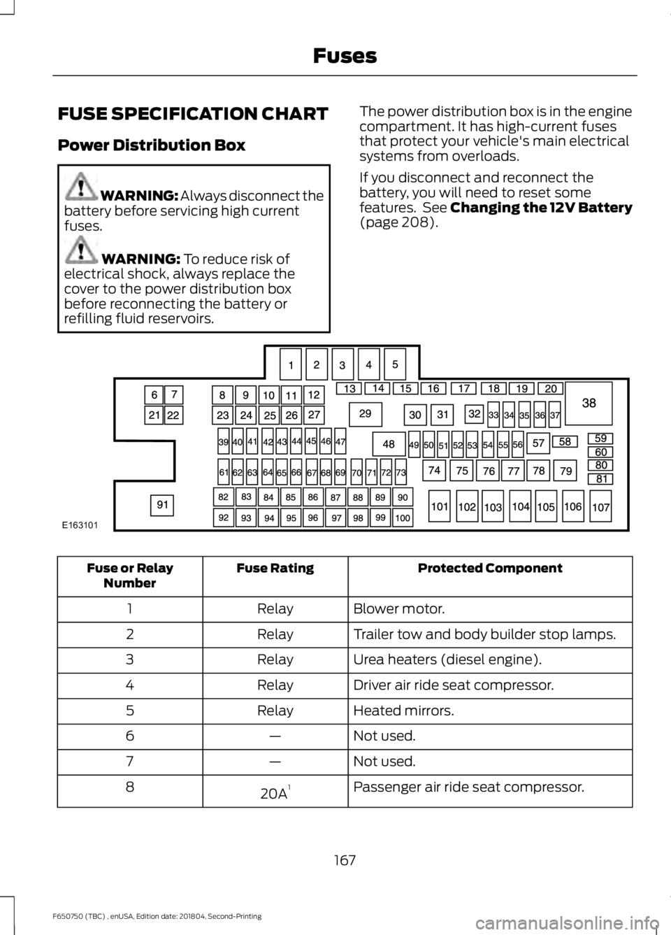
refilling fluid reservoirs. The power distribution box is in the engine
compartment. It has high-current fuses
that protect your vehicle's main electrical
systems from overloads.
If you disconnect and reconnect the
battery, you will need to reset some
features. See Changing the 12V Battery
(page
208). Protected Component
Fuse Rating
Fuse or Relay
Number
Blower motor.
Relay
1
Trailer tow and body builder stop lamps.
Relay
2
Urea heaters (diesel engine).
Relay
3
Driver air ride seat compressor.
Relay
4
Heated mirrors.
Relay
5
Not used.
—
6
Not used.
—
7
Passenger air ride seat compressor.
20A 1
8
167
F650750 (TBC) , enUSA, Edition date: 201804, Second-Printing FusesE163101
Page 171 of 387
Protected Component
Fuse Rating
Fuse or Relay
Number
Not used.
—
9
Not used.
—
10
Not used.
—
11
Not used.
—
12
Terminating resistor (120 ohm).
Resistor
13
Not used.
—
14
Not used.
—
15
Not used.
—
16
Not used.
—
17
Not used.
—
18
Brake on/off isolation relay.
10A 2
19
Not used.
—
20
Not used.
—
21
Trailer tow electric brake controller.
30A 1
22
Blower motor.
40A 1
23
Not used.
—
24
Wipers.
30A 1
25
Trailer tow park lamps.
30A 1
26
Urea heaters (diesel engine).
25A 1
27
Trailer tow park lamps.
Relay
29
A/C clutch.
Relay
30
Wipers.
Relay
31
Not used.
—
32
Vehicle power 1.
20A 2
33
168
F650750 (TBC) , enUSA, Edition date: 201804, Second-Printing Fuses
Page 172 of 387
Protected Component
Fuse Rating
Fuse or Relay
Number
Vehicle power 2.
20A 2
34
Vehicle power 3.
10A 2
35
Vehicle power 4.
20A 2
36
Vehicle power 5 (diesel engine).
10A 2
37
Powertrain control module.
Relay
38
Not used.
—
39
Heated mirrors.
15A 2
40
Not used.
—
41
Trailer tow and body builder stop lamps.
20A 2
42
Not used.
—
43
Ancillary translator module.
20A 2
44
Run/start relay coil.
10A 2
45
Transmission control module keep-alive
power (diesel engine).
10A 2
46
A/C clutch.
10A 2
47
Run/start.
Relay
48
Air dryer.
20A 2
49
Blower motor relay coil.
10A 2
50
Not used.
—
51
Powertrain control module run/start
(diesel engine).
10A 2
52
Transmission control module run/start
(diesel engine).
Not used.
—
53
Anti-lock brake system run/start.
10A 2
54
169
F650750 (TBC) , enUSA, Edition date: 201804, Second-Printing Fuses