FORD FIESTA 2007 Workshop Manual
Manufacturer: FORD, Model Year: 2007, Model line: FIESTA, Model: FORD FIESTA 2007Pages: 1226, PDF Size: 61.26 MB
Page 101 of 1226
204-01 -3 Front Suspension 204-01 -3
DESCRIPTION AND OPERATION
Front Suspension
Overview
N0TE:During installation of the front wheel bearing
it is important to adhere to the specified installation
position, as the anti-lock brake system
( ABS )
sensor ring is located in the wheel bearing. A
coloured rubber ring is provided to indicate the
correct installation position. If the wheel bearing
were to be installed incorrectly then this would
cause failure of the ABS
.
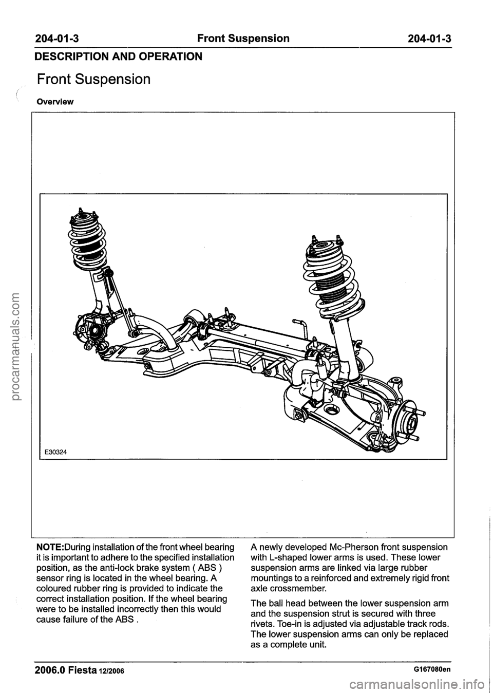
A newly developed Mc-Pherson front suspension
with L-shaped lower arms is used. These lower
suspension arms are linked via large rubber
mountings to a reinforced and extremely rigid front
axle crossmember.
The ball head between the lower suspension arm
and the suspension strut is secured with three
rivets. Toe-in is adjusted via adjustable track rods.
The lower suspension arms can only be replaced as a complete unit.
2006.0 Fiesta IZIZOO~ GI 67080en
procarmanuals.com
Page 102 of 1226
204101 -4 Front Suspension 204-01 -4
DESCRIPTION
AND OPERATION
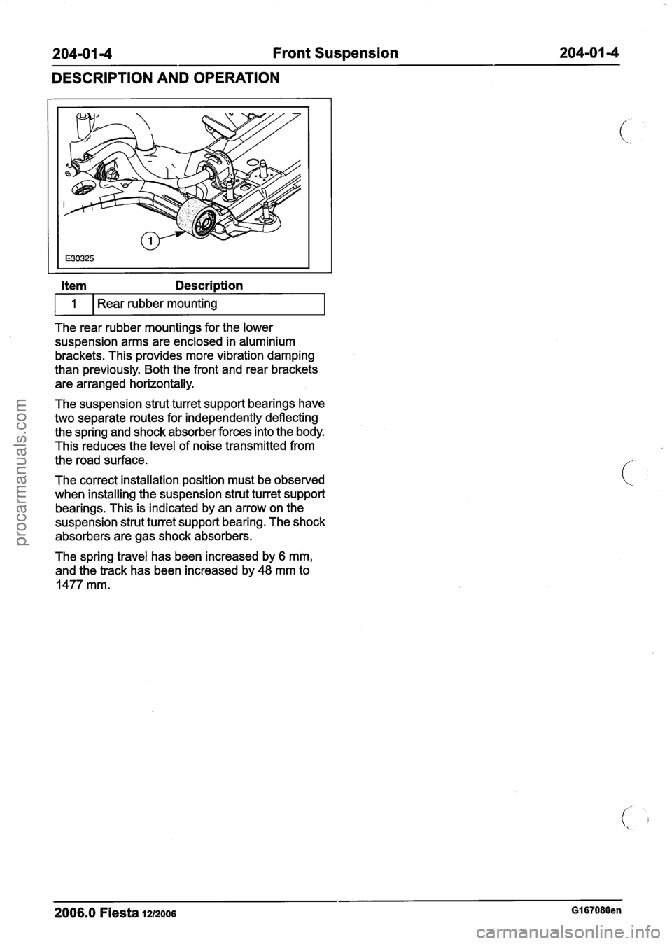
Item Description
The rear rubber mountings for the lower
suspension arms are enclosed in aluminium
brackets. This provides more vibration damping
than previously. Both the front and rear brackets
are arranged horizontally.
1
The suspension strut turret support bearings have
two separate routes for independently deflecting
the spring and shock absorber forces into the body.
This reduces the level of noise transmitted from
the road surface. Rear rubber
mounting
The correct installation position must be observed
when installing the suspension strut turret support
bearings. This is indicated by an arrow on the
suspension strut turret support bearing. The shock
absorbers are gas shock absorbers.
The spring travel has been increased by
6 mm,
and the track has been increased by
48 mm to
1477 mm.
2006.0 Fiesta 1212006 GI 67080en
procarmanuals.com
Page 103 of 1226
![FORD FIESTA 2007 Workshop Manual
204-01 -5 Front Suspension 204-01 -5
DIAGNOSIS AND TESTING
Front Suspension
! REFER to Section 204-00 [Suspension System -
General Information].
2006.0 Fiesta 1212006 GI 7395en
procarmanua FORD FIESTA 2007 Workshop Manual
204-01 -5 Front Suspension 204-01 -5
DIAGNOSIS AND TESTING
Front Suspension
! REFER to Section 204-00 [Suspension System -
General Information].
2006.0 Fiesta 1212006 GI 7395en
procarmanua](/img/11/56936/w960_56936-102.png)
204-01 -5 Front Suspension 204-01 -5
DIAGNOSIS AND TESTING
Front Suspension
! REFER to Section 204-00 [Suspension System -
General Information].
2006.0 Fiesta 1212006 GI 7395en
procarmanuals.com
Page 104 of 1226
204-01 -6 Front Suspension 204-01 -6
REMOVAL AND INSTALLATION
Front Stabilizer Bar Bushing(l4 754 0)
Removal 2. Install the stabilizer bar.
1. Remove the stabilizer bar.
For additional information, refer to Stabilizer
Bar in this section.
2. Remove the stabilizer bar bushings on both
sides. For
additional information, refer to Stabilizer
Bar in this section.
Installation
1. CAUTIONS:
ADO not lubricate the stabilizer bar
bushings.
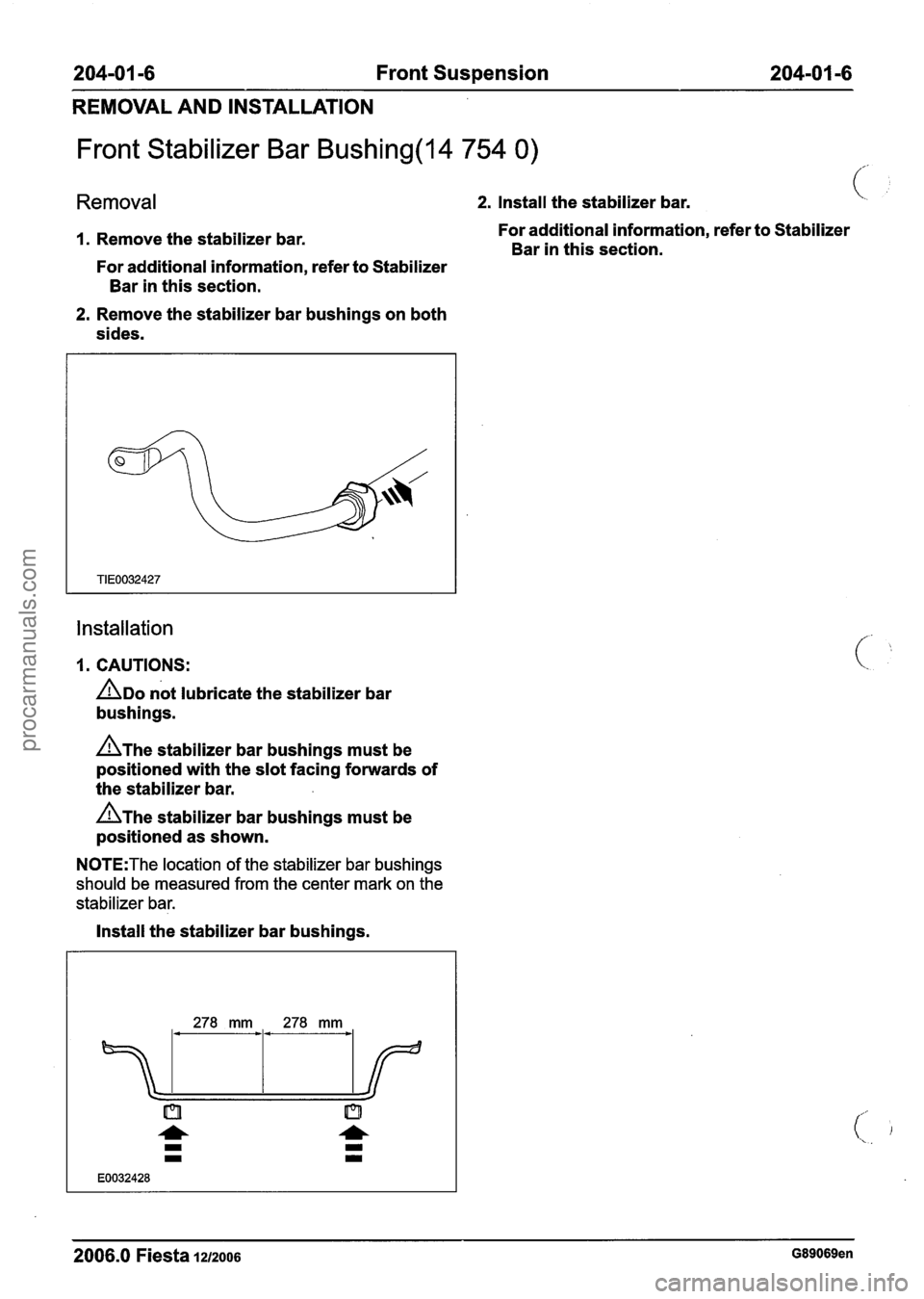
AThe stabilizer bar bushings must be
positioned with the slot facing forwards of
the stabilizer bar.
AThe stabilizer bar bushings must be
positioned as shown.
N0TE:The location of the stabilizer bar bushings
should be measured from the center mark on the
stabilizer bar.
Install the stabilizer bar bushings.
2006.0 Fiesta 1212006 G89069en
procarmanuals.com
Page 105 of 1226

204-0 I -7 Front Suspension 204-0 1 -7
REMOVAL AND INSTALLATION
Lower Arm(l4 706 0)
Removal
1. Remove the wheel and tire. For additional
information, refer to Section
204-04 [Wheels
and Tires].
2m ncAu~10N:~rotect the ball joint seal using
a soft cloth to prevent damage.
Detach the lower arm ball joint from the
wheel knuckle.
Remove the heat shield.
3. Remove the crossmember outer retaining
bolt.
4. Remove the lower arm.
Installation
1. N0TE:Do not fully tighten the lower arm to
crossmember retaining bolts at this stage.
Install the lower arm.
2. Install the crossmember outer retaining bolt.
3m ~CAUTION:M~~~ sure the heat shield is
installed to prevent damage to the ball joint.
2006.0 Fiesta 1212006 GI 83757en
procarmanuals.com
Page 106 of 1226
204-0 I -8 Front Suspension 204-01 -8
REMOVAL AND INSTALLATION
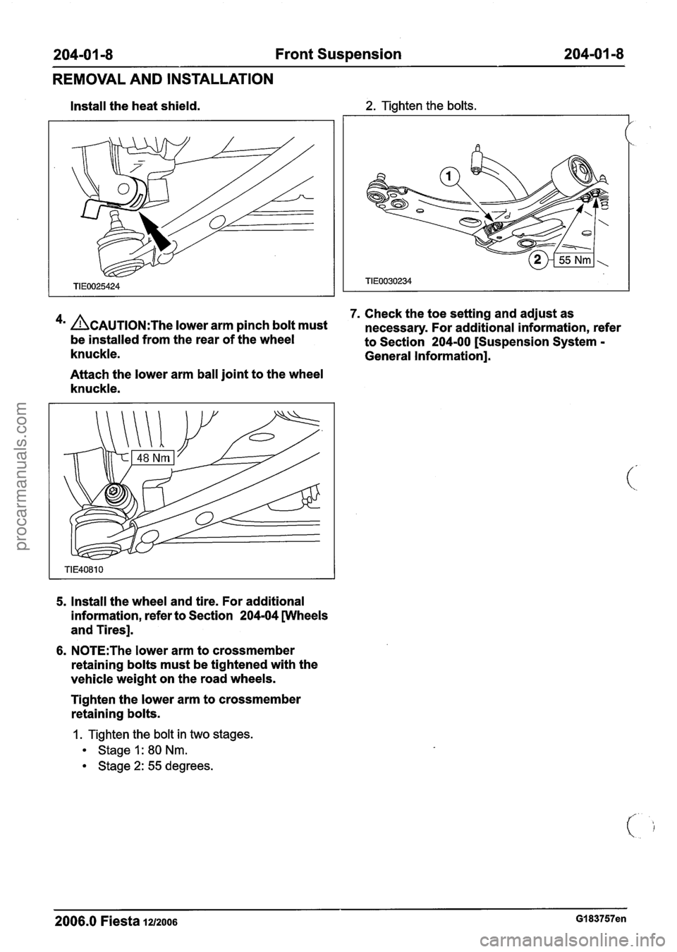
Install the heat shield. 2. Tighten the bolts.
7. Check the toe setting and adjust as
4m ACAUTION:T~~ lower arm pinch bolt must necessary. For additional information, refer
be installed from the rear of the wheel
to Section 204-00 [Suspension System -
knuckle. General Information].
Attach the lower arm ball joint to the wheel
knuckle.
5, Install the wheel and tire. For additional
information, refer to Section
204-04 wheels
and Tires].
6. N0TE:The lower arm to crossmember
retaining bolts must be tightened with the
vehicle weight on the road wheels.
Tighten the lower arm to crossmember
retaining bolts.
1. Tighten the bolt in two stages.
Stage I: 80 Nm.
Stage 2: 55 degrees.
2006.0 Fiesta 1212006 GI 83757en
procarmanuals.com
Page 107 of 1226
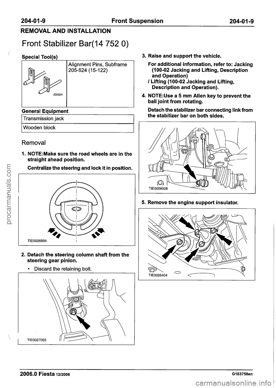
204-01 -9 Front Suspension 204-0 I -9
REMOVAL AND INSTALLATION
Front Stabilizer Bar(l4 752 0)
i , Special Tool(s1
General Equipment
205524
I Transmission jack 1
Alignment Pins, Subframe
205-524 (1 5-1 22)
I Wooden block I
Removal
1. N0TE:Make sure the road wheels are in the
straight ahead position.
Centralize the steering and lock
it in position.
2. Detach the steering column shaft from the
steering gear pinion.
Discard the retaining bolt.
3. Raise and support the vehicle.
For additional information, refer to: Jacking
(100-02 Jacking and Lifting, Description
and Operation)
I Lifting (1 00-02 Jacking and Lifting,
Description and Operation).
4. N0TE:Use a 5 mm Allen key to prevent the
ball joint from rotating.
Detach the stabilizer bar connecting link from
the stabilizer bar on both sides.
5. Remove the engine support insulator.
2006.0 Fiesta 1212006 GI 83758en
procarmanuals.com
Page 108 of 1226
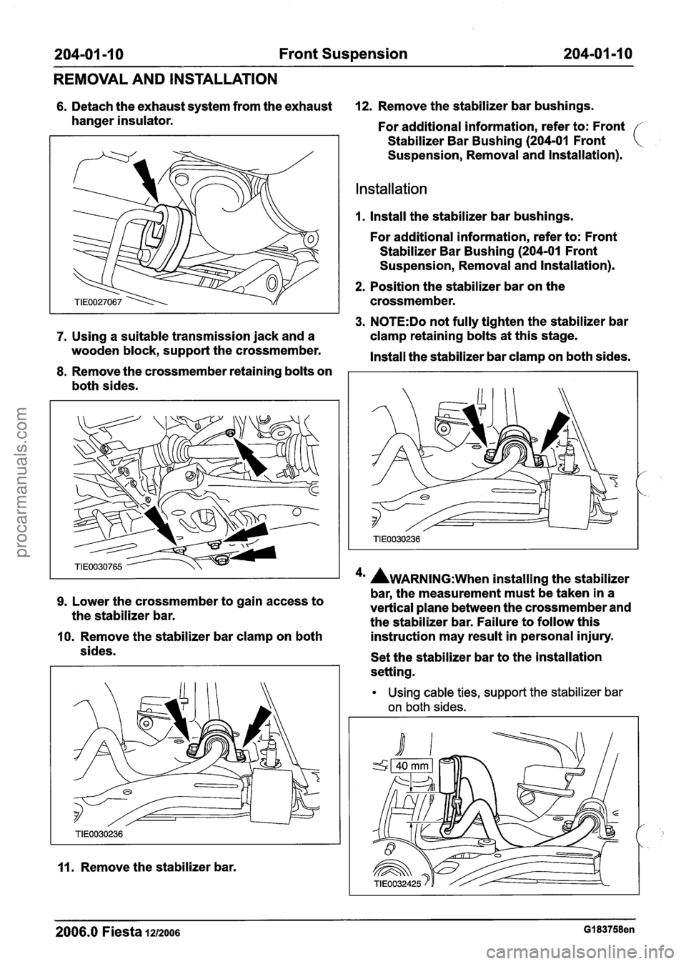
204-01 -1 0 Front Suspension 204-01 -1 0
REMOVAL AND INSTALLATION
6. Detach the exhaust system from the exhaust 12. Remove the stabilizer bar bushings.
hanger insulator. For additional information, refer to: Front
Stabilizer Bar Bushing
(204-01 Front
Suspension, Removal and lnstallation).
Installation
1. Install the stabilizer bar bushings.
For additional information, refer to: Front
Stabilizer Bar Bushing
(204-01 Front
Suspension, Removal and lnstallation).
2. Position the stabilizer bar on the
crossmember.
3. N0TE:Do not fully tighten the stabilizer bar
7. Using a suitable transmission jack and a clamp
retaining bolts at this stage.
wooden block, support the crossmember.
Install the stabilizer bar clamp on both sides.
8. Remove the crossmember retaining bolts on
both sides.
4' AWARNING:~~~~ installing the stabilizer
bar, the measurement must be taken in a
9. Lower the crossmember to gain access to
the stabilizer bar. vertical plane
between the crossmember and
the stabilizer bar. Failure to follow this
10. Remove the stabilizer bar clamp on both instruction
may result in personal injury.
sides. Set the stabilizer bar to the installation
setting.
11. Remove the stabilizer bar.
Using cable ties, support the stabilizer bar
on both sides.
2006.0 Fiesta 1212006 GI 83758en
procarmanuals.com
Page 109 of 1226
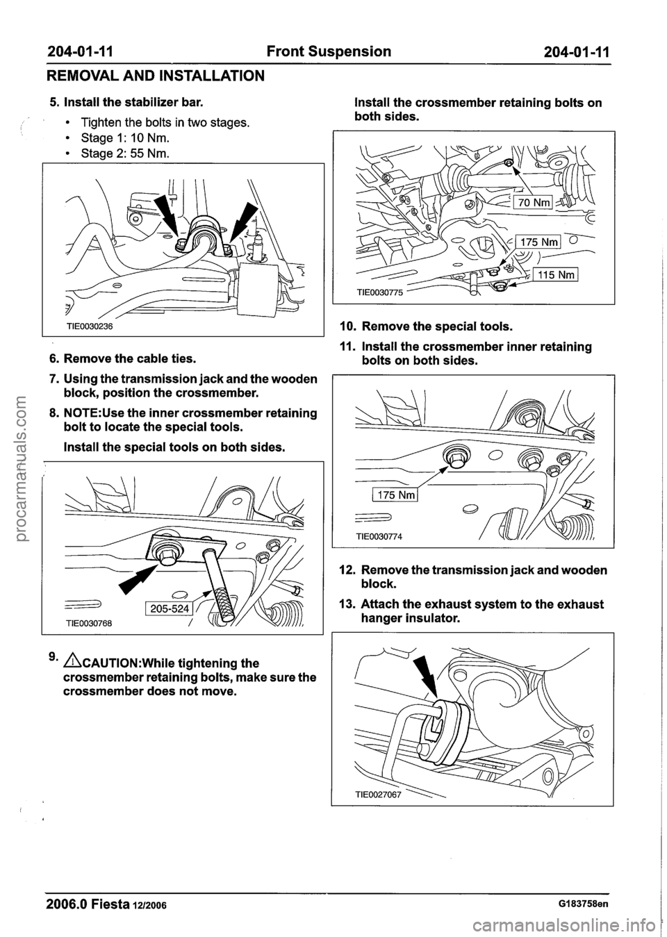
204-01 -1 I Front Suspension 204-01 -1 1
REMOVAL AND INSTALLATION
5. Install the stabilizer bar.
i Tighten the bolts in two stages. Stage 1 : 10 Nm.
Stage 2: 55 Nm.
6. Remove the cable ties.
7. Using the transmission jack and the wooden
block, position the crossmember.
8. N0TE:Use the inner crossmember retaining
bolt to locate the special tools.
Install the special tools on both sides.
&AUTION:W~~I~ tightening the
crossmember retaining bolts, make sure the
crossmember does not move. Install the
crossmember retaining bolts on
both sides.
10. Remove the special tools.
11. Install the crossmember inner retaining
bolts on both sides.
12. Remove the transmission jack and wooden
block.
13. Attach the exhaust system to the exhaust
hanger insulator.
2006.0 Fiesta 12/2006 GI 83758en
procarmanuals.com
Page 110 of 1226
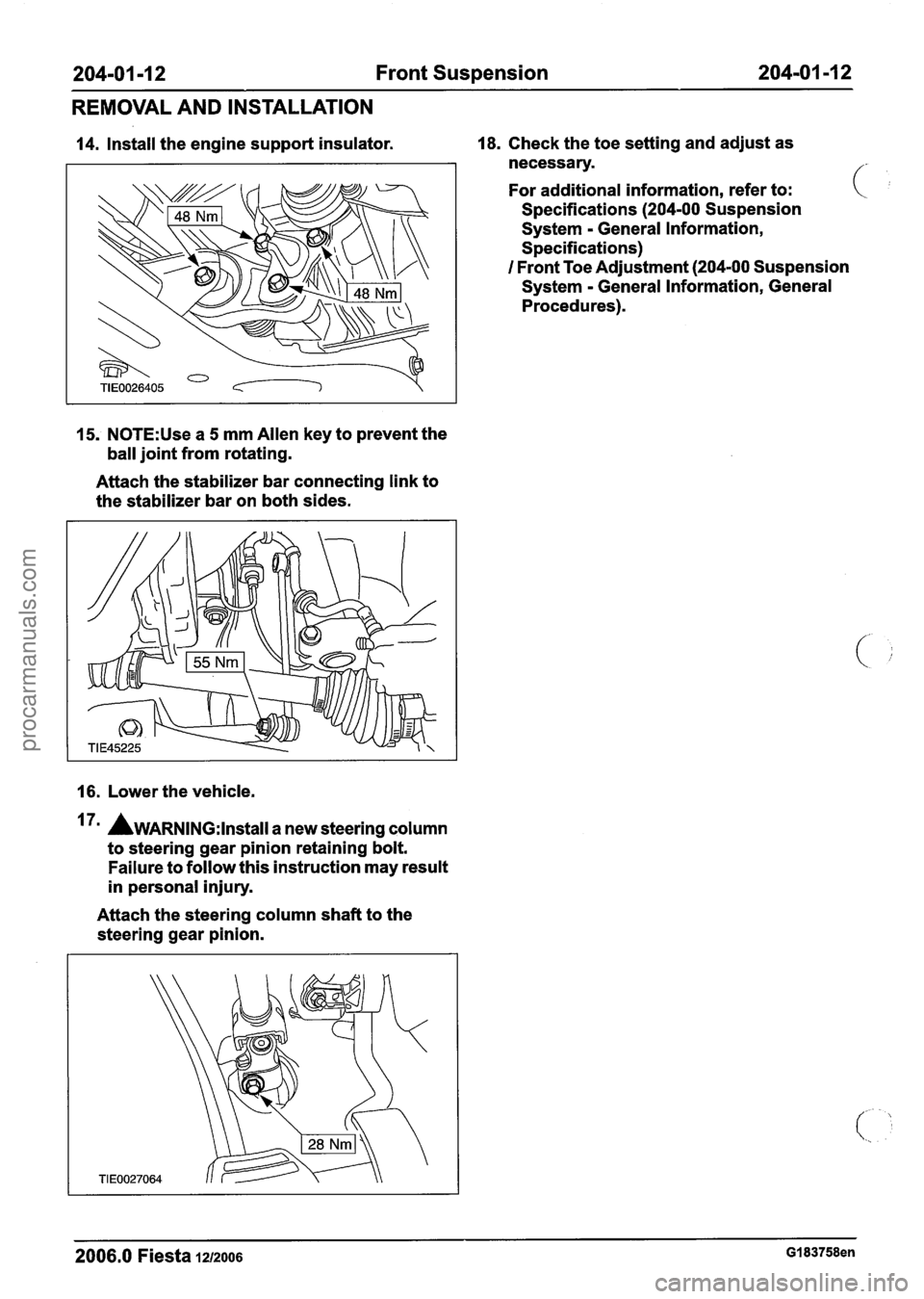
204-01 -1 2 Front Suspension 204-01 -1 2 ---- - -
REMOVAL AND INSTALLATION
14. Install the engine support insulator. 18. Check the toe setting and adjust as
necessary.
For additional information, refer to:
Specifications
(204-00 Suspension
System
- General Information,
Specifications)
I Front Toe Adjustment (204-00 Suspension
System
- General Information, General
Procedures).
15. N0TE:Use a 5 mm Allen key to prevent the
ball joint from rotating.
Attach the stabilizer bar connecting link to
the stabilizer bar on both sides.
16. Lower the vehicle.
7m AWARNING:I~~~~II a new steering column
to steering gear pinion retaining bolt.
Failure to follow this instruction may result
in personal injury.
Attach the steering column shaft to the
steering gear pinion.
2006.0 Fiesta 1212006 GI 83758en
procarmanuals.com