headlamp FORD FLEX 2014 1.G User Guide
[x] Cancel search | Manufacturer: FORD, Model Year: 2014, Model line: FLEX, Model: FORD FLEX 2014 1.GPages: 554, PDF Size: 8.04 MB
Page 241 of 554
System Limitations
WARNING:The collision warning system’s brake support can
only help reduce the speed at which a collision occurs if the
driver applies the vehicle’s brakes. The brake pedal must be pressed
just like any typical braking situation.
Due to the nature of radar technology, there may be certain instances
where vehicles do not provide a collision warning. These include:
•Stationary vehicles or vehicles moving below 6 mph (10 km/h).
•Pedestrians or objects in the roadway.
•Oncoming vehicles in the same lane.
•Severe weather conditions (see blocked sensor section).
•Debris build-up on the grille near the headlamps (see blocked sensor
section).
•Small distance to vehicle ahead.
•Steering wheel and pedal movements are large (very active driving
style).
•High interior temperatures, which may deactivate the illumination or
the warning lamps until the interior temperature reduces (audible
warning still sounds).
Certain conditions may reduce the visibility of the warning lamp;
therefore, it is recommended to keep the audible warning on.
If the front end of the vehicle is hit or damaged, the radar sensing zone
may be altered causing missed or false collision warnings. See your
authorized dealer to have your collision warning radar checked for
proper coverage and operation.
STEERING
Electric Power Steering
WARNING:The electric power steering system has diagnostic
checks that continuously monitor the system to ensure proper
operation. When a system error is detected a steering message will
appear in the information display.
240Driving Aids
2014 Flex(471)
Owners Guide gf, 1st Printing, April 2013
USA(fus)
Page 282 of 554
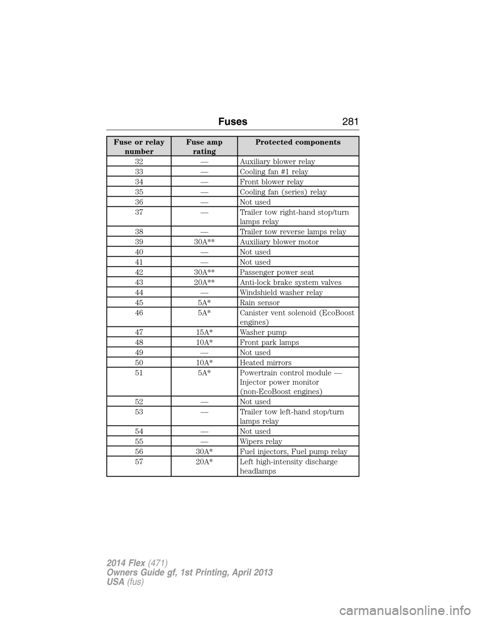
Fuse or relay
numberFuse amp
ratingProtected components
32 — Auxiliary blower relay
33 — Cooling fan #1 relay
34 — Front blower relay
35 — Cooling fan (series) relay
36 — Not used
37 — Trailer tow right-hand stop/turn
lamps relay
38 — Trailer tow reverse lamps relay
39 30A** Auxiliary blower motor
40 — Not used
41 — Not used
42 30A** Passenger power seat
43 20A** Anti-lock brake system valves
44 — Windshield washer relay
45 5A* Rain sensor
46 5A* Canister vent solenoid (EcoBoost
engines)
47 15A* Washer pump
48 10A* Front park lamps
49 — Not used
50 10A* Heated mirrors
51 5A* Powertrain control module —
Injector power monitor
(non-EcoBoost engines)
52 — Not used
53 — Trailer tow left-hand stop/turn
lamps relay
54 — Not used
55 — Wipers relay
56 30A* Fuel injectors, Fuel pump relay
57 20A* Left high-intensity discharge
headlamps
Fuses281
2014 Flex(471)
Owners Guide gf, 1st Printing, April 2013
USA(fus)
Page 284 of 554
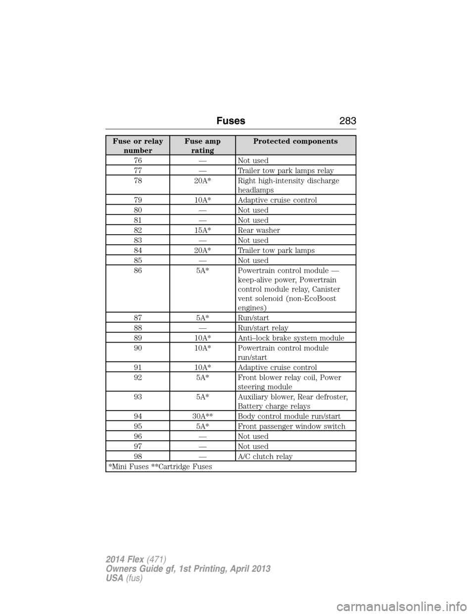
Fuse or relay
numberFuse amp
ratingProtected components
76 — Not used
77 — Trailer tow park lamps relay
78 20A* Right high-intensity discharge
headlamps
79 10A* Adaptive cruise control
80 — Not used
81 — Not used
82 15A* Rear washer
83 — Not used
84 20A* Trailer tow park lamps
85 — Not used
86 5A* Powertrain control module —
keep-alive power, Powertrain
control module relay, Canister
vent solenoid (non-EcoBoost
engines)
87 5A* Run/start
88 — Run/start relay
89 10A* Anti–lock brake system module
90 10A* Powertrain control module
run/start
91 10A* Adaptive cruise control
92 5A* Front blower relay coil, Power
steering module
93 5A* Auxiliary blower, Rear defroster,
Battery charge relays
94 30A** Body control module run/start
95 5A* Front passenger window switch
96 — Not used
97 — Not used
98 — A/C clutch relay
*Mini Fuses **Cartridge Fuses
Fuses283
2014 Flex(471)
Owners Guide gf, 1st Printing, April 2013
USA(fus)
Page 286 of 554
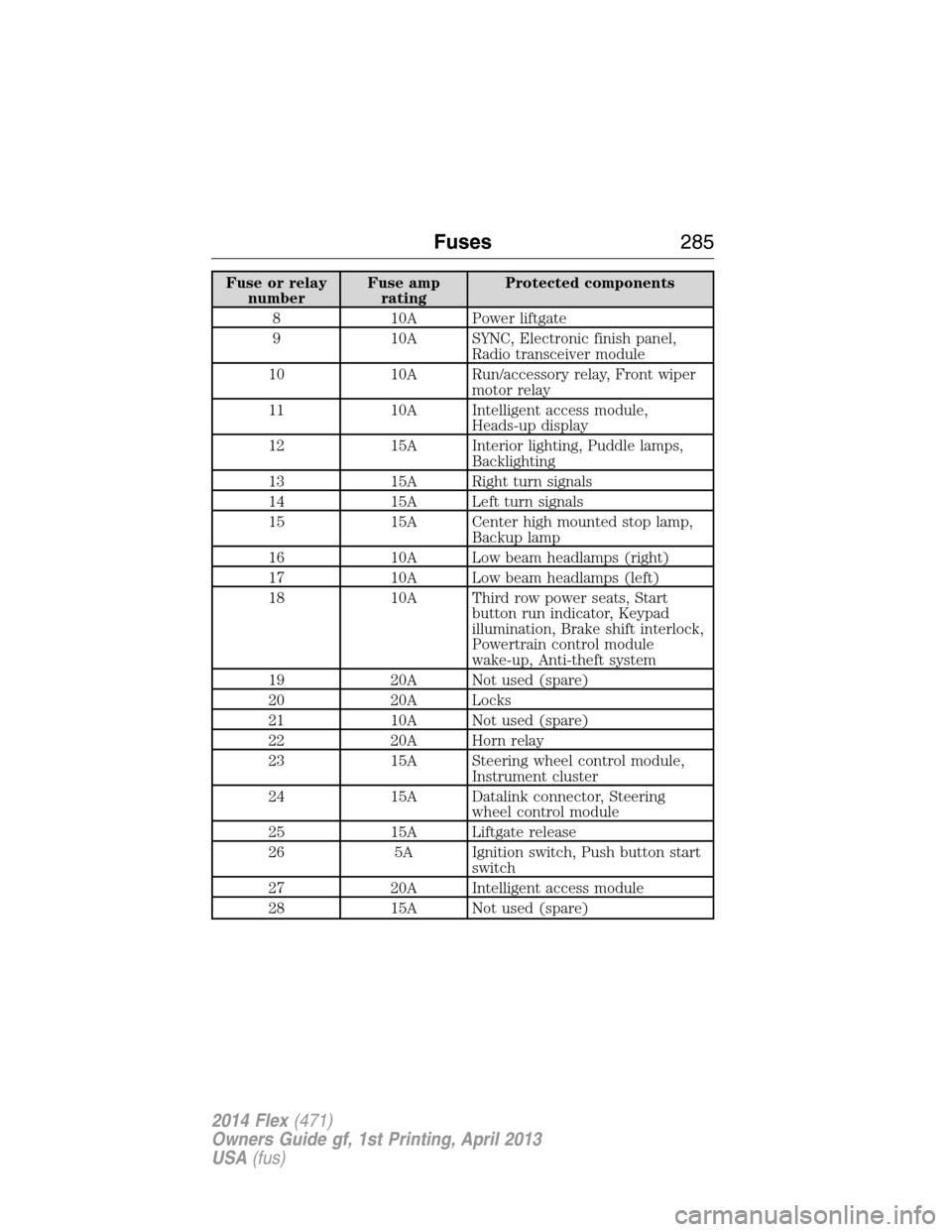
Fuse or relay
numberFuse amp
ratingProtected components
8 10A Power liftgate
9 10A SYNC, Electronic finish panel,
Radio transceiver module
10 10A Run/accessory relay, Front wiper
motor relay
11 10A Intelligent access module,
Heads-up display
12 15A Interior lighting, Puddle lamps,
Backlighting
13 15A Right turn signals
14 15A Left turn signals
15 15A Center high mounted stop lamp,
Backup lamp
16 10A Low beam headlamps (right)
17 10A Low beam headlamps (left)
18 10A Third row power seats, Start
button run indicator, Keypad
illumination, Brake shift interlock,
Powertrain control module
wake-up, Anti-theft system
19 20A Not used (spare)
20 20A Locks
21 10A Not used (spare)
22 20A Horn relay
23 15A Steering wheel control module,
Instrument cluster
24 15A Datalink connector, Steering
wheel control module
25 15A Liftgate release
26 5A Ignition switch, Push button start
switch
27 20A Intelligent access module
28 15A Not used (spare)
Fuses285
2014 Flex(471)
Owners Guide gf, 1st Printing, April 2013
USA(fus)
Page 287 of 554
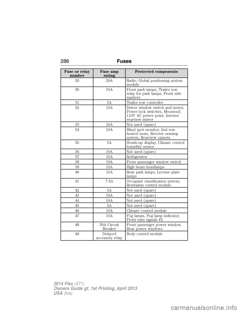
Fuse or relay
numberFuse amp
ratingProtected components
29 20A Radio, Global positioning system
module
30 15A Front park lamps, Trailer tow
relay for park lamps, Front side
markers
31 5A Trailer tow controller
32 15A Driver window switch and motor,
Power lock switches, Moonroof,
110V AC power point, Interior
rearview mirror
33 10A Not used (spare)
34 10A Blind spot monitor, 2nd row
heated seats, Reverse sensing
system, Rearview camera
35 5A Heads-up display, Climate control
humidity sensor
36 10A Not used (spare)
37 10A Refrigerator
38 10A Front passenger window switch
39 15A High beam headlamps
40 10A Rear park lamps, License plate
lamps
41 7.5A Occupant classification system,
Restraints control module
42 5A Not used (spare)
43 10A Not used (spare)
44 10A Not used (spare)
45 5A Not used (spare)
46 10A Climate control module
47 15A Fog lamps, Fog lamp indicator,
Front turn signals #2
48 30A Circuit
BreakerFront passenger power window,
Rear power windows
49 Delayed
accessory relayBody control module
286Fuses
2014 Flex(471)
Owners Guide gf, 1st Printing, April 2013
USA(fus)
Page 309 of 554
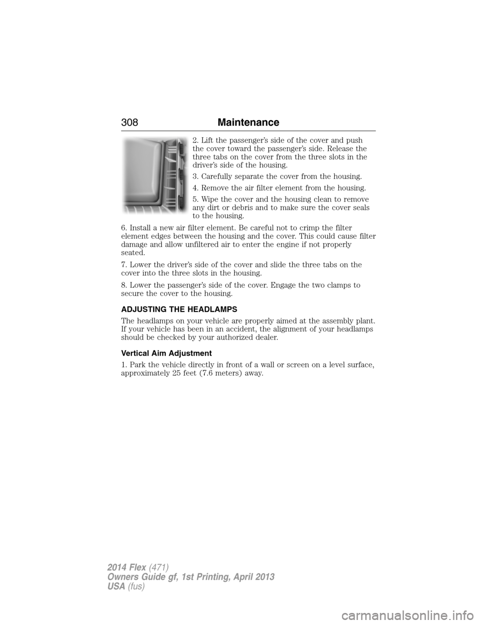
2. Lift the passenger’s side of the cover and push
the cover toward the passenger’s side. Release the
three tabs on the cover from the three slots in the
driver’s side of the housing.
3. Carefully separate the cover from the housing.
4. Remove the air filter element from the housing.
5. Wipe the cover and the housing clean to remove
any dirt or debris and to make sure the cover seals
to the housing.
6. Install a new air filter element. Be careful not to crimp the filter
element edges between the housing and the cover. This could cause filter
damage and allow unfiltered air to enter the engine if not properly
seated.
7. Lower the driver’s side of the cover and slide the three tabs on the
cover into the three slots in the housing.
8. Lower the passenger’s side of the cover. Engage the two clamps to
secure the cover to the housing.
ADJUSTING THE HEADLAMPS
The headlamps on your vehicle are properly aimed at the assembly plant.
If your vehicle has been in an accident, the alignment of your headlamps
should be checked by your authorized dealer.
Vertical Aim Adjustment
1. Park the vehicle directly in front of a wall or screen on a level surface,
approximately 25 feet (7.6 meters) away.
308Maintenance
2014 Flex(471)
Owners Guide gf, 1st Printing, April 2013
USA(fus)
Page 310 of 554
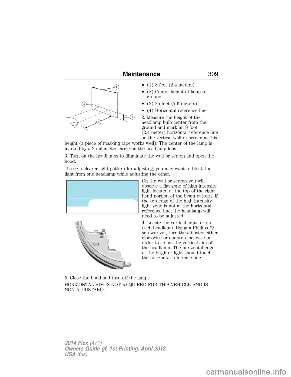
•(1) 8 feet (2.4 meters)
•(2) Center height of lamp to
ground
•(3) 25 feet (7.6 meters)
•(4) Horizontal reference line
2. Measure the height of the
headlamp bulb center from the
ground and mark an 8 foot
(2.4 meter) horizontal reference line
on the vertical wall or screen at this
height (a piece of masking tape works well). The center of the lamp is
marked bya3millimeter circle on the headlamp lens
3. Turn on the headlamps to illuminate the wall or screen and open the
hood.
To see a clearer light pattern for adjusting, you may want to block the
light from one headlamp while adjusting the other.
On the wall or screen you will
observe a flat zone of high intensity
light located at the top of the right
hand portion of the beam pattern. If
the top edge of the high intensity
light zone is not at the horizontal
reference line, the headlamp will
need to be adjusted.
4. Locate the vertical adjuster on
each headlamp. Using a Phillips #2
screwdriver, turn the adjuster either
clockwise or counterclockwise in
order to adjust the vertical aim of
the headlamp. The horizontal edge
of the brighter light should touch
the horizontal reference line.
5. Close the hood and turn off the lamps.
HORIZONTAL AIM IS NOT REQUIRED FOR THIS VEHICLE AND IS
NON-ADJUSTABLE.
Maintenance309
2014 Flex(471)
Owners Guide gf, 1st Printing, April 2013
USA(fus)
Page 311 of 554
CHANGING A BULB
Lamp Assembly Condensation
Exterior lamps are vented to accommodate normal changes in pressure.
Condensation can be a natural by-product of this design. When moist air
enters the lamp assembly through the vents, there is a possibility that
condensation can occur when the temperature is cold. When normal
condensation occurs, a thin film of mist can form on the interior of the
lens. The thin mist eventually clears and exits through the vents during
normal operation. Clearing time may take as long as 48 hours under dry
weather conditions.
These are examples of acceptable condensation:
•Presence of thin mist (no streaks, drip marks or droplets).
•Fine mist covers less than 50% of the lens.
These are examples of unacceptable moisture (usually caused by a lamp
water leak):
•Water puddle inside the lamp.
•Large water droplets, drip marks or streaks present on the interior of
the lens.
Take your vehicle to a dealer for service if any of the above conditions of
unacceptable moisture are present.
Replacing headlamp bulbs
WARNING:Handle a halogen headlamp bulb carefully and keep
out of children’s reach. Grasp the bulb only by its plastic base
and do not touch the glass. The oil from your hand could cause the
bulb to break the next time the headlamps are operated.
Note:If the bulb is accidentally touched, it should be cleaned with
rubbing alcohol before being used.
1. Make sure headlamp switch is in the off position, then open the hood.
2. Reach in behind the headlamp assembly to access the bulb sockets
and connectors.
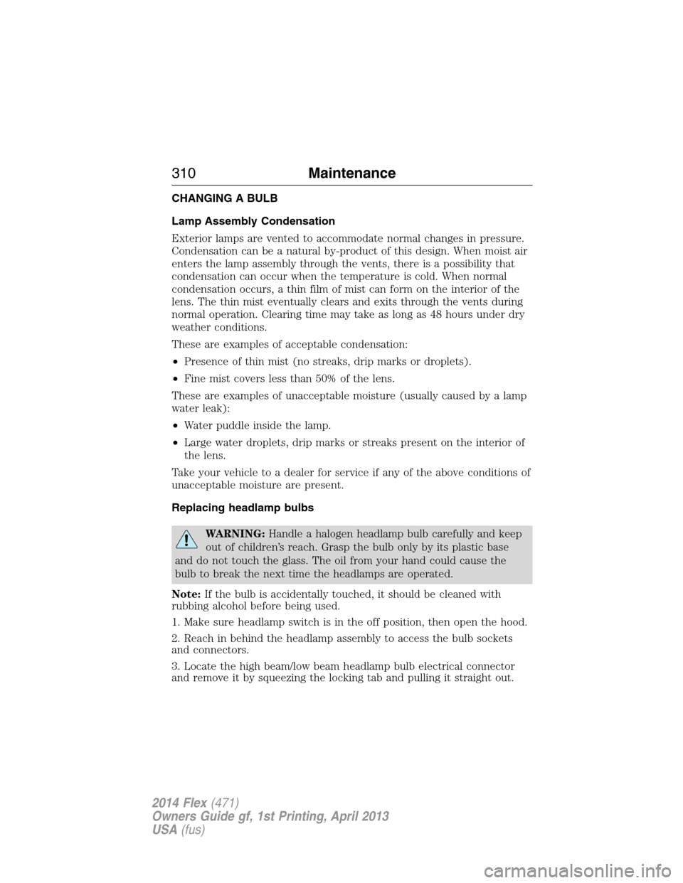
3. Locate the high beam/low beam headlamp bulb electrical connector
and remove it by squeezing the locking tab and pulling it straight out.
310Maintenance
2014 Flex(471)
Owners Guide gf, 1st Printing, April 2013
USA(fus)
Page 312 of 554
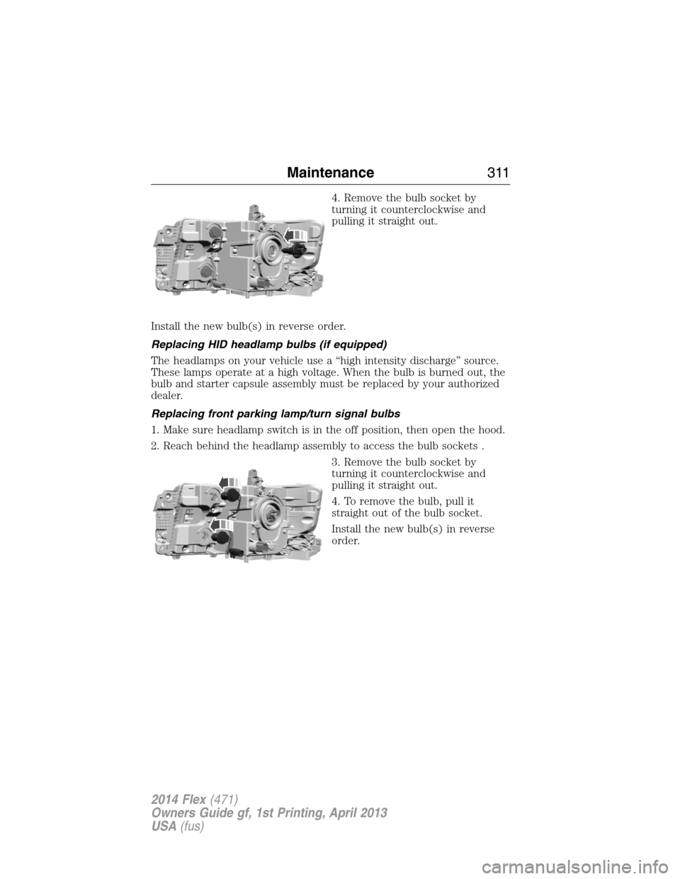
4. Remove the bulb socket by
turning it counterclockwise and
pulling it straight out.
Install the new bulb(s) in reverse order.
Replacing HID headlamp bulbs (if equipped)
The headlamps on your vehicle use a “high intensity discharge” source.
These lamps operate at a high voltage. When the bulb is burned out, the
bulb and starter capsule assembly must be replaced by your authorized
dealer.
Replacing front parking lamp/turn signal bulbs
1. Make sure headlamp switch is in the off position, then open the hood.
2. Reach behind the headlamp assembly to access the bulb sockets .
3. Remove the bulb socket by
turning it counterclockwise and
pulling it straight out.
4. To remove the bulb, pull it
straight out of the bulb socket.
Install the new bulb(s) in reverse
order.
Maintenance311
2014 Flex(471)
Owners Guide gf, 1st Printing, April 2013
USA(fus)
Page 314 of 554
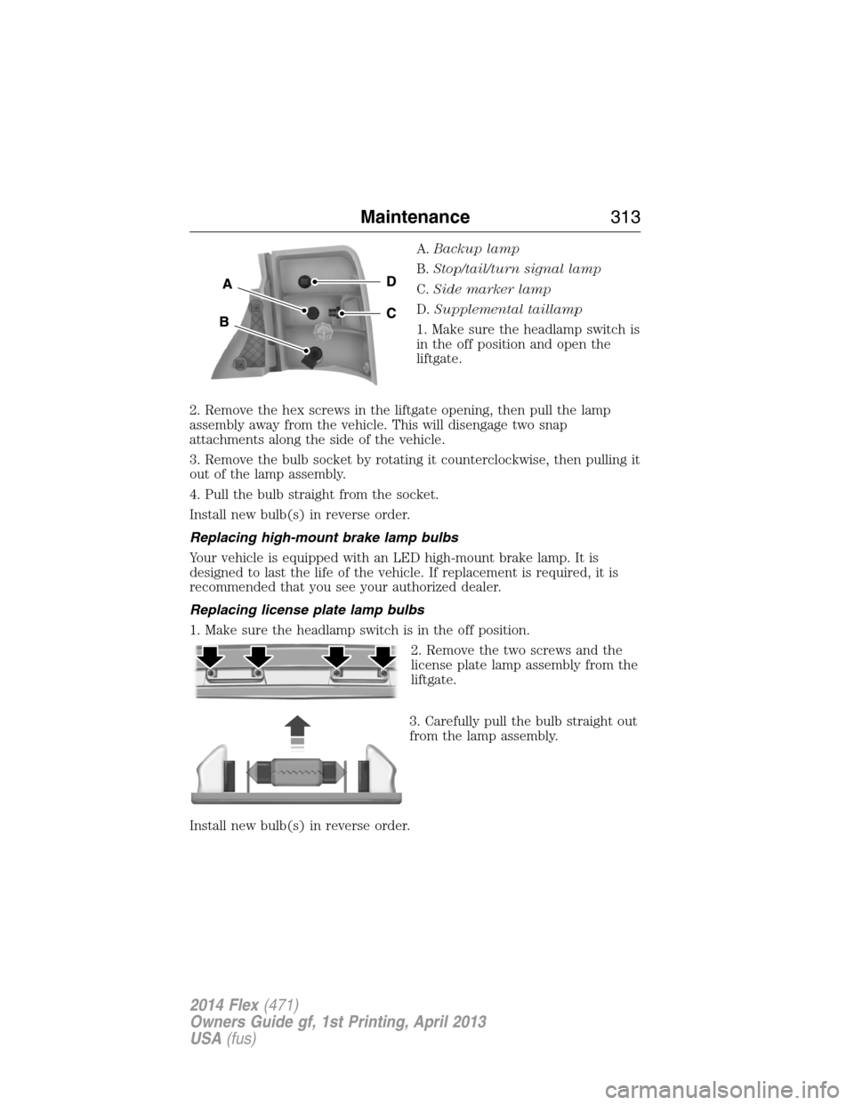
A.Backup lamp
B.Stop/tail/turn signal lamp
C.Side marker lamp
D.Supplemental taillamp
1. Make sure the headlamp switch is
in the off position and open the
liftgate.
2. Remove the hex screws in the liftgate opening, then pull the lamp
assembly away from the vehicle. This will disengage two snap
attachments along the side of the vehicle.
3. Remove the bulb socket by rotating it counterclockwise, then pulling it
out of the lamp assembly.
4. Pull the bulb straight from the socket.
Install new bulb(s) in reverse order.
Replacing high-mount brake lamp bulbs
Your vehicle is equipped with an LED high-mount brake lamp. It is
designed to last the life of the vehicle. If replacement is required, it is
recommended that you see your authorized dealer.
Replacing license plate lamp bulbs
1. Make sure the headlamp switch is in the off position.
2. Remove the two screws and the
license plate lamp assembly from the
liftgate.
3. Carefully pull the bulb straight out
from the lamp assembly.
Install new bulb(s) in reverse order.
Maintenance313
2014 Flex(471)
Owners Guide gf, 1st Printing, April 2013
USA(fus)