FORD MONDEO 1993 Service Repair Manual
Manufacturer: FORD, Model Year: 1993, Model line: MONDEO, Model: FORD MONDEO 1993Pages: 279, PDF Size: 12.71 MB
Page 171 of 279
2Using a trolley jack, support the rear lower
arm beneath the coil spring position.
3Unscrew and remove the bolt securing the
rear shock absorber to the knuckle.
4Where applicable, release the ABS wheel
sensor lead from the tie-bar.
5Detach the handbrake cable from the tie-
bar bracket.
6Refer to Chapter 9, and disconnect the
handbrake cable from the rear brake shoes or
rear caliper, as applicable. Pass the cable
through the hole in the tie-bar.
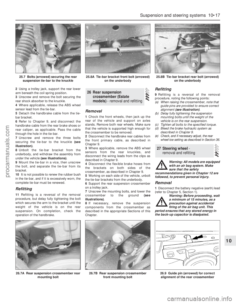
7Unscrew and remove the three bolts
securing the tie-bar to the knuckle (see
illustration).
8Unbolt the tie-bar bracket from the
underbody, and withdraw the assembly from
under the vehicle (see illustrations).
9Mount the tie-bar in a vice, then unscrew
the bolt, and separate the tie-bar from its
bracket.
10It is not possible to renew the rubber bush
in the tie-bar, and if it is excessively worn, the
complete tie-bar must be renewed.
Refitting
11Refitting is a reversal of the removal
procedure, but delay fully tightening the bolt
which secures the arm to the bracket until the
weight of the vehicle is on the rear
suspension. On completion, check the
operation of the handbrake.
Removal
1Chock the front wheels, then jack up the
rear of the vehicle and support on axles
stands. Remove both rear wheels. Make sure
that the vehicle is supported high enough for
the crossmember to be removed.
2Disconnect the handbrake rear cables from
the front primary cable, as described in
Chapter 9.
3Where applicable, remove the ABS wheel
sensors from the rear knuckles, and
disconnect the wiring leads from the clips as
described in Chapter 9.
4Disconnect the flexible brake hoses from
the brackets on both sides of the
crossmember, as described in Chapter 9.
5Working on each side of the vehicle, unbolt
the tie-bar brackets from the underbody.
6Support the rear suspension crossmember
on a trolley jack.
7Unscrew the mounting bolts, and lower the
crossmember to the ground (see
illustrations).
8If necessary, remove the suspension
components from the crossmember as
described in the appropriate Sections of this
Chapter.
Refitting
9Refitting is a reversal of the removal
procedure, noting the following points:
(a) When raising the crossmember, note that
guide pins are provided to ensure correct
alignment (see illustration).
(b) Delay fully tightening the suspension
mounting bolts until the weight of the
vehicle is on the rear suspension.
(c) Tighten all bolts to the specified torque.
(d) Bleed the brake hydraulic system as
described in Chapter 9.
(e) Check, and if necessary adjust, the rear
wheel toe setting as described in Section 36.
Warning: All models are equipped
with an air bag system. Make
sure that the safety
recommendations given in Chapter 12 are
followed, to prevent personal injury.
Removal
1Disconnect the battery negative (earth) lead
(refer to Chapter 5, Section 1).
Warning: Before proceeding, wait
a minimum of 15 minutes, as a
precaution against accidental
firing of the air bag unit. This
period ensures that any stored energy in
the back-up capacitor is dissipated.
27 Steering wheel -
removal and refitting
26 Rear suspension
crossmember (Estate
models) - removal and refitting
Suspension and steering systems 10•17
10
26.7A Rear suspension crossmember rear
mounting bolt26.7B Rear suspension crossmember
front mounting bolt26.9 Guide pin (arrowed) for correct
alignment of the rear crossmember
25.7 Bolts (arrowed) securing the rear
suspension tie-bar to the knuckle25.8A Tie-bar bracket front bolt (arrowed)
on the underbody25.8B Tie-bar bracket rear bolt (arrowed)
on the underbody
procarmanuals.com
Page 172 of 279
2Turn the steering wheel so that the front
wheels are in the straight-ahead position.
3Unscrew the screws, and remove the
steering column upper and lower shrouds.
4From the rear of the steering wheel,
unscrew the air bag module mounting screws.
5Carefully lift the module from the steering
wheel, and disconnect the air bag multi-plug
and horn wiring connections.
Warning: Position the air bag
module in a safe place, with the
mechanism facing downwards as
a precaution against accidental
operation.
6Make sure that the steering lock is not
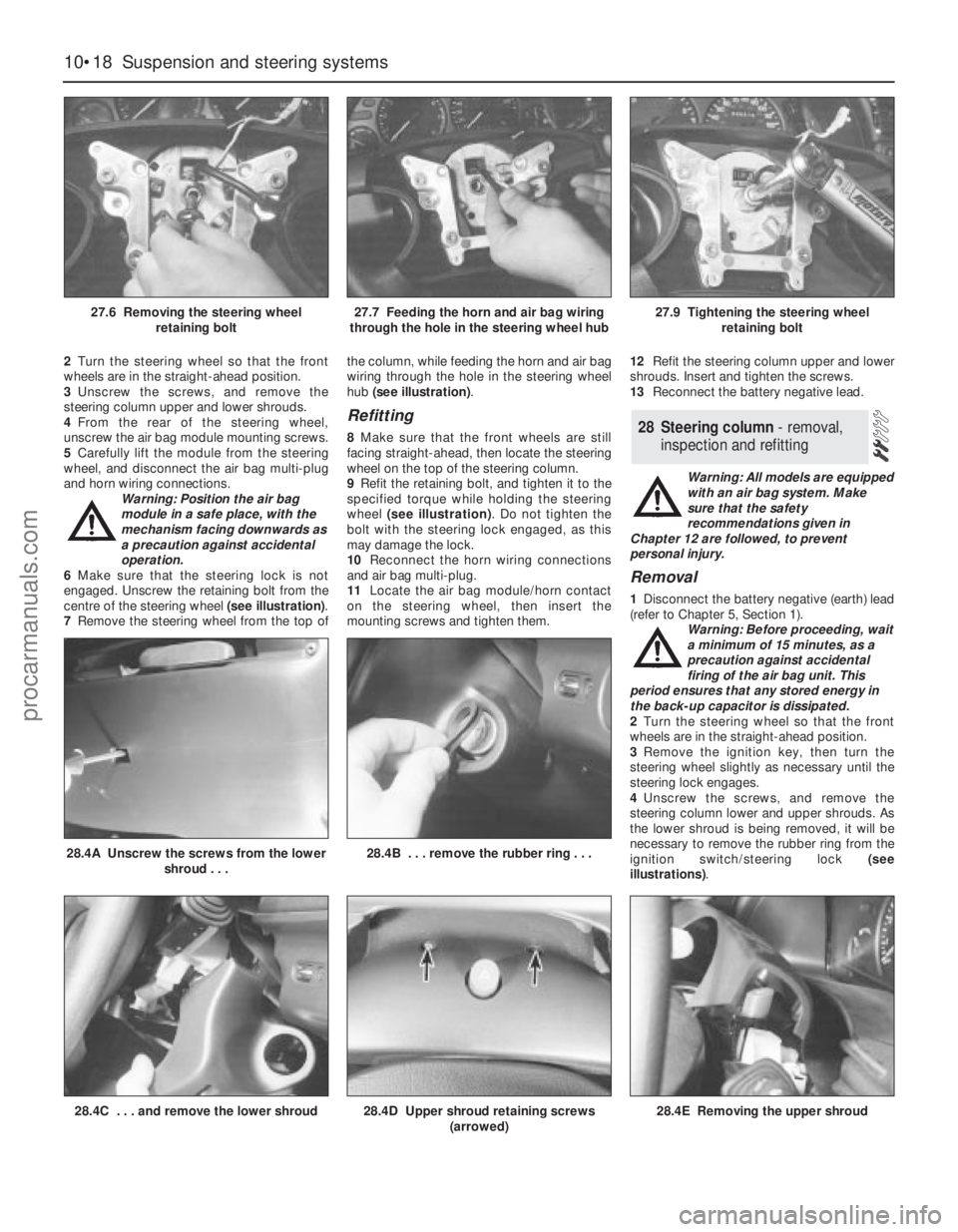
engaged. Unscrew the retaining bolt from the
centre of the steering wheel (see illustration).
7Remove the steering wheel from the top ofthe column, while feeding the horn and air bag
wiring through the hole in the steering wheel
hub (see illustration).
Refitting
8Make sure that the front wheels are still
facing straight-ahead, then locate the steering
wheel on the top of the steering column.
9Refit the retaining bolt, and tighten it to the
specified torque while holding the steering
wheel (see illustration). Do not tighten the
bolt with the steering lock engaged, as this
may damage the lock.
10Reconnect the horn wiring connections
and air bag multi-plug.
11Locate the air bag module/horn contact
on the steering wheel, then insert the
mounting screws and tighten them.12Refit the steering column upper and lower
shrouds. Insert and tighten the screws.
13Reconnect the battery negative lead.
Warning: All models are equipped
with an air bag system. Make
sure that the safety
recommendations given in
Chapter 12 are followed, to prevent
personal injury.
Removal
1Disconnect the battery negative (earth) lead
(refer to Chapter 5, Section 1).
Warning: Before proceeding, wait
a minimum of 15 minutes, as a
precaution against accidental
firing of the air bag unit. This
period ensures that any stored energy in
the back-up capacitor is dissipated.
2Turn the steering wheel so that the front
wheels are in the straight-ahead position.
3Remove the ignition key, then turn the
steering wheel slightly as necessary until the
steering lock engages.
4Unscrew the screws, and remove the
steering column lower and upper shrouds. As
the lower shroud is being removed, it will be
necessary to remove the rubber ring from the
ignition switch/steering lock (see
illustrations).
28 Steering column - removal,
inspection and refitting
10•18 Suspension and steering systems
27.6 Removing the steering wheel
retaining bolt27.7 Feeding the horn and air bag wiring
through the hole in the steering wheel hub27.9 Tightening the steering wheel
retaining bolt
28.4C . . . and remove the lower shroud28.4D Upper shroud retaining screws
(arrowed)
28.4A Unscrew the screws from the lower
shroud . . .28.4B . . . remove the rubber ring . . .
28.4E Removing the upper shroud
procarmanuals.com
Page 173 of 279
5Remove the driver’s side lower facia panel
(see Chapter 11).
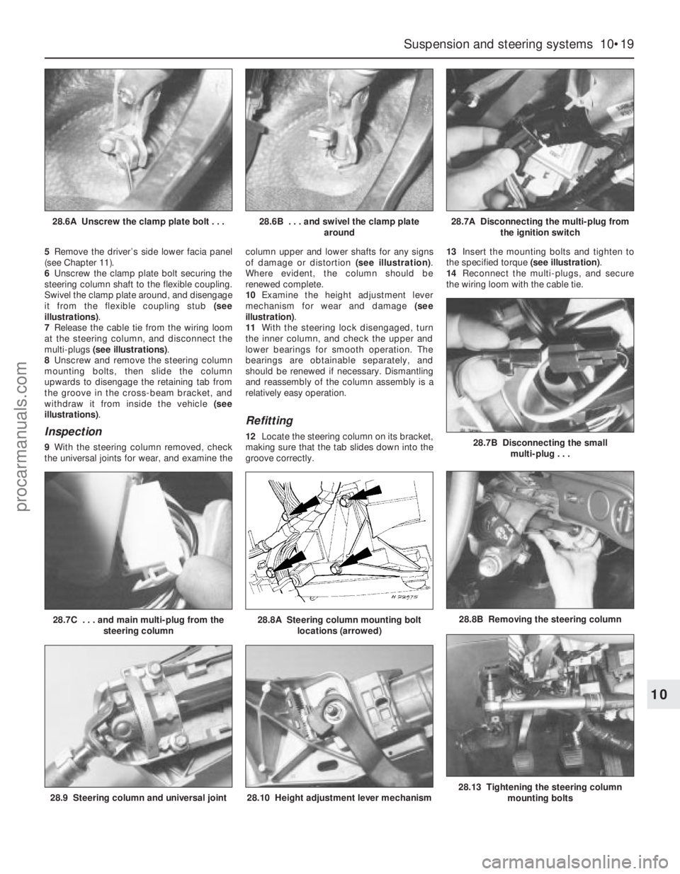
6Unscrew the clamp plate bolt securing the
steering column shaft to the flexible coupling.
Swivel the clamp plate around, and disengage
it from the flexible coupling stub (see
illustrations).
7Release the cable tie from the wiring loom
at the steering column, and disconnect the
multi-plugs (see illustrations).
8Unscrew and remove the steering column
mounting bolts, then slide the column
upwards to disengage the retaining tab from
the groove in the cross-beam bracket, and
withdraw it from inside the vehicle (see
illustrations).
Inspection
9With the steering column removed, check
the universal joints for wear, and examine thecolumn upper and lower shafts for any signs
of damage or distortion (see illustration).
Where evident, the column should be
renewed complete.
10Examine the height adjustment lever
mechanism for wear and damage (see
illustration).
11With the steering lock disengaged, turn
the inner column, and check the upper and
lower bearings for smooth operation. The
bearings are obtainable separately, and
should be renewed if necessary. Dismantling
and reassembly of the column assembly is a
relatively easy operation.
Refitting
12Locate the steering column on its bracket,
making sure that the tab slides down into the
groove correctly.13Insert the mounting bolts and tighten to
the specified torque (see illustration).
14Reconnect the multi-plugs, and secure
the wiring loom with the cable tie.
Suspension and steering systems 10•19
10
28.9 Steering column and universal joint28.10 Height adjustment lever mechanism28.13 Tightening the steering column
mounting bolts
28.7C . . . and main multi-plug from the
steering column28.8A Steering column mounting bolt
locations (arrowed)28.8B Removing the steering column
28.6A Unscrew the clamp plate bolt . . .28.6B . . . and swivel the clamp plate
around28.7A Disconnecting the multi-plug from
the ignition switch
28.7B Disconnecting the small
multi-plug . . .
procarmanuals.com
Page 174 of 279
15Locate the steering column shaft on the
flexible coupling, swivel the clamp plate
round, then insert the bolt and tighten to the
specified torque.
16Refit the driver’s side lower trim panel.
17Refit the steering column upper and lower
shrouds.
18Reconnect the battery negative lead.
Removal
1Disconnect the battery negative (earth) lead
(refer to Chapter 5, Section 1).
2Turn the steering wheel so that the front
wheels are in the straight-ahead position.
Remove the ignition key, then turn the
steering wheel slightly as necessary until the
steering lock engages.
3Unscrew the clamp plate bolt securing the
steering column shaft to the flexible coupling.
Swivel the clamp plate around, and disengage
it from the flexible coupling stub.
4Carefully prise the rubber boot from the
bulkhead, and withdraw it into the passenger
compartment. Take care not to damage the
sealing lip of the boot.
5Using an Allen key, unscrew the clamp bolt
securing the flexible coupling to the pinion
shaft on the steering gear, and withdraw the
coupling from inside the vehicle.
Refitting
6Refitting is a reversal of the removal
procedure, but tighten the clamp bolts to the
specified torque. Make sure that the rubber
boot engages correctly in the bulkhead and
on the flexible coupling.
Removal
1Remove the steering column flexible
coupling as described in Section 29.
2Apply the handbrake, then jack up the frontof the vehicle and support it on axle stands.
Remove both front wheels.
3Working beneath the vehicle, unbolt the
rear engine mounting from the transmission
and underbody.
4Extract the split pins from the track rod end
balljoint nuts, then unscrew the nuts, and
detach the rods from the arms on the steering
knuckles using a conventional balljoint
removal tool. Take care not to damage the
balljoint seals.
5Position a suitable container beneath the
steering gear, then unscrew the union nuts
securing the power steering fluid supply,
return, and cooler lines to the steering gear.
Identify the lines for position, then unbolt the
clamps, disconnect the lines, and allow the
fluid to drain into the container. Cover the
apertures in the steering gear and also the
ends of the fluid pipes, to prevent the ingress
of dust and dirt into the hydraulic circuit.
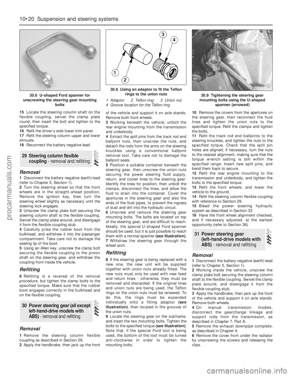
6Unscrew and remove the steering gear
mounting bolts. The bolts are located on top
of the steering gear, and are difficult to reach.
Ideally, the special U-shaped Ford spanner
should be used, but it is just possible to reach
them with a normal spanner (see illustration).
7Withdraw the steering gear through the
wheel arch.
Refitting
8If the steering gear is being replaced with a
new one, the new unit will be supplied
together with union nuts already fitted. The
new nuts must only be used with new feed
and return lines - otherwise, they must be
removed and discarded. If the original lines
and union nuts are being used, the Teflon
rings on the union nuts must be renewed. To
do this, the rings must be expanded
individually onto a fitting adaptor (see
illustration), then located in the grooves of
the union nuts.
9Locate the steering gear on the subframe,
and insert the two mounting bolts. Tighten the
bolts to the specified torque (see illustration).
Note that, if the special Ford tool is being
used, the bottom of the tool must be turned
anti-clockwise in order to tighten the
mounting bolts.10Remove the covers from the apertures on
the steering gear, then reconnect the fluid
lines and tighten the union nuts to the
specified torque. Refit the clamps and tighten
the bolts.
11Refit the track rod end balljoints to the
steering knuckles, and tighten the nuts to the
specified torque. Check that the split pin
holes are aligned; if necessary, turn the nuts
to the nearest alignment, making sure that the
torque wrench setting is still within the
specified range. Insert new split pins, and
bend them back to secure.
12Refit the rear engine mounting to the
transmission and underbody, and tighten the
bolts to the specified torque.
13Refit the front wheels, and lower the
vehicle to the ground.
14Refit the steering column flexible coupling
with reference to Section 29.
15Bleed the power steering hydraulic
system as described in Section 33.
16Have the front wheel alignment checked,
and if necessary adjusted, at the earliest
opportunity (refer to Section 36).Removal
1Disconnect the battery negative (earth) lead
(refer to Chapter 5, Section 1).
2Working inside the vehicle, unscrew the
clamp plate bolt securing the steering column
shaft to the flexible coupling. Swivel the clamp
plate around, and disengage it from the
flexible coupling stub.
3Apply the handbrake, then jack up the front
of the vehicle and support it on axle stands.
Remove both wheels.
4On manual transmission models,
disconnect the gearchange linkage and
support rods from the transmission, as
described in Chapter 7, Part A.
5Remove the exhaust downpipe complete,
as described in Chapter 4.
6Remove the cover from under the radiator
by unscrewing the screws and releasing the
clips.
31 Power steering gear
(left-hand-drive models with
ABS) - removal and refitting
30 Power steering gear (all except
left-hand-drive models with
ABS) - removal and refitting
29 Steering column flexible
coupling - removal and refitting
10•20 Suspension and steering systems
30.6 U-shaped Ford spanner for
unscrewing the steering gear mounting
bolts
30.8 Using an adaptor to fit the Teflon
rings to the union nuts
1 Adaptor 2 Teflon ring 3 Union nut
4 Groove location for the Teflon ring
30.9 Tightening the steering gear
mounting bolts using the U-shaped
spanner (arrowed)
procarmanuals.com
Page 175 of 279
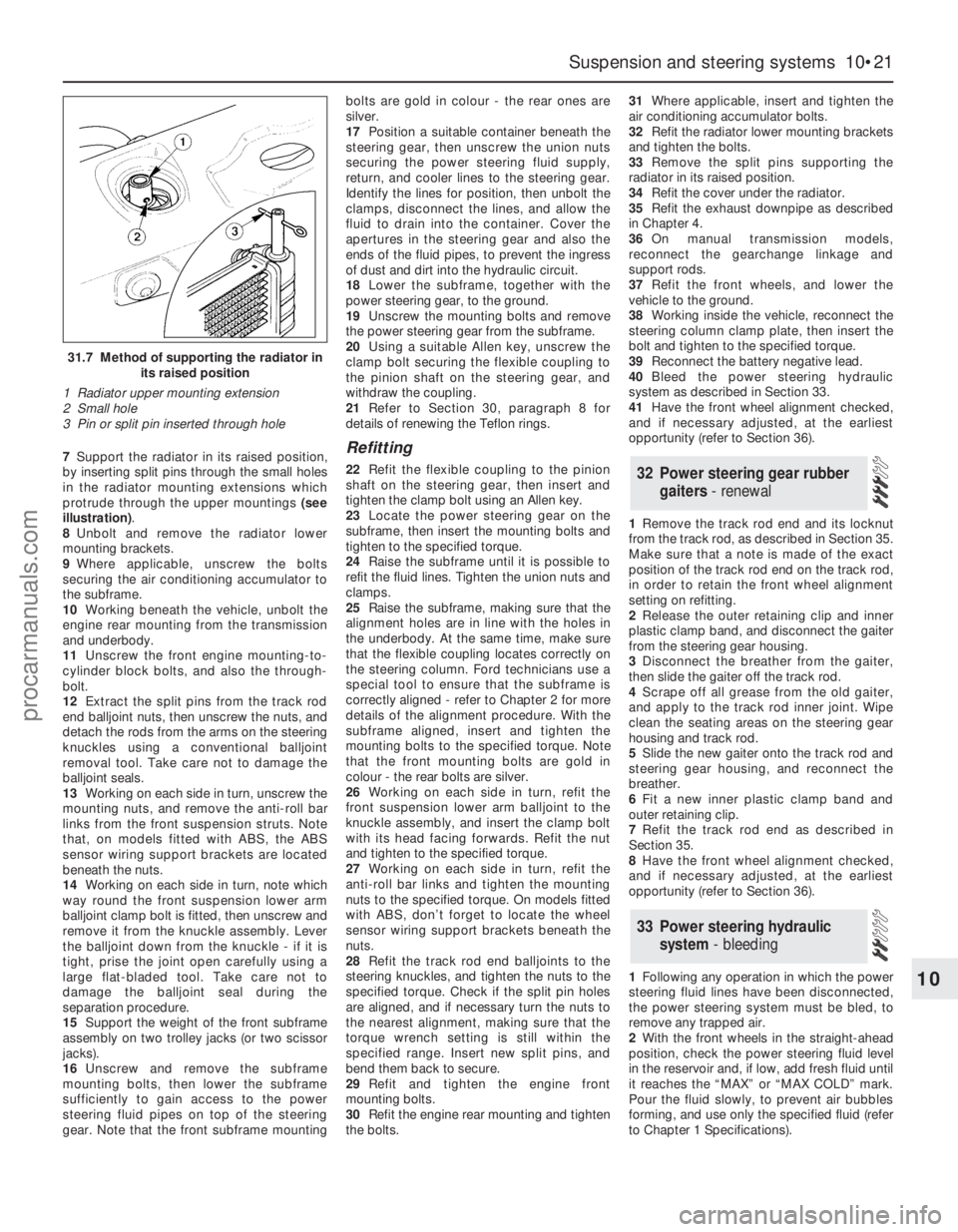
7Support the radiator in its raised position,
by inserting split pins through the small holes
in the radiator mounting extensions which
protrude through the upper mountings (see
illustration).
8Unbolt and remove the radiator lower
mounting brackets.
9Where applicable, unscrew the bolts
securing the air conditioning accumulator to
the subframe.
10Working beneath the vehicle, unbolt the
engine rear mounting from the transmission
and underbody.
11Unscrew the front engine mounting-to-
cylinder block bolts, and also the through-
bolt.
12Extract the split pins from the track rod
end balljoint nuts, then unscrew the nuts, and
detach the rods from the arms on the steering
knuckles using a conventional balljoint
removal tool. Take care not to damage the
balljoint seals.
13Working on each side in turn, unscrew the
mounting nuts, and remove the anti-roll bar
links from the front suspension struts. Note
that, on models fitted with ABS, the ABS
sensor wiring support brackets are located
beneath the nuts.
14Working on each side in turn, note which
way round the front suspension lower arm
balljoint clamp bolt is fitted, then unscrew and
remove it from the knuckle assembly. Lever
the balljoint down from the knuckle - if it is
tight, prise the joint open carefully using a
large flat-bladed tool. Take care not to
damage the balljoint seal during the
separation procedure.
15Support the weight of the front subframe
assembly on two trolley jacks (or two scissor
jacks).
16Unscrew and remove the subframe
mounting bolts, then lower the subframe
sufficiently to gain access to the power
steering fluid pipes on top of the steering
gear. Note that the front subframe mountingbolts are gold in colour - the rear ones are
silver.
17Position a suitable container beneath the
steering gear, then unscrew the union nuts
securing the power steering fluid supply,
return, and cooler lines to the steering gear.
Identify the lines for position, then unbolt the
clamps, disconnect the lines, and allow the
fluid to drain into the container. Cover the
apertures in the steering gear and also the
ends of the fluid pipes, to prevent the ingress
of dust and dirt into the hydraulic circuit.
18Lower the subframe, together with the
power steering gear, to the ground.
19Unscrew the mounting bolts and remove
the power steering gear from the subframe.
20Using a suitable Allen key, unscrew the
clamp bolt securing the flexible coupling to
the pinion shaft on the steering gear, and
withdraw the coupling.
21Refer to Section 30, paragraph 8 for
details of renewing the Teflon rings.Refitting
22Refit the flexible coupling to the pinion
shaft on the steering gear, then insert and
tighten the clamp bolt using an Allen key.
23Locate the power steering gear on the
subframe, then insert the mounting bolts and
tighten to the specified torque.
24Raise the subframe until it is possible to
refit the fluid lines. Tighten the union nuts and
clamps.
25Raise the subframe, making sure that the
alignment holes are in line with the holes in
the underbody. At the same time, make sure
that the flexible coupling locates correctly on
the steering column. Ford technicians use a
special tool to ensure that the subframe is
correctly aligned - refer to Chapter 2 for more
details of the alignment procedure. With the
subframe aligned, insert and tighten the
mounting bolts to the specified torque. Note
that the front mounting bolts are gold in
colour - the rear bolts are silver.
26Working on each side in turn, refit the
front suspension lower arm balljoint to the
knuckle assembly, and insert the clamp bolt
with its head facing forwards. Refit the nut
and tighten to the specified torque.
27Working on each side in turn, refit the
anti-roll bar links and tighten the mounting
nuts to the specified torque. On models fitted
with ABS, don’t forget to locate the wheel
sensor wiring support brackets beneath the
nuts.
28Refit the track rod end balljoints to the
steering knuckles, and tighten the nuts to the
specified torque. Check if the split pin holes
are aligned, and if necessary turn the nuts to
the nearest alignment, making sure that the
torque wrench setting is still within the
specified range. Insert new split pins, and
bend them back to secure.
29Refit and tighten the engine front
mounting bolts.
30Refit the engine rear mounting and tighten
the bolts.31Where applicable, insert and tighten the
air conditioning accumulator bolts.
32Refit the radiator lower mounting brackets
and tighten the bolts.
33Remove the split pins supporting the
radiator in its raised position.
34Refit the cover under the radiator.
35Refit the exhaust downpipe as described
in Chapter 4.
36On manual transmission models,
reconnect the gearchange linkage and
support rods.
37Refit the front wheels, and lower the
vehicle to the ground.
38Working inside the vehicle, reconnect the
steering column clamp plate, then insert the
bolt and tighten to the specified torque.
39Reconnect the battery negative lead.
40Bleed the power steering hydraulic
system as described in Section 33.
41Have the front wheel alignment checked,
and if necessary adjusted, at the earliest
opportunity (refer to Section 36).
1Remove the track rod end and its locknut
from the track rod, as described in Section 35.
Make sure that a note is made of the exact
position of the track rod end on the track rod,
in order to retain the front wheel alignment
setting on refitting.
2Release the outer retaining clip and inner
plastic clamp band, and disconnect the gaiter
from the steering gear housing.
3Disconnect the breather from the gaiter,
then slide the gaiter off the track rod.
4Scrape off all grease from the old gaiter,
and apply to the track rod inner joint. Wipe
clean the seating areas on the steering gear
housing and track rod.
5Slide the new gaiter onto the track rod and
steering gear housing, and reconnect the
breather.
6Fit a new inner plastic clamp band and
outer retaining clip.
7Refit the track rod end as described in
Section 35.
8Have the front wheel alignment checked,
and if necessary adjusted, at the earliest
opportunity (refer to Section 36).
1Following any operation in which the power
steering fluid lines have been disconnected,
the power steering system must be bled, to
remove any trapped air.
2With the front wheels in the straight-ahead
position, check the power steering fluid level
in the reservoir and, if low, add fresh fluid until
it reaches the “MAX” or “MAX COLD” mark.
Pour the fluid slowly, to prevent air bubbles
forming, and use only the specified fluid (refer
to Chapter 1 Specifications).
33 Power steering hydraulic
system - bleeding
32 Power steering gear rubber
gaiters - renewal
Suspension and steering systems 10•21
10
31.7 Method of supporting the radiator in
its raised position
1 Radiator upper mounting extension
2 Small hole
3 Pin or split pin inserted through hole
procarmanuals.com
Page 176 of 279
3Start the engine, and allow it to run at a fast
idle. Check the hoses and connections for
leaks.
4Stop the engine, and recheck the fluid level.
Add more if necessary, up to the “MAX” or
“MAX COLD” mark.
5Start the engine again, allow it to idle, then
bleed the system by slowly turning the
steering wheel from side to side several times.
This should purge the system of all internal
air. However, if air remains in the system
(indicated by the steering operation being very
noisy), leave the vehicle overnight, and repeat
the procedure again the next day.
6If air still remains in the system, it may be
necessary to resort to the Ford method of
bleeding, which uses a vacuum pump. Turn
the steering to the right until it is near the stop,
then fit the vacuum pump to the fluid
reservoir, and apply 0.15 bars of vacuum.
Maintain the vacuum for a minimum of
5 minutes, then repeat the procedure with the
steering turned to the left.
7Keep the fluid level topped-up throughout
the bleeding procedure; note that, as the fluid
temperature increases, the level will rise.
8On completion, switch off the engine, and
return the front wheels to the straight-ahead
position.
Removal
1Disconnect the battery negative (earth) lead
(refer to Chapter 5, Section 1).
2Unscrew and remove the bolt securing the
hydraulic fluid line support to the engine lifting
bracket on the right-hand side of the engine.
3Unscrew and remove the bolt securing the
hydraulic fluid line support to the pump
mounting bracket.
4Position a suitable container beneath the
power steering pump, to catch spilt fluid.
5Loosen the clip, and disconnect the fluid
supply hose from the pump inlet. Plug the
hose, to prevent the ingress of dust and dirt.
6Unscrew the union nut, and disconnect the
high-pressure line from the pump. Allow the
fluid to drain into the container.
7Apply the handbrake, then jack up the front
of the vehicle and support it on axle stands.
Remove the right-hand front wheel.
8Unbolt and remove the lower drivebelt
cover.
9Using a spanner, rotate the drivebelt
tensioner in a clockwise direction to release
the belt tension, then slip the drivebelt off the
pulleys and remove from the vehicle. Refer to
Chapter 1 if necessary.
10Unscrew and remove the four mounting
bolts, and withdraw the power steering pump
from its bracket. Access to the bolts on the
right-hand side of the engine is gained by
turning the pump pulley until a hole lines up
with the bolt.
Refitting
11Locate the power steering pump on the
mounting bracket, and secure with the four
bolts. Tighten the bolts to the specified
torque.
12Slip the drivebelt over the pulleys, then
rotate the drivebelt tensioner in a clockwise
direction, and locate the drivebelt on it.
Release the tensioner to tension the drivebelt.
13Refit the lower belt cover.
14Refit the right-hand front wheel, and lower
the vehicle to the ground.
15If necessary, the sealing ring on the high-
pressure outlet should be renewed, using the
same procedure as described in Section 30,
paragraph 8.
16Reconnect the high-pressure line to the
pump, and tighten the union nut.
17Reconnect the fluid supply hose to the
pump inlet, and tighten the clip.
18Refit the hydraulic fluid line support to the
pump mounting bracket, and tighten the bolt.
19Refit the hydraulic fluid line support to the
engine lifting bracket on the right-hand side of
the engine, and tighten the bolt.
20Reconnect the battery negative lead.
21Bleed the power steering hydraulic
system as described in Section 33.
1Apply the handbrake, then jack up the front
of the vehicle and support it on axle stands.
Remove the appropriate front roadwheel.
2Using a suitable spanner, slacken the
locknut on the track rod by a quarter-turn.
Hold the track rod end stationary with another
spanner engaged with the special flats while
loosening the locknut.
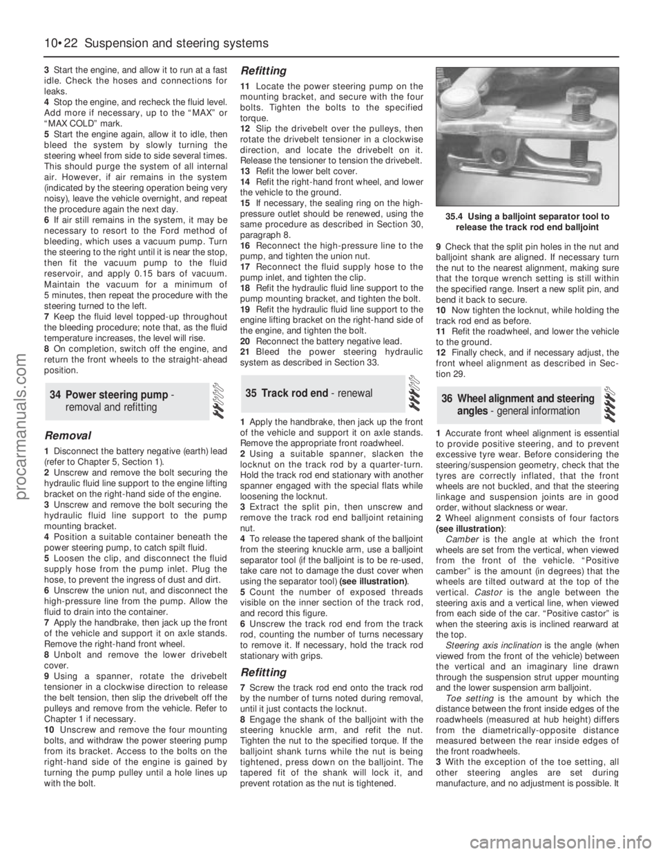
3Extract the split pin, then unscrew and
remove the track rod end balljoint retaining
nut.
4To release the tapered shank of the balljoint
from the steering knuckle arm, use a balljoint
separator tool (if the balljoint is to be re-used,
take care not to damage the dust cover when
using the separator tool) (see illustration).
5Count the number of exposed threads
visible on the inner section of the track rod,
and record this figure.
6Unscrew the track rod end from the track
rod, counting the number of turns necessary
to remove it. If necessary, hold the track rod
stationary with grips.
Refitting
7Screw the track rod end onto the track rod
by the number of turns noted during removal,
until it just contacts the locknut.
8Engage the shank of the balljoint with the
steering knuckle arm, and refit the nut.
Tighten the nut to the specified torque. If the
balljoint shank turns while the nut is being
tightened, press down on the balljoint. The
tapered fit of the shank will lock it, and
prevent rotation as the nut is tightened.9Check that the split pin holes in the nut and
balljoint shank are aligned. If necessary turn
the nut to the nearest alignment, making sure
that the torque wrench setting is still within
the specified range. Insert a new split pin, and
bend it back to secure.
10Now tighten the locknut, while holding the
track rod end as before.
11Refit the roadwheel, and lower the vehicle
to the ground.
12Finally check, and if necessary adjust, the
front wheel alignment as described in Sec-
tion 29.
1Accurate front wheel alignment is essential
to provide positive steering, and to prevent
excessive tyre wear. Before considering the
steering/suspension geometry, check that the
tyres are correctly inflated, that the front
wheels are not buckled, and that the steering
linkage and suspension joints are in good
order, without slackness or wear.
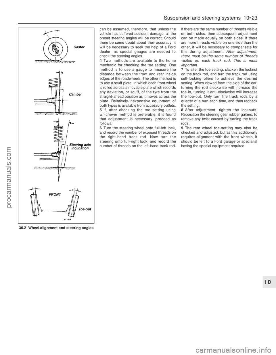
2Wheel alignment consists of four factors
(see illustration):
Camberis the angle at which the front
wheels are set from the vertical, when viewed
from the front of the vehicle. “Positive
camber” is the amount (in degrees) that the
wheels are tilted outward at the top of the
vertical. Castoris the angle between the
steering axis and a vertical line, when viewed
from each side of the car. “Positive castor” is
when the steering axis is inclined rearward at
the top.
Steering axis inclinationis the angle (when
viewed from the front of the vehicle) between
the vertical and an imaginary line drawn
through the suspension strut upper mounting
and the lower suspension arm balljoint.
Toe settingis the amount by which the
distance between the front inside edges of the
roadwheels (measured at hub height) differs
from the diametrically-opposite distance
measured between the rear inside edges of
the front roadwheels.
3With the exception of the toe setting, all
other steering angles are set during
manufacture, and no adjustment is possible. It
36 Wheel alignment and steering
angles - general information35 Track rod end - renewal34 Power steering pump -
removal and refitting
10•22 Suspension and steering systems
35.4 Using a balljoint separator tool to
release the track rod end balljoint
procarmanuals.com
Page 177 of 279
can be assumed, therefore, that unless the
vehicle has suffered accident damage, all the
preset steering angles will be correct. Should
there be some doubt about their accuracy, it
will be necessary to seek the help of a Ford
dealer, as special gauges are needed to
check the steering angles.
4Two methods are available to the home
mechanic for checking the toe setting. One
method is to use a gauge to measure the
distance between the front and rear inside
edges of the roadwheels. The other method is
to use a scuff plate, in which each front wheel
is rolled across a movable plate which records
any deviation, or scuff, of the tyre from the
straight-ahead position as it moves across the
plate. Relatively-inexpensive equipment of
both types is available from accessory outlets.
5If, after checking the toe setting using
whichever method is preferable, it is found
that adjustment is necessary, proceed as
follows.
6Turn the steering wheel onto full-left lock,
and record the number of exposed threads on
the right-hand track rod. Now turn the
steering onto full-right lock, and record the
number of threads on the left-hand track rod.If there are the same number of threads visible
on both sides, then subsequent adjustment
can be made equally on both sides. If there
are more threads visible on one side than the
other, it will be necessary to compensate for
this during adjustment. After adjustment,
there must be the same number of threads
visible on each track rod. This is most
important.
7To alter the toe setting, slacken the locknut
on the track rod, and turn the track rod using
self-locking pliers to achieve the desired
setting. When viewed from the side of the car,
turning the rod clockwise will increase the
toe-in, turning it anti-clockwise will increase
the toe-out. Only turn the track rods by a
quarter of a turn each time, and then recheck
the setting.
8After adjustment, tighten the locknuts.
Reposition the steering gear rubber gaiters, to
remove any twist caused by turning the track
rods.
9The rear wheel toe-setting may also be
checked and adjusted, but as this additionally
requires alignment with the front wheels, it
should be left to a Ford garage or specialist
having the special equipment required.
Suspension and steering systems 10•23
10
36.2 Wheel alignment and steering angles
procarmanuals.com
Page 178 of 279
Chapter 11 Bodywork and fittings
Body side-trim mouldings and adhesive emblems - removal
and refitting . . . . . . . . . . . . . . . . . . . . . . . . . . . . . . . . . . . . . . . . . . 25
Bonnet - removal, refitting and adjustment . . . . . . . . . . . . . . . . . . . . 8
Bonnet lock - removal, refitting and adjustment . . . . . . . . . . . . . . . . 10
Bonnet release cable and lever - removal and refitting . . . . . . . . . . . 9
Boot lid - removal and refitting . . . . . . . . . . . . . . . . . . . . . . . . . . . . . 18
Boot lid lock components - removal and refitting . . . . . . . . . . . . . . . 19
Bumpers - removal and refitting . . . . . . . . . . . . . . . . . . . . . . . . . . . . 6
Central locking system components - testing, removal and refitting . 23
Centre console - removal and refitting . . . . . . . . . . . . . . . . . . . . . . . 30
Door - removal and refitting . . . . . . . . . . . . . . . . . . . . . . . . . . . . . . . 15
Door handle and lock components - removal and refitting . . . . . . . . 14
Door inner trim panel - removal and refitting . . . . . . . . . . . . . . . . . . 11
Door window glass - removal and refitting . . . . . . . . . . . . . . . . . . . . 12
Door window regulator - removal and refitting . . . . . . . . . . . . . . . . . 13
Exterior mirror and glass - removal and refitting . . . . . . . . . . . . . . . . 16
Facia - removal and refitting . . . . . . . . . . . . . . . . . . . . . . . . . . . . . . . 33
General information . . . . . . . . . . . . . . . . . . . . . . . . . . . . . . . . . . . . . . 1Glovebox - removal and refitting . . . . . . . . . . . . . . . . . . . . . . . . . . . . 32
Interior mirror - removal and refitting . . . . . . . . . . . . . . . . . . . . . . . . 17
Interior trim panels - removal and refitting . . . . . . . . . . . . . . . . . . . . 29
Maintenance - bodywork and underframe . . . . . . . . . . . . . . . . . . . . 2
Maintenance - upholstery and carpets . . . . . . . . . . . . . . . . . . . . . . . 3
Major body damage - repair . . . . . . . . . . . . . . . . . . . . . . . . . . . . . . . 5
Minor body damage - repair . . . . . . . . . . . . . . . . . . . . . . . . . . . . . . . 4
Overhead console - removal and refitting . . . . . . . . . . . . . . . . . . . . . 31
Radiator grille - removal and refitting . . . . . . . . . . . . . . . . . . . . . . . . 7
Seat belts - removal and refitting . . . . . . . . . . . . . . . . . . . . . . . . . . . 28
Seats - removal and refitting . . . . . . . . . . . . . . . . . . . . . . . . . . . . . . . 27
Sunroof - general information and adjustment . . . . . . . . . . . . . . . . . 26
Tailgate - removal and refitting . . . . . . . . . . . . . . . . . . . . . . . . . . . . . 20
Tailgate lock components - removal and refitting . . . . . . . . . . . . . . . 22
Tailgate support strut - removal and refitting . . . . . . . . . . . . . . . . . . 21
Wheel arch liner - removal and refitting . . . . . . . . . . . . . . . . . . . . . . 34
Windscreen and fixed windows - removal and refitting . . . . . . . . . . 24
Torque wrench settingsNm lbf ft
Bonnet and tailgate hinges . . . . . . . . . . . . . . . . . . . . . . . . . . . . . . . . . . . 24 18
Boot lid . . . . . . . . . . . . . . . . . . . . . . . . . . . . . . . . . . . . . . . . . . . . . . . . . . 10 7
Front seat mounting bolts . . . . . . . . . . . . . . . . . . . . . . . . . . . . . . . . . . . . 38 28
Seat belt mounting nuts and bolts . . . . . . . . . . . . . . . . . . . . . . . . . . . . . 38 28
Bumper mounting nuts . . . . . . . . . . . . . . . . . . . . . . . . . . . . . . . . . . . . . . 10 7
11•1
Easy,suitable for
novice with little
experienceFairly easy,suitable
for beginner with
some experienceFairly difficult,suitable
for competent DIY
mechanicDifficult,suitable for
experienced DIY
mechanicVery difficult,
suitable for expert DIY
or professional
Degrees of difficulty
Specifications Contents
11
The bodyshell and underframe on all
models is of all-steel welded construction,
incorporating progressive crumple zones at
the front and rear, and a rigid centre safety
cell. The bulkhead behind the engine
compartment incorporates crash grooves
which determine its energy-absorption
characteristics, and special beams to prevent
the intrusion of the front wheels into the
passenger compartment during a serious
accident. All passenger doors incorporate
side impact bars.
All sheet metal surfaces which are prone tocorrosion are galvanized. The painting
process includes a base colour which closely
matches the final topcoat, so that any stone
damage is not noticeable.
Hatchback, Saloon and Estate versions are
available. The front section of the vehicle up to
the “B” pillar is identical on all models.
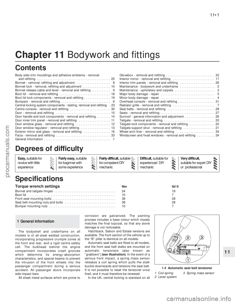
Automatic seat belts are fitted to all models,
and the front seat belt stalks are mounted on
automatic tensioners (also known as
“grabbers”) (see illustration). In the event of a
serious front impact, a spring mass sensor
releases a coil spring which pulls the stalk
buckle downwards and tensions the seat belt.
It is not possible to reset the tensioner once
fired, and it must therefore be renewed.
In the UK, central locking is standard on all
1 General information
1.4 Automatic seat belt tensioner
1 Coil spring 3 Spring mass sensor
2 Lever system
procarmanuals.com
Page 179 of 279
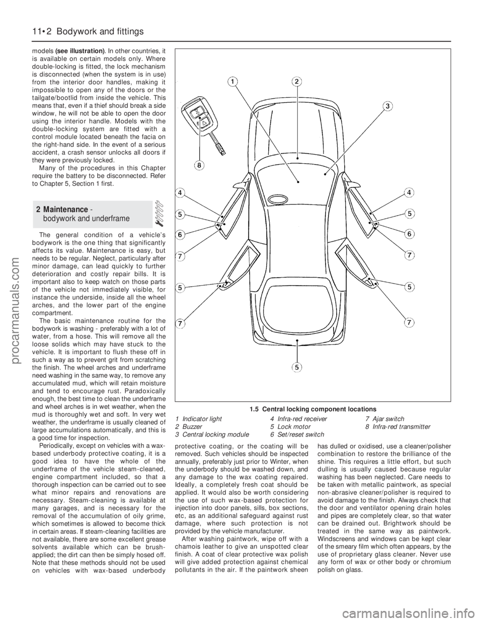
models (see illustration). In other countries, it
is available on certain models only. Where
double-locking is fitted, the lock mechanism
is disconnected (when the system is in use)
from the interior door handles, making it
impossible to open any of the doors or the
tailgate/bootlid from inside the vehicle. This
means that, even if a thief should break a side
window, he will not be able to open the door
using the interior handle. Models with the
double-locking system are fitted with a
control module located beneath the facia on
the right-hand side. In the event of a serious
accident, a crash sensor unlocks all doors if
they were previously locked.
Many of the procedures in this Chapter
require the battery to be disconnected. Refer
to Chapter 5, Section 1 first.
The general condition of a vehicle’s
bodywork is the one thing that significantly
affects its value. Maintenance is easy, but
needs to be regular. Neglect, particularly after
minor damage, can lead quickly to further
deterioration and costly repair bills. It is
important also to keep watch on those parts
of the vehicle not immediately visible, for
instance the underside, inside all the wheel
arches, and the lower part of the engine
compartment.
The basic maintenance routine for the
bodywork is washing - preferably with a lot of
water, from a hose. This will remove all the
loose solids which may have stuck to the
vehicle. It is important to flush these off in
such a way as to prevent grit from scratching
the finish. The wheel arches and underframe
need washing in the same way, to remove any
accumulated mud, which will retain moisture
and tend to encourage rust. Paradoxically
enough, the best time to clean the underframe
and wheel arches is in wet weather, when the
mud is thoroughly wet and soft. In very wet
weather, the underframe is usually cleaned of
large accumulations automatically, and this is
a good time for inspection.
Periodically, except on vehicles with a wax-
based underbody protective coating, it is a
good idea to have the whole of the
underframe of the vehicle steam-cleaned,
engine compartment included, so that a
thorough inspection can be carried out to see
what minor repairs and renovations are
necessary. Steam-cleaning is available at
many garages, and is necessary for the
removal of the accumulation of oily grime,
which sometimes is allowed to become thick
in certain areas. If steam-cleaning facilities are
not available, there are some excellent grease
solvents available which can be brush-
applied; the dirt can then be simply hosed off.
Note that these methods should not be used
on vehicles with wax-based underbodyprotective coating, or the coating will be
removed. Such vehicles should be inspected
annually, preferably just prior to Winter, when
the underbody should be washed down, and
any damage to the wax coating repaired.
Ideally, a completely fresh coat should be
applied. It would also be worth considering
the use of such wax-based protection for
injection into door panels, sills, box sections,
etc, as an additional safeguard against rust
damage, where such protection is not
provided by the vehicle manufacturer.
After washing paintwork, wipe off with a
chamois leather to give an unspotted clear
finish. A coat of clear protective wax polish
will give added protection against chemical
pollutants in the air. If the paintwork sheenhas dulled or oxidised, use a cleaner/polisher
combination to restore the brilliance of the
shine. This requires a little effort, but such
dulling is usually caused because regular
washing has been neglected. Care needs to
be taken with metallic paintwork, as special
non-abrasive cleaner/polisher is required to
avoid damage to the finish. Always check that
the door and ventilator opening drain holes
and pipes are completely clear, so that water
can be drained out. Brightwork should be
treated in the same way as paintwork.
Windscreens and windows can be kept clear
of the smeary film which often appears, by the
use of proprietary glass cleaner. Never use
any form of wax or other body or chromium
polish on glass.
2 Maintenance -
bodywork and underframe
11•2 Bodywork and fittings
1.5 Central locking component locations
1 Indicator light
2 Buzzer
3 Central locking module4 Infra-red receiver
5 Lock motor
6 Set/reset switch7 Ajar switch
8 Infra-red transmitter
procarmanuals.com
Page 180 of 279
Mats and carpets should be brushed or
vacuum-cleaned regularly, to keep them free
of grit. If they are badly stained, remove them
from the vehicle for scrubbing or sponging,
and make quite sure they are dry before
refitting. Seats and interior trim panels can be
kept clean by wiping with a damp cloth. If they
do become stained (which can be more
apparent on light-coloured upholstery), use a
little liquid detergent and a soft nail brush to
scour the grime out of the grain of the
material. Do not forget to keep the headlining
clean in the same way as the upholstery.
When using liquid cleaners inside the vehicle,
do not over-wet the surfaces being cleaned.
Excessive damp could get into the seams and
padded interior, causing stains, offensive
odours or even rot.
Note:For more detailed information about
bodywork repair, Haynes Publishing produce
a book by Lindsay Porter called “The Car
Bodywork Repair Manual”. This incorporates
information on such aspects as rust treatment,
painting and glass-fibre repairs, as well as
details on more ambitious repairs involving
welding and panel beating.
Repairs of minor scratches in
bodywork
If the scratch is very superficial, and does
not penetrate to the metal of the bodywork,
repair is very simple. Lightly rub the area of
the scratch with a paintwork renovator, or a
very fine cutting paste, to remove loose paint
from the scratch, and to clear the surrounding
bodywork of wax polish. Rinse the area with
clean water.
Apply touch-up paint to the scratch using a
fine paint brush; continue to apply fine layers
of paint until the surface of the paint in the
scratch is level with the surrounding
paintwork. Allow the new paint at least two
weeks to harden, then blend it into the
surrounding paintwork by rubbing the scratch
area with a paintwork renovator or a very fine
cutting paste. Finally, apply wax polish.
Where the scratch has penetrated right
through to the metal of the bodywork, causingthe metal to rust, a different repair technique
is required. Remove any loose rust from the
bottom of the scratch with a penknife, then
apply rust-inhibiting paint to prevent the
formation of rust in the future. Using a rubber
or nylon applicator, fill the scratch with
bodystopper paste. If required, this paste can
be mixed with cellulose thinners to provide a
very thin paste which is ideal for filling narrow
scratches. Before the stopper-paste in the
scratch hardens, wrap a piece of smooth
cotton rag around the top of a finger. Dip the
finger in cellulose thinners, and quickly sweep
it across the surface of the stopper-paste in
the scratch; this will ensure that the surface of
the stopper-paste is slightly hollowed. The
scratch can now be painted over as described
earlier in this Section.
Repairs of dents in bodywork
When deep denting of the vehicle’s
bodywork has taken place, the first task is to
pull the dent out, until the affected bodywork
almost attains its original shape. There is little
point in trying to restore the original shape
completely, as the metal in the damaged area
will have stretched on impact, and cannot be
reshaped fully to its original contour. It is
better to bring the level of the dent up to a
point which is about 3 mm below the level of
the surrounding bodywork. In cases where the
dent is very shallow anyway, it is not worth
trying to pull it out at all. If the underside of the
dent is accessible, it can be hammered out
gently from behind, using a mallet with a
wooden or plastic head. Whilst doing this,
hold a suitable block of wood firmly against
the outside of the panel, to absorb the impact
from the hammer blows and thus prevent a
large area of the bodywork from being
“belled-out”.
Should the dent be in a section of the
bodywork which has a double skin, or some
other factor making it inaccessible from
behind, a different technique is called for. Drill
several small holes through the metal inside
the area - particularly in the deeper section.
Then screw long self-tapping screws into the
holes, just sufficiently for them to gain a good
purchase in the metal. Now the dent can be
pulled out by pulling on the protruding heads
of the screws with a pair of pliers.
The next stage of the repair is the removal
of the paint from the damaged area, and from
an inch or so of the surrounding “sound”
bodywork. This is accomplished most easily
by using a wire brush or abrasive pad on a
power drill, although it can be done just as
effectively by hand, using sheets of abrasive
paper. To complete the preparation for filling,
score the surface of the bare metal with a
screwdriver or the tang of a file, or
alternatively, drill small holes in the affected
area. This will provide a really good “key” for
the filler paste.
To complete the repair, see the Section on
filling and respraying.
Repairs of rust holes or gashes in
bodywork
Remove all paint from the affected area,
and from an inch or so of the surrounding
“sound” bodywork, using an abrasive pad or a
wire brush on a power drill. If these are not
available, a few sheets of abrasive paper will
do the job most effectively. With the paint
removed, you will be able to judge the severity
of the corrosion, and therefore decide
whether to renew the whole panel (if this is
possible) or to repair the affected area. New
body panels are not as expensive as most
people think, and it is often quicker and more
satisfactory to fit a new panel than to attempt
to repair large areas of corrosion.
Remove all fittings from the affected area,
except those which will act as a guide to the
original shape of the damaged bodywork (eg
headlight shells etc). Then, using tin snips or a
hacksaw blade, remove all loose metal and any
other metal badly affected by corrosion.
Hammer the edges of the hole inwards, in order
to create a slight depression for the filler paste.
Wire-brush the affected area to remove the
powdery rust from the
surface of the remaining metal. Paint the
affected area with rust-inhibiting paint, if the
back of the rusted area is accessible, treat
this also.
Before filling can take place, it will be
necessary to block the hole in some way. This
can be achieved by the use of aluminium or
plastic mesh, or aluminium tape.
Aluminium or plastic mesh, or glass-fibre
matting, is probably the best material to use
for a large hole. Cut a piece to the
approximate size and shape of the hole to be
filled, then position it in the hole so that its
edges are below the level of the surrounding
bodywork. It can be retained in position by
several blobs of filler paste around its
periphery.
Aluminium tape should be used for small or
very narrow holes. Pull a piece off the roll, trim
it to the approximate size and shape required,
then pull off the backing paper (if used) and
stick the tape over the hole; it can be
overlapped if the thickness of one piece is
insufficient. Burnish down the edges of the
tape with the handle of a screwdriver or
similar, to ensure that the tape is securely
attached to the metal underneath.
Bodywork repairs - filling and
respraying
Before using this Section, see the Sections
on dent, deep scratch, rust holes and gash
repairs.
Many types of bodyfiller are available, but
generally speaking, those proprietary kits
which contain a tin of filler paste and a tube of
resin hardener are best for this type of repair.
A wide, flexible plastic or nylon applicator will
be found invaluable for imparting a smooth
and well-contoured finish to the surface of the
filler.
4 Minor body damage - repair
3 Maintenance -
upholstery and carpets
Bodywork and fittings 11•3
11
If the inside of the vehicle
gets wet accidentally, it is
worthwhile taking some
trouble to dry it out properly,
particularly where carpets are involved.
Do not leave oil or electric heaters
inside the vehicle for this purpose.
procarmanuals.com