instrument panel FORD RANGER 2003 2.G Owners Manual
[x] Cancel search | Manufacturer: FORD, Model Year: 2003, Model line: RANGER, Model: FORD RANGER 2003 2.GPages: 248, PDF Size: 2.53 MB
Page 38 of 248
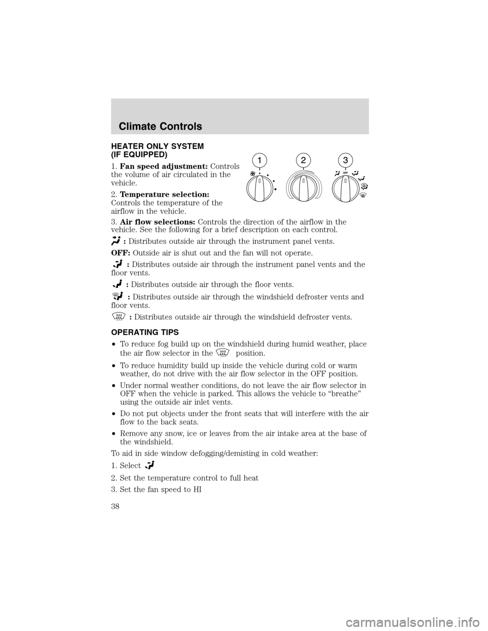
HEATER ONLY SYSTEM
(IF EQUIPPED)
1.Fan speed adjustment:Controls
the volume of air circulated in the
vehicle.
2.Temperature selection:
Controls the temperature of the
airflow in the vehicle.
3.Air flow selections:Controls the direction of the airflow in the
vehicle. See the following for a brief description on each control.
:Distributes outside air through the instrument panel vents.
OFF:Outside air is shut out and the fan will not operate.
:Distributes outside air through the instrument panel vents and the
floor vents.
:Distributes outside air through the floor vents.
:Distributes outside air through the windshield defroster vents and
floor vents.
:Distributes outside air through the windshield defroster vents.
OPERATING TIPS
•To reduce fog build up on the windshield during humid weather, place
the air flow selector in the
position.
•To reduce humidity build up inside the vehicle during cold or warm
weather, do not drive with the air flow selector in the OFF position.
•Under normal weather conditions, do not leave the air flow selector in
OFF when the vehicle is parked. This allows the vehicle to“breathe”
using the outside air inlet vents.
•Do not put objects under the front seats that will interfere with the air
flow to the back seats.
•Remove any snow, ice or leaves from the air intake area at the base of
the windshield.
To aid in side window defogging/demisting in cold weather:
1. Select
2. Set the temperature control to full heat
3. Set the fan speed to HI
Climate Controls
38
Page 39 of 248
4. Direct the outer instrument panel vents towards the side windows
To increase airflow to the outer instrument panel vents, close the vents
located in the middle of the instrument panel.
Do not place objects on top of the instrument panel as these
objects may become projectiles in a collision or sudden stop.
MANUAL HEATING AND AIR
CONDITIONING SYSTEM
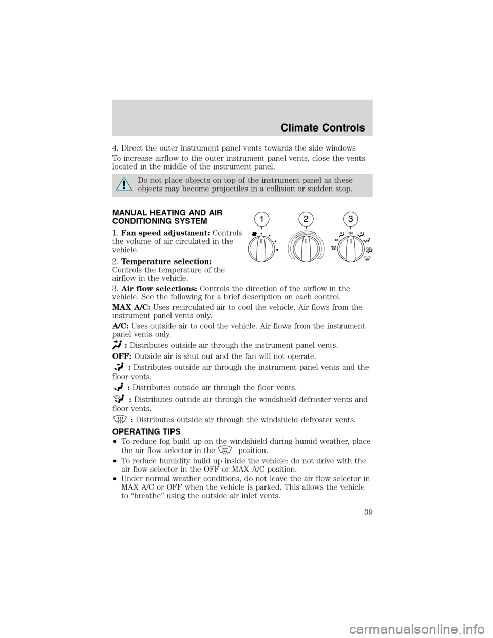
1.Fan speed adjustment:Controls
the volume of air circulated in the
vehicle.
2.Temperature selection:
Controls the temperature of the
airflow in the vehicle.
3.Air flow selections:Controls the direction of the airflow in the
vehicle. See the following for a brief description on each control.
MAX A/C:Uses recirculated air to cool the vehicle. Air flows from the
instrument panel vents only.
A/C:Uses outside air to cool the vehicle. Air flows from the instrument
panel vents only.
:Distributes outside air through the instrument panel vents.
OFF:Outside air is shut out and the fan will not operate.
:Distributes outside air through the instrument panel vents and the
floor vents.
:Distributes outside air through the floor vents.
:Distributes outside air through the windshield defroster vents and
floor vents.
:Distributes outside air through the windshield defroster vents.
OPERATING TIPS
•To reduce fog build up on the windshield during humid weather, place
the air flow selector in the
position.
•To reduce humidity build up inside the vehicle: do not drive with the
air flow selector in the OFF or MAX A/C position.
•Under normal weather conditions, do not leave the air flow selector in
MAX A/C or OFF when the vehicle is parked. This allows the vehicle
to“breathe”using the outside air inlet vents.
Climate Controls
39
Page 40 of 248
•Do not put objects under the front seats that will interfere with the
airflow to the back seats.
•Remove any snow, ice or leaves from the air intake area at the base of
the windshield.
To aid in side window defogging/demisting in cold weather:
1. Select
2. Select A/C
3. Modulate the temperature control to maintain comfort.
4. Set the fan speed to HI
5. Direct the outer instrument panel vents towards the side windows
To increase airflow to the outer instrument panel vents, close the vents
located in the middle of the instrument panel.
Do not place objects on top of the instrument panel as these
objects may become projectiles in a collision or sudden stop.
Climate Controls
40
Page 41 of 248
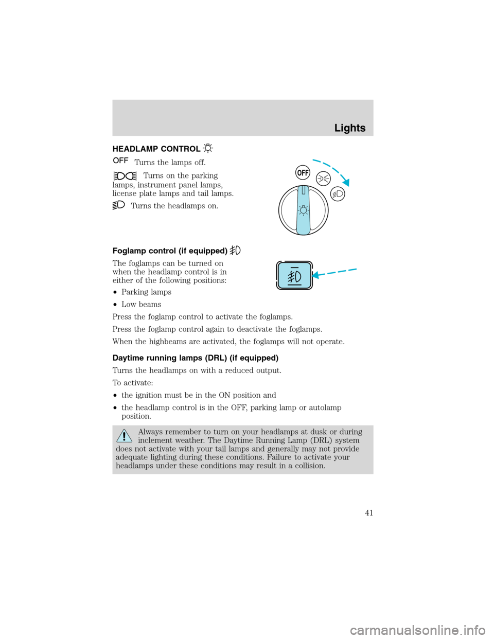
HEADLAMP CONTROL
Turns the lamps off.
Turns on the parking
lamps, instrument panel lamps,
license plate lamps and tail lamps.
Turns the headlamps on.
Foglamp control (if equipped)
The foglamps can be turned on
when the headlamp control is in
either of the following positions:
•Parking lamps
•Low beams
Press the foglamp control to activate the foglamps.
Press the foglamp control again to deactivate the foglamps.
When the highbeams are activated, the foglamps will not operate.
Daytime running lamps (DRL) (if equipped)
Turns the headlamps on with a reduced output.
To activate:
•the ignition must be in the ON position and
•the headlamp control is in the OFF, parking lamp or autolamp
position.
Always remember to turn on your headlamps at dusk or during
inclement weather. The Daytime Running Lamp (DRL) system
does not activate with your tail lamps and generally may not provide
adequate lighting during these conditions. Failure to activate your
headlamps under these conditions may result in a collision.
OFF
Lights
41
Page 42 of 248
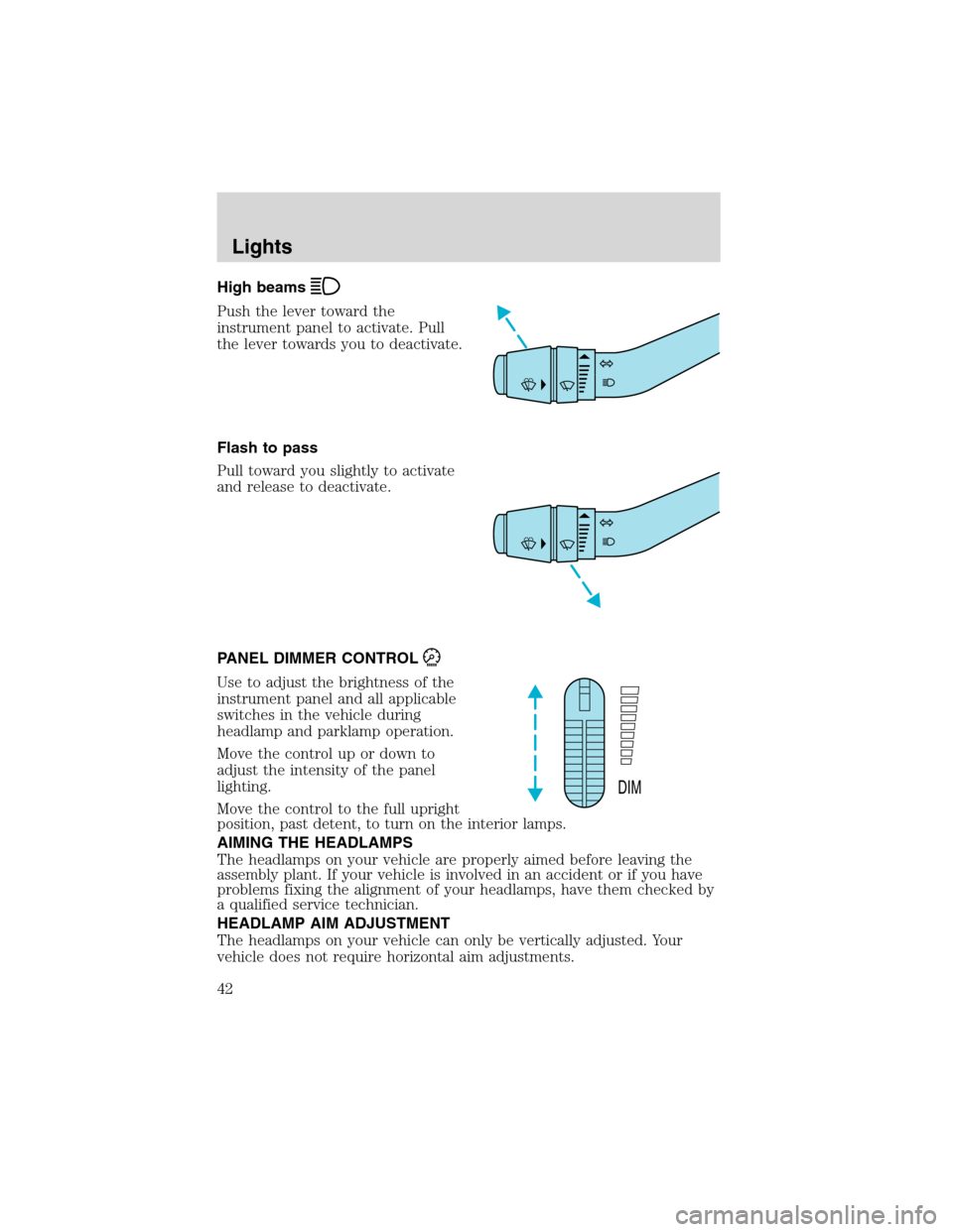
High beams
Push the lever toward the
instrument panel to activate. Pull
the lever towards you to deactivate.
Flash to pass
Pull toward you slightly to activate
and release to deactivate.
PANEL DIMMER CONTROL
Use to adjust the brightness of the
instrument panel and all applicable
switches in the vehicle during
headlamp and parklamp operation.
Move the control up or down to
adjust the intensity of the panel
lighting.
Move the control to the full upright
position, past detent, to turn on the interior lamps.
AIMING THE HEADLAMPS
The headlamps on your vehicle are properly aimed before leaving the
assembly plant. If your vehicle is involved in an accident or if you have
problems fixing the alignment of your headlamps, have them checked by
a qualified service technician.
HEADLAMP AIM ADJUSTMENT
The headlamps on your vehicle can only be vertically adjusted. Your
vehicle does not require horizontal aim adjustments.
DIM
Lights
42
Page 44 of 248
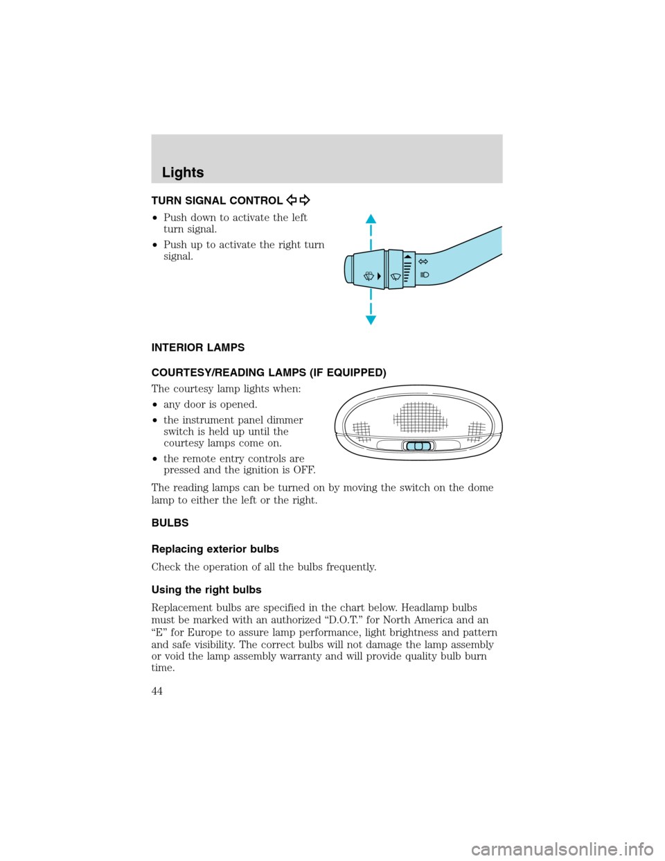
TURN SIGNAL CONTROL
•Push down to activate the left
turn signal.
•Push up to activate the right turn
signal.
INTERIOR LAMPS
COURTESY/READING LAMPS (IF EQUIPPED)
The courtesy lamp lights when:
•any door is opened.
•the instrument panel dimmer
switch is held up until the
courtesy lamps come on.
•the remote entry controls are
pressed and the ignition is OFF.
The reading lamps can be turned on by moving the switch on the dome
lamp to either the left or the right.
BULBS
Replacing exterior bulbs
Check the operation of all the bulbs frequently.
Using the right bulbs
Replacement bulbs are specified in the chart below. Headlamp bulbs
must be marked with an authorized“D.O.T.”for North America and an
“E”for Europe to assure lamp performance, light brightness and pattern
and safe visibility. The correct bulbs will not damage the lamp assembly
or void the lamp assembly warranty and will provide quality bulb burn
time.
Lights
44
Page 45 of 248
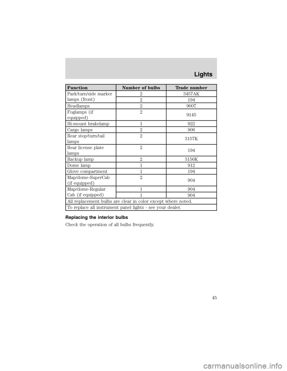
Function Number of bulbs Trade number
Park/turn/side marker
lamps (front)2 3457AK
2 194
Headlamps 2 9007
Foglamps (if
equipped)2
9145
Hi-mount brakelamp 1 922
Cargo lamps 2 906
Rear stop/turn/tail
lamps2
3157K
Rear license plate
lamps2
194
Backup lamp 2 3156K
Dome lamp 1 912
Glove compartment 1 194
Map/dome-SuperCab
(if equipped)2
904
Map/dome-Regular
Cab (if equipped)1 904
1 904
All replacement bulbs are clear in color except where noted.
To replace all instrument panel lights - see your dealer.
Replacing the interior bulbs
Check the operation of all bulbs frequently.
Lights
45
Page 51 of 248
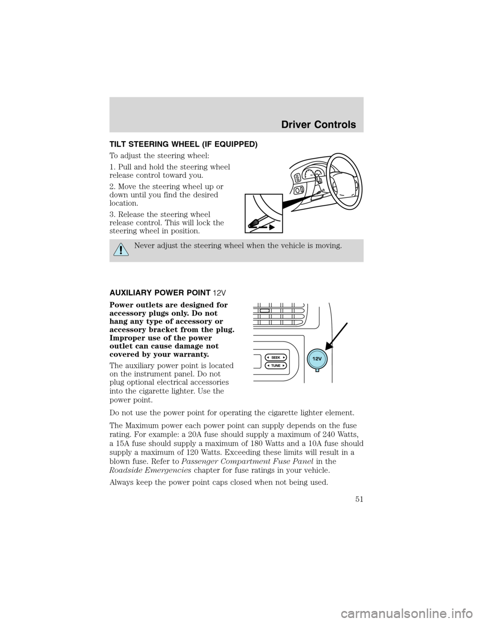
TILT STEERING WHEEL (IF EQUIPPED)
To adjust the steering wheel:
1. Pull and hold the steering wheel
release control toward you.
2. Move the steering wheel up or
down until you find the desired
location.
3. Release the steering wheel
release control. This will lock the
steering wheel in position.
Never adjust the steering wheel when the vehicle is moving.
AUXILIARY POWER POINT
Power outlets are designed for
accessory plugs only. Do not
hang any type of accessory or
accessory bracket from the plug.
Improper use of the power
outlet can cause damage not
covered by your warranty.
The auxiliary power point is located
on the instrument panel. Do not
plug optional electrical accessories
into the cigarette lighter. Use the
power point.
Do not use the power point for operating the cigarette lighter element.
The Maximum power each power point can supply depends on the fuse
rating. For example: a 20A fuse should supply a maximum of 240 Watts,
a 15A fuse should supply a maximum of 180 Watts and a 10A fuse should
supply a maximum of 120 Watts. Exceeding these limits will result in a
blown fuse. Refer toPassenger Compartment Fuse Panelin the
Roadside Emergencieschapter for fuse ratings in your vehicle.
Always keep the power point caps closed when not being used.
Driver Controls
51
Page 149 of 248
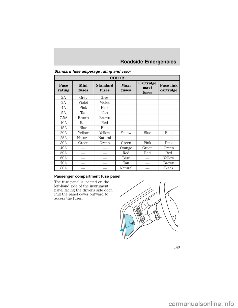
Standard fuse amperage rating and color
COLOR
Fuse
ratingMini
fusesStandard
fusesMaxi
fusesCartridge
maxi
fusesFuse link
cartridge
2A Grey Grey———
3A Violet Violet———
4A Pink Pink———
5A Tan Tan———
7.5A Brown Brown———
10A Red Red———
15A Blue Blue———
20A Yellow Yellow Yellow Blue Blue
25A Natural Natural———
30A Green Green Green Pink Pink
40A——Orange Green Green
50A——Red Red Red
60A——Blue—Yellow
70A——Ta n—Brown
80A——Natural—Black
Passenger compartment fuse panel
The fuse panel is located on the
left-hand side of the instrument
panel facing the driver’s side door.
Pull the panel cover outward to
access the fuses.
Roadside Emergencies
149
Page 151 of 248
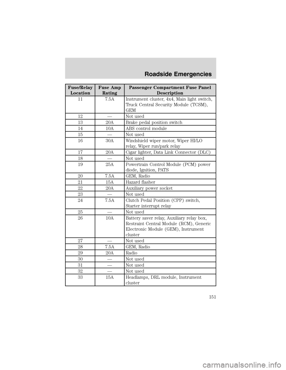
Fuse/Relay
LocationFuse Amp
RatingPassenger Compartment Fuse Panel
Description
11 7.5A Instrument cluster, 4x4, Main light switch,
Truck Central Security Module (TCSM),
GEM
12—Not used
13 20A Brake pedal position switch
14 10A ABS control module
15—Not used
16 30A Windshield wiper motor, Wiper HI/LO
relay, Wiper run/park relay
17 20A Cigar lighter, Data Link Connector (DLC)
18—Not used
19 25A Powertrain Control Module (PCM) power
diode, Ignition, PATS
20 7.5A GEM, Radio
21 15A Hazard flasher
22 20A Auxiliary power socket
23—Not used
24 7.5A Clutch Pedal Position (CPP) switch,
Starter interrupt relay
25—Not used
26 10A Battery saver relay, Auxiliary relay box,
Restraint Central Module (RCM), Generic
Electronic Module (GEM), Instrument
cluster
27—Not used
28 7.5A GEM, Radio
29 20A Radio
30—Not used
31—Not used
32—Not used
33 15A Headlamps, DRL module, Instrument
cluster
Roadside Emergencies
151