FORD SUPER DUTY 2007 1.G Diesel Supplement Manual
Manufacturer: FORD, Model Year: 2007, Model line: SUPER DUTY, Model: FORD SUPER DUTY 2007 1.GPages: 72, PDF Size: 0.61 MB
Page 21 of 72
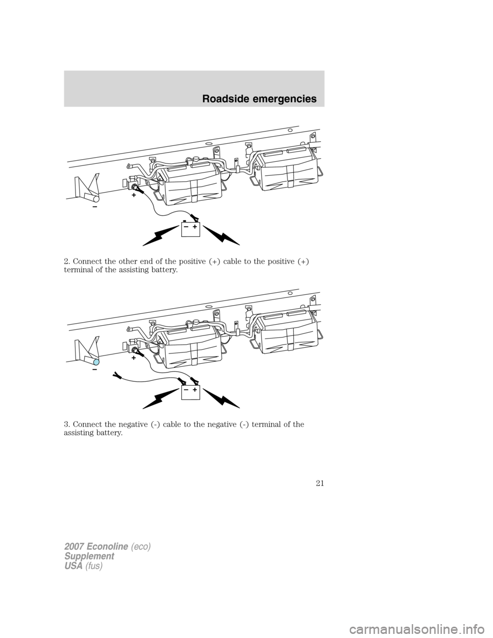
2. Connect the other end of the positive (+) cable to the positive (+)
terminal of the assisting battery.
3. Connect the negative (-) cable to the negative (-) terminal of the
assisting battery.
2007 Econoline(eco)
Supplement
USA(fus)
Roadside emergencies
21
Page 22 of 72
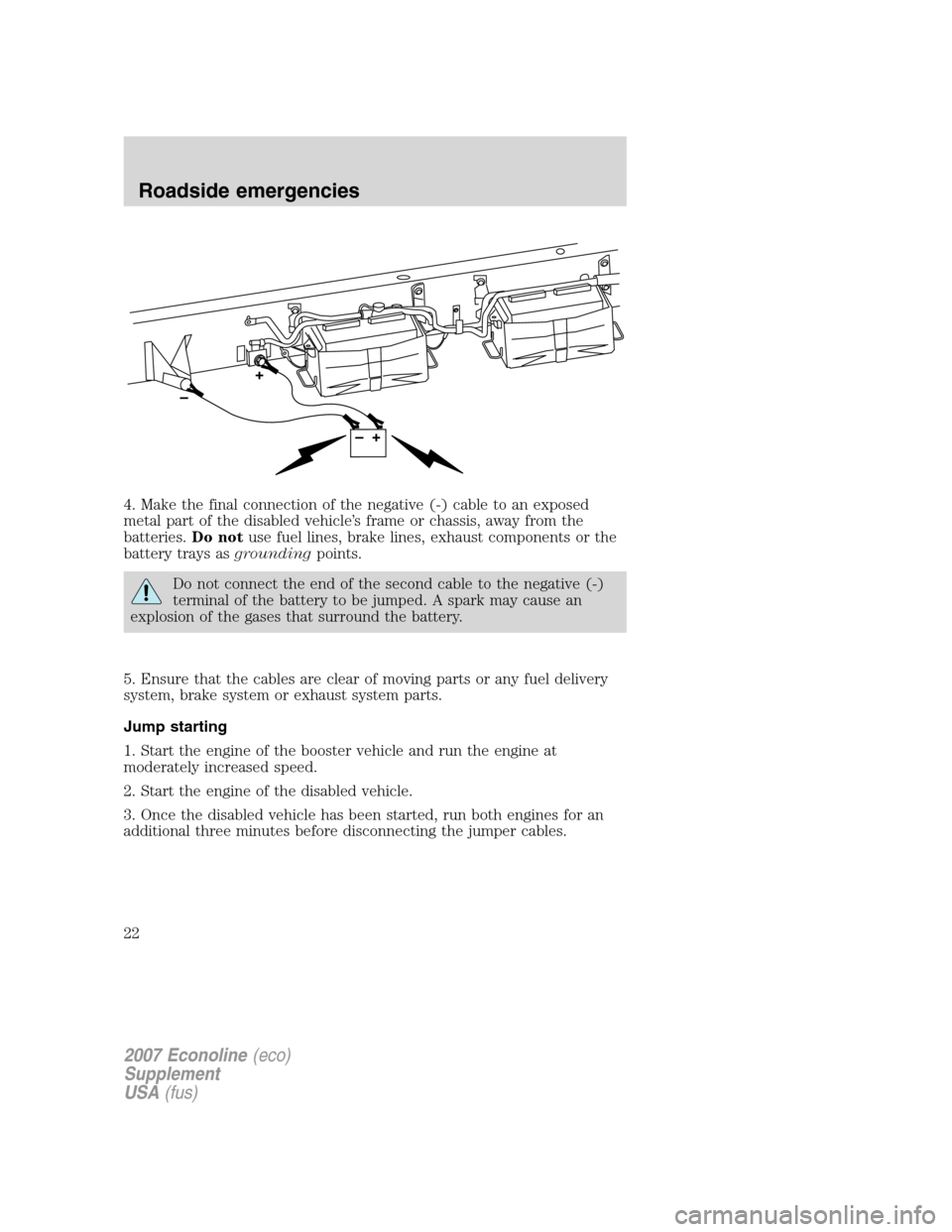
4. Make the final connection of the negative (-) cable to an exposed
metal part of the disabled vehicle’s frame or chassis, away from the
batteries.Do notuse fuel lines, brake lines, exhaust components or the
battery trays asgroundingpoints.
Do not connect the end of the second cable to the negative (-)
terminal of the battery to be jumped. A spark may cause an
explosion of the gases that surround the battery.
5. Ensure that the cables are clear of moving parts or any fuel delivery
system, brake system or exhaust system parts.
Jump starting
1. Start the engine of the booster vehicle and run the engine at
moderately increased speed.
2. Start the engine of the disabled vehicle.
3. Once the disabled vehicle has been started, run both engines for an
additional three minutes before disconnecting the jumper cables.
2007 Econoline(eco)
Supplement
USA(fus)
Roadside emergencies
22
Page 23 of 72
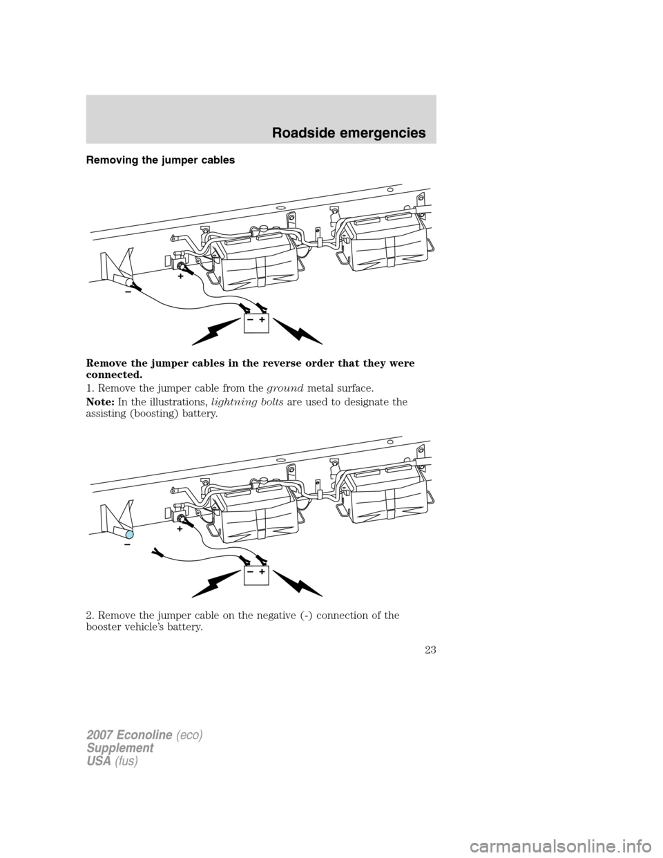
Removing the jumper cables
Remove the jumper cables in the reverse order that they were
connected.
1. Remove the jumper cable from thegroundmetal surface.
Note:In the illustrations,lightning boltsare used to designate the
assisting (boosting) battery.
2. Remove the jumper cable on the negative (-) connection of the
booster vehicle’s battery.
2007 Econoline(eco)
Supplement
USA(fus)
Roadside emergencies
23
Page 24 of 72
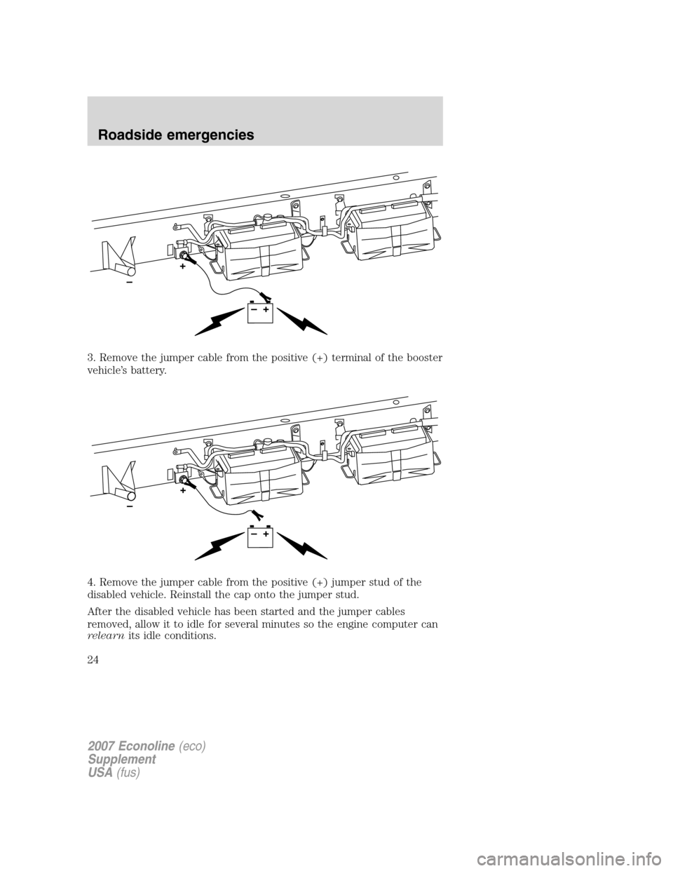
3. Remove the jumper cable from the positive (+) terminal of the booster
vehicle’s battery.
4. Remove the jumper cable from the positive (+) jumper stud of the
disabled vehicle. Reinstall the cap onto the jumper stud.
After the disabled vehicle has been started and the jumper cables
removed, allow it to idle for several minutes so the engine computer can
relearnits idle conditions.
2007 Econoline(eco)
Supplement
USA(fus)
Roadside emergencies
24
Page 25 of 72
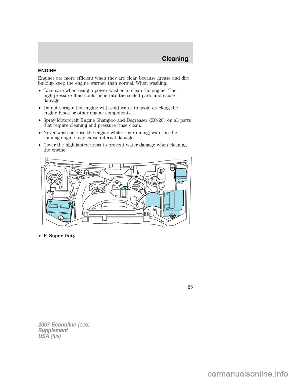
ENGINE
Engines are more efficient when they are clean because grease and dirt
buildup keep the engine warmer than normal. When washing:
•Take care when using a power washer to clean the engine. The
high-pressure fluid could penetrate the sealed parts and cause
damage.
•Do not spray a hot engine with cold water to avoid cracking the
engine block or other engine components.
•Spray Motorcraft Engine Shampoo and Degreaser (ZC-20) on all parts
that require cleaning and pressure rinse clean.
•Never wash or rinse the engine while it is running; water in the
running engine may cause internal damage.
•Cover the highlighted areas to prevent water damage when cleaning
the engine.
•F–Super Duty
2007 Econoline(eco)
Supplement
USA(fus)
Cleaning
25
Page 26 of 72
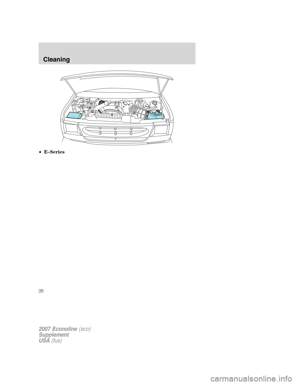
•E–Series
2007 Econoline(eco)
Supplement
USA(fus)
Cleaning
26
Page 27 of 72
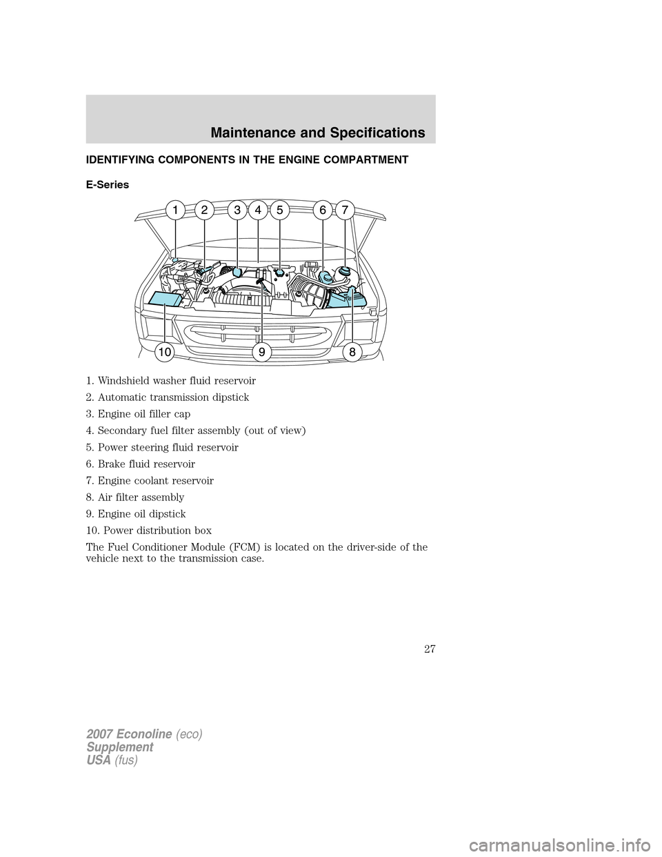
IDENTIFYING COMPONENTS IN THE ENGINE COMPARTMENT
E-Series
1. Windshield washer fluid reservoir
2. Automatic transmission dipstick
3. Engine oil filler cap
4. Secondary fuel filter assembly (out of view)
5. Power steering fluid reservoir
6. Brake fluid reservoir
7. Engine coolant reservoir
8. Air filter assembly
9. Engine oil dipstick
10. Power distribution box
The Fuel Conditioner Module (FCM) is located on the driver-side of the
vehicle next to the transmission case.
2007 Econoline(eco)
Supplement
USA(fus)
Maintenance and Specifications
27
Page 28 of 72
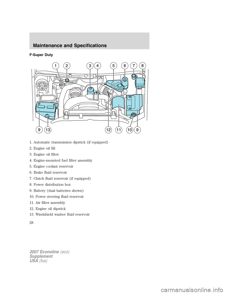
F-Super Duty
1. Automatic transmission dipstick (if equipped)
2. Engine oil fill
3. Engine oil filter
4. Engine-mounted fuel filter assembly
5. Engine coolant reservoir
6. Brake fluid reservoir
7. Clutch fluid reservoir (if equipped)
8. Power distribution box
9. Battery (dual batteries shown)
10. Power steering fluid reservoir
11. Air filter assembly
12. Engine oil dipstick
13. Windshield washer fluid reservoir
2007 Econoline(eco)
Supplement
USA(fus)
Maintenance and Specifications
28
Page 29 of 72
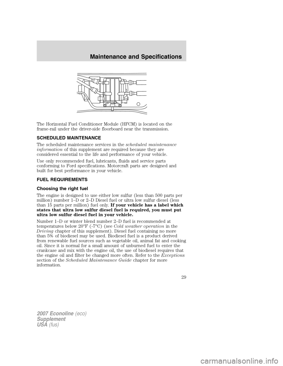
The Horizontal Fuel Conditioner Module (HFCM) is located on the
frame-rail under the driver-side floorboard near the transmission.
SCHEDULED MAINTENANCE
The scheduled maintenance services in thescheduled maintenance
information of this supplement are required because they are
considered essential to the life and performance of your vehicle.
Use only recommended fuel, lubricants, fluids and service parts
conforming to Ford specifications. Motorcraft parts are designed and
built for best performance in your vehicle.
FUEL REQUIREMENTS
Choosing the right fuel
The engine is designed to use either low sulfur (less than 500 parts per
million) number 1–D or 2–D Diesel fuel or ultra low sulfur diesel (less
than 15 parts per million) fuel only. If your vehicle has a label which
states that ultra low sulfur diesel fuel is required, you must put
ultra low sulfur diesel fuel in your vehicle.
Number 1–D or winter blend number 2–D fuel is recommended at
temperatures below 20°F (-7°C) (see Cold weather operationin the
Driving chapter of this supplement). Diesel fuel containing no more
than 5% of biodiesel may be used. Biodiesel fuel is a product derived
from renewable fuel sources such as vegetable oil, animal fat and cooking
oil. Since it is normal for a small amount of unburned fuel to enter the
crankcase and mix with the engine oil, the use of biodiesel requires that
the engine oil and filter be changed more often. Refer to the Exceptions
section of the Scheduled Maintenance Guide chapter for more
information.
2007 Econoline (eco)
Supplement
USA (fus)
Maintenance and Specifications
29
Page 30 of 72
Do not use home heating oil or any diesel fuel not intended for
highway use. Red dye is used to identify fuels intended for
agricultural and non-highway use. Damage to the fuel injection
system, engine and exhaust catalyst can occur if an improper fuel
is used. Do not add gasoline, gasohol or alcohol to diesel fuel.
This practice creates a serious fire hazard and engine
performance problems.
Fuel Filler Cap
When fueling your vehicle:
1. Turn the engine off.
2. Carefully turn the filler cap counterclockwise until it stops.
3. Pull to remove the cap from the fuel filler pipe.
4. To install the cap, align the tabs on the cap with the notches on the
filler pipe.
5. Turn the filler cap clockwise until a few clicks are heard.
If the “Check Fuel Cap” message comes on and stays on after you start
the engine, the fuel filler cap may not be properly installed. Turn off the
engine, remove the fuel filler cap, align the cap properly and reinstall it.
If you must replace the fuel filler cap, replace it with a fuel filler
cap that is designed for your vehicle. The customer warranty may
be void for any damage to the fuel tank or fuel system if the
correct genuine Ford or Motorcraft fuel filler cap is not used.
The fuel system may be under pressure. If the fuel filler cap is
venting vapor or if you hear a hissing sound, wait until it stops
before completely removing the fuel filler cap. Otherwise, fuel may
spray out and injure you or others.
If you do not use the proper fuel filler cap, excessive pressure or
vacuum in the fuel tank may damage the fuel system or cause
the fuel cap to disengage in a collision, which may result in possible
personal injury.
Fuel quality
It should not be necessary to add any aftermarket additives to your fuel
tank if you use a properly formulated diesel fuel that meets the ASTM D
975 industry specification. Aftermarket additives can damage the injector
system or engine. Repairs to correct the effects of using an aftermarket
product in your fuel may not be covered by your warranty.
2007 Econoline (eco)
Supplement
USA (fus)
Maintenance and Specifications
30