power steering GEELY CK 2008 Workshop Manual
[x] Cancel search | Manufacturer: GEELY, Model Year: 2008, Model line: CK, Model: GEELY CK 2008Pages: 392, PDF Size: 38.86 MB
Page 4 of 392
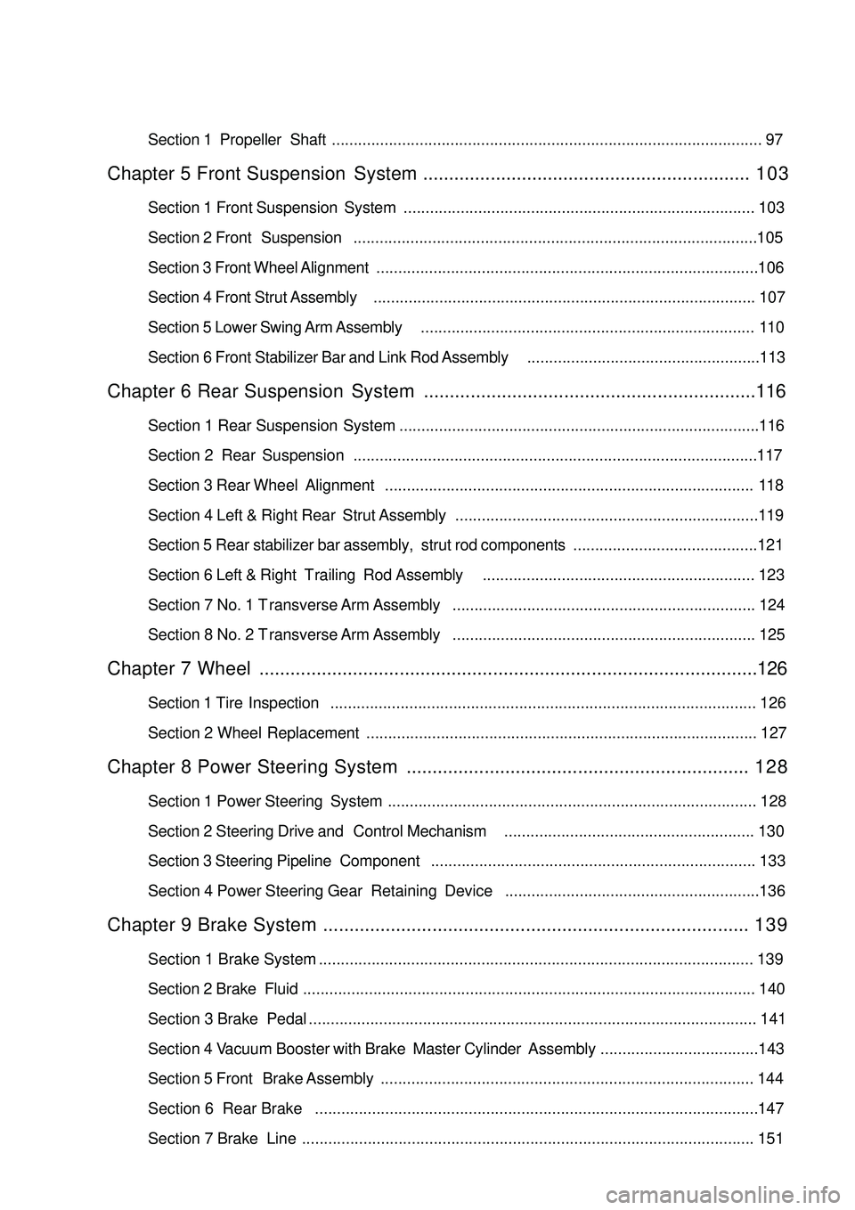
Section 1 Propeller Shaft.................................................................................................. 97Chapter 5 Front Suspension System............................................................... 1 0 3Section 1 Front Suspension System................................................................................ 103
Section 2 Front Suspension............................................................................................105
Section 3 Front Wheel Alignment.......................................................................................106
Section 4 Front Strut Assembly....................................................................................... 107
Section 5 Lower Swing Arm Assembly............................................................................ 110
Section 6 Front Stabilizer Bar and Link Rod Assembly.....................................................113Chapter 6 Rear Suspension System................................................................116Section 1 Rear Suspension System
Section 2 Rear Suspension............................................................................................117
Section 3 Rear Wheel Alignment.................................................................................... 118
Section 4 Left & Right Rear Strut Assembly.....................................................................119
Section 5 Rear stabilizer bar assembly, strut rod components..........................................121
Section 6 Left & Right Trailing Rod Assembly.............................................................. 123
Section 7 No. 1 Transverse Arm Assembly..................................................................... 124
Section 8 No. 2 Transverse Arm Assembly..................................................................... 125Chapter 7 Wheel................................................................................................126Section 1 Tire Inspection................................................................................................. 126
Section 2 Wheel Replacement......................................................................................... 127Chapter 8 Power Steering System.................................................................. 1 2 8Section 1 Power Steering System.................................................................................... 128
Section 2 Steering Drive and Control Mechanism......................................................... 130
Section 3 Steering Pipeline Component.......................................................................... 133
Section 4 Power Steering Gear Retaining DeviceChapter 9 Brake System.................................................................................. 1 3 9Section 1 Brake System ................................................................................................... 139
Section 2 Brake Fluid....................................................................................................... 140
Section 3 Brake Pedal...................................................................................................... 141
Section 4 Vacuum Booster with Brake Master Cylinder Assembly....................................143
Section 5 Front Brake Assembly..................................................................................... 144
Section 6 Rear Brake
Section 7 Brake Line ....................................................................................................... 151..................................................................................116
.....................................................................................................147..........................................................136
Page 8 of 392
1Part I EngineChapter 1 Engine Assembly
(MR479Q, MR479QA, MR481QA)Section 1 Routine Inspection1. Check coolant
2. Check engine oil
3. Check battery
4. Check air cleaner element assembly
5. Check spark plug
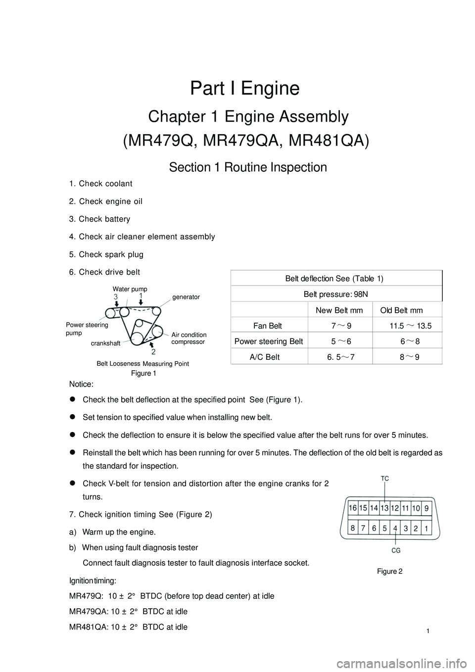
6. Check drive belt
Figure 1
Notice:
�zCheck the belt deflection at the specified point See (Figure 1).
�zSet tension to specified value when installing new belt.
�zCheck the deflection to ensure it is below the specified value after the belt runs for over 5 minutes.
�zReinstall the belt which has been running for over 5 minutes. The deflection of the old belt is regarded as
the standard for inspection.
�zCheck V-belt for tension and distortion after the engine cranks for 2
turns.
7. Check ignition timing See (Figure 2)
a) Warm up the engine.
b) When using fault diagnosis tester
Connect fault diagnosis tester to fault diagnosis interface socket.
Ignition timing:
MR479Q: 10 ± 2° BTDC (before top dead center) at idle
MR479QA: 10 ± 2° BTDC at idle
MR481QA: 10 ± 2° BTDC at idleFigure 2New Belt mm Old Belt mm
Fan Belt 7~
13. 5
Power steering Belt 5~
66~
8
A/C Belt 6. 5
~78~
9 Belt deflection See (Table 1)
Be lt pre ssure : 98NBelt Looseness
Measuring PointWater pump
Power steering
crankshaftgenerator
Air condition
compressor pump11.5~
9
Page 12 of 392

5Section 2 Drive Belt Replacement1. Disconnect all engine pipe hose and wire joint. Remove engine assembly from the engine
compartment, jack up the body, take out the engine assembly slowly (See Provision 20, Section
Two, Chapter Two for detailed information)
2. Remove generator V-belt See (Figure 5)
3. Remove No. 1 V-belt A/C compressor to crankshaft pulley
4. Remove water pump belt See (Figure 6)
5. Install water pump V-belt
6. Adjust V-belt of steering assisting pump
(a) Adjust power steering belt tension, tighten bolt B.
(b) Tighten bolt A.
Torque : 39N. m
7. Install V-belt A/C compressor No. 1 to crankshaft pulley
8. Adjust V-belt A/C compressor No. 1 to crankshaft pulley
(a) Adjust A/C belt tension by tightening bolt B.
(b) Tighten nut A.
Torque : 39N. m
9. Install Generator V-belt See (Figure 7)
10. Adjust Generator V-belt.
Tighten bolt A and then bolt B.
Torque: Bolt A 18N. m Bolt B 58N. m
11. Check driving belt for distortion and tension
Figure 7 Figure 6 Figure 5
Page 18 of 392

11Component 2Figure 21Fan & Generator V-Belt
Vane-Type Pump V-Belt (V/ Power Steering)
V-Belt No.1Right Engine
Mounting InsulatorDoor AssemblySteering Column
AssemblyFront Shaft Hub Left NutLeft Front Speed Sensor Left Engine Mounting Bracket Steering Column Hole CoverHole Cover Steering Column Glove Compartment Front exhauxt pipe assembly
GasketGasket
One-off accessory
Page 20 of 392

13Section 2 Engine Components Replacement1. Avoid gasoline ejection when work.
2. Drain the coolant to empty.
3. Remove air filter assembly with hose. See (Figure 23)
4. Remove battery
5. Remove fuel delivery pipe sub-assembly
6. Disconnect water hoses, disconnect heater outlet hose
from A/C hose.
7. Loose nut, remove accelerator control cable
8. Remove throttle body assembly
9. Remove power steering pump reservoir assembly
10. Remove front exhaust pipe assembly
11. Remove steering gear boot
12. Seperate steering column assembly. See (Figure 24)
13. Remove front wheel hub nut
14. Disconnect front wheel vehicle speed sensor (with ABS)
15. Detach steering tie rod ball stud pin assembly
16. Detach front lower swing arm sub-assembly
17. Detach front propeller assembly. See (Figure 25)
Detach front propeller from the shaft hub with plastic hammer.
18. Disconnect transmission shift cable or gear shift level assembly
19. Disconnect clutch cylinder assembly or disconnect clutch cable
20. Detach engine assembly and transaxle
(a) Hoisting engine ;
(b) Remove 3 bolts. Detach the right engine mounting bracket. See (Figure 26) ;
(c) Remove 1 bolt. Detach the left engine mounting bracket;
(d) Remove 1 bolt. Detach the rear engine mounting bracket;
(e) Remove engine and transaxle and put them on the pallet;
(f) Jack up the boday.Figure 23
Figure 24
Figure 25 Figure 26
Page 21 of 392
1421. Remove radiator assembly
22. Remove engine V-belt
23. Remove No. 1 V- belt (A/C compressor to crankshaft pulley)
24. Remove generator assembly
25. Remove A/C compressor
26. Remove compressor installing No. 1 bracket. Remove 4 bolts and compressor installing No.
1 bracket.
27. Remove starter assembly
28. Remove power steering pump V- belt
29. Detach power steering pump assembly
30. Remove power steering pump, adjust the bracket
31. Detach manual transaxle assembly (Separate automatic transaxle assembly)
32. Detach clutch cover panel assembly.
33. Detach clutch pressure plate assembly.
34. Detach flywheel sub-assembly.
35. Remove engine rear end cover.
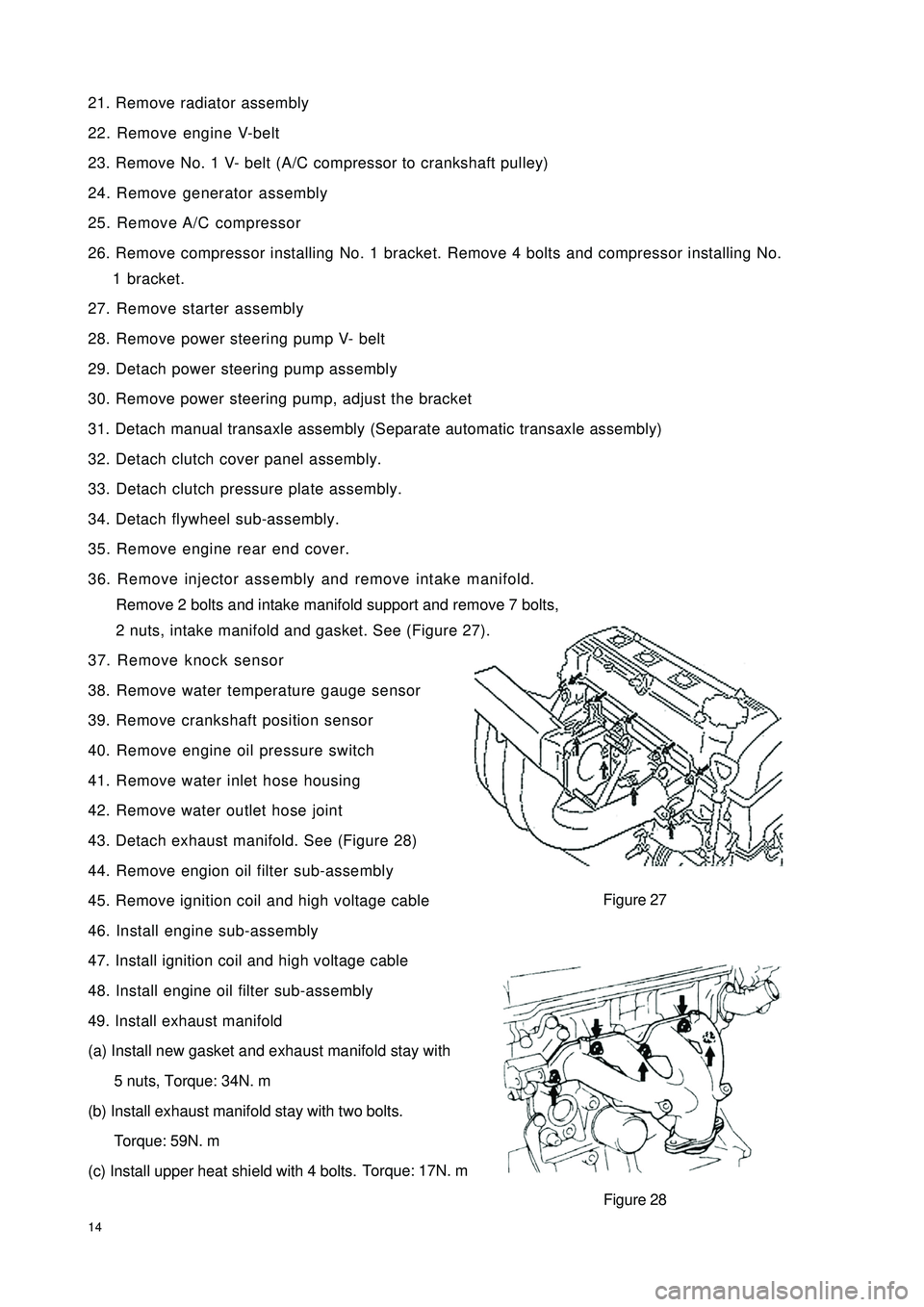
36. Remove injector assembly and remove intake manifold.
Remove 2 bolts and intake manifold support and remove 7 bolts,
2 nuts, intake manifold and gasket. See (Figure 27).
37. Remove knock sensor
38. Remove water temperature gauge sensor
39. Remove crankshaft position sensor
40. Remove engine oil pressure switch
41. Remove water inlet hose housing
42. Remove water outlet hose joint
43. Detach exhaust manifold. See (Figure 28)
44. Remove engion oil filter sub-assembly
45. Remove ignition coil and high voltage cable
46. Install engine sub-assembly
47. Install ignition coil and high voltage cable
48. Install engine oil filter sub-assembly
49. Install exhaust manifold
(a) Install new gasket and exhaust manifold stay with
5 nuts, Torque: 34N. m
(b) Install exhaust manifold stay with two bolts.
Torque: 59N. m
(c) Install upper heat shield with 4 bolts.Torque: 17N. mFigure 27
Figure 28
Page 23 of 392
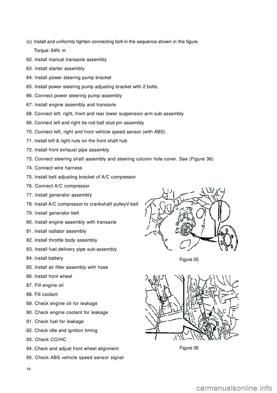
16(c) Install and uniformly tighten connecting bolt in the sequence shown inthe figure.
Torque: 64N. m
62. Install manual transaxle assembly
63. Install starter assembly
64. Install power steering pump bracket
65. Install power steering pump adjusting bracket with 2 bolts.
66. Connect power steering pump assembly
67. Install engine assembly and transaxle
68. Connect left, right, front and rear lower suspension arm sub-assembly
69. Connect left and right tie rod ball stud pin assembly
70. Connect left, right and front vehicle speed sensor (with ABS)
71. Install left & right nuts on the front shaft hub
72. Install front exhaust pipe assembly
73. Connect steering shaft assembly and steering column hole cover. See (Figure 36)
74. Connect wire harness
75. Install belt adjusting bracket of A/C compressor
76. Connect A/C compressor
77. Install generator assembly
78. Install A/C compressor to crankshaft pulleyV-belt
79. Install generator belt
80. Install engine assembly with transaxle
81. Install radiator assembly
82. Install throttle body assembly
83. Install fuel delivery pipe sub-assembly
84. Install battery
85. Install air filter assembly with hose
86. Install front wheel
87. Fill engine oil
88. Fill coolant
89. Check engine oil for leakage
90. Check engine coolant for leakage
91. Check fuel for leakage
92. Check idle and ignition timing
93. Check CO/HC
94. Check and adjust front wheel alignment
95. Check ABS vehicle speed sensor signalFigure 35
Figure 36
Page 24 of 392

17Section 3 Timing Belt ReplacementFigure 37Air Filter Assembly W/ HoseHigh Pressure CableVentilation PipeSeal
Cylinder Head
Right Engine Mounting
Fan & Generator V-Belt
V-Belt No.1Cylinder Head GasketGasket
Timing Chain Or Timing Belt Cover Assembly No. 2
Crankshaft Or Pulley
Cover Sub-Assembly
Crankshaft PulleyTiming Belt Guide
Timing Chain Timing Belt
Cover Sub-Assembly
Generator Assembly Timing Belt
Fan Pulley Vane-Type Pump V-Belt V/ Power Steering
Page 25 of 392

181. Disconnect engine from all the wire harnesses and cables connected to body.
2. Remove air filter assembly with hose. See (Figure 38)
3. Disconnect oil pipe and water hoses
4. Loose positive and negative cables on battery
5. Detach propeller shaft
6. Loose engine left & right rear brackets after hoisting engine
7. Disconnect all the connectors of engine and the body
8. Remove engine per "Provision 20, Section 2, Chapter 2"
9. Remove A/C compressor to crankshaft pulley V-belt
10. Remove power steering pump V-belt
11. Remove water pump fan pulley
12. Remove high pressure cable.
13. Remove cylinder head cover sub-assembly
14. Remove generator assembly. See (Figure 39)
15. Put the piston in Cylinder 1 to TDC compression position
(a)Turn crankshaft pulley to align its notch to the timing mark "0"
on the timing belt cover. See (Figure 40).
(b) Check if the "K" mark on camshaft timing pulley and the timing mark
on the bearing cap are aligned. Crank the crankshaft for 360 degrees
if not. See (Figure 41).
16. Remove crankshaft pulley
17. Remove timing belt cover
18. Remove crankshaft gear or pulley cover sub-assembly
19. Remove timing belt cover sub-assembly
Figure 40 Figure 39 Figure 38
Figure 41
Page 27 of 392
20(c) Check timing belt for deflection
Check the belt distorn as shown in the figure.
Belt deflection:
20N: 5~6mm
Re-adjust the idler if the deflection does not comply with the regulation.
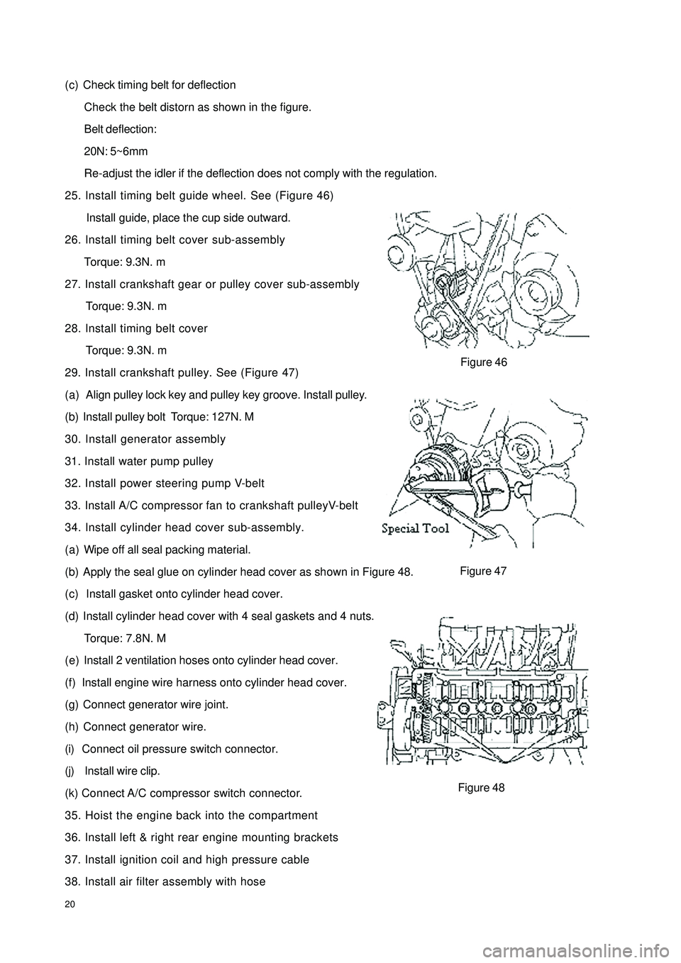
25. Install timing belt guide wheel. See (Figure 46)
Install guide, place the cup side outward.
26. Install timing belt cover sub-assembly
Torque: 9.3N. m
27. Install crankshaft gear or pulley cover sub-assembly
Torque: 9.3N. m
28. Install timing belt cover
Torque: 9.3N. m
29. Install crankshaft pulley. See (Figure 47)
(a) Align pulley lock key and pulley key groove. Install pulley.
(b) Install pulley bolt Torque: 127N. M
30. Install generator assembly
31. Install water pump pulley
32. Install power steering pump V-belt
33. Install A/C compressor fan to crankshaft pulleyV-belt
34. Install cylinder head cover sub-assembly.
(a) Wipe off all seal packing material.
(b) Apply the seal glue on cylinder head cover as shown in Figure 48.
(c) Install gasket onto cylinder head cover.
(d) Install cylinder head cover with 4 seal gaskets and 4 nuts.
Torque: 7.8N. M
(e) Install 2 ventilation hoses onto cylinder head cover.
(f) Install engine wire harness onto cylinder head cover.
(g) Connect generator wire joint.
(h) Connect generator wire.
(i) Connect oil pressure switch connector.
(j) Install wire clip.
(k) Connect A/C compressor switch connector.
35. Hoist the engine back into the compartment
36. Install left & right rear engine mounting brackets
37. Install ignition coil and high pressure cable
38. Install air filter assembly with hoseFigure 48Figure 46
Figure 47