GREAT WALL HOVER 2006 Service Repair Manual
Manufacturer: GREAT WALL, Model Year: 2006, Model line: HOVER, Model: GREAT WALL HOVER 2006Pages: 425, PDF Size: 26.05 MB
Page 181 of 425
special tools
diagram of special tools
grease
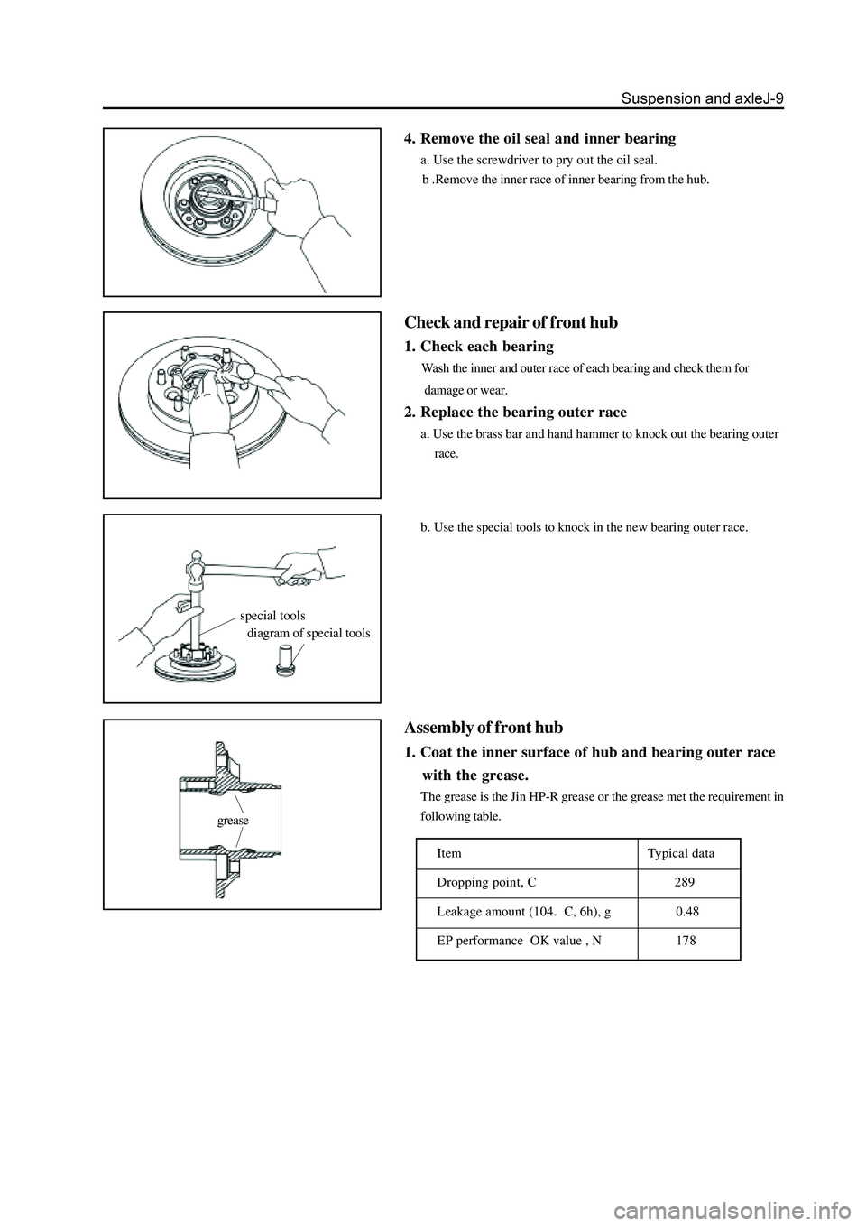
4. Remove the oil seal and inner bearing
a. Use the screwdriver to pry out the oil seal.
b .Remove the inner race of inner bearing from the hub.
Check and repair of front hub
1. Check each bearing
Wash the inner and outer race of each bearing and check them for
damage or wear.
2. Replace the bearing outer race
a. Use the brass bar and hand hammer to knock out the bearing outer
race.
b. Use the special tools to knock in the new bearing outer race.
Assembly of front hub
1. Coat the inner surface of hub and bearing outer race
with the grease.
The grease is the Jin HP-R grease or the grease met the requirement in
following table.
Item Typical data
Dropping point, C
289
Leakage amount (104
C, 6h), g 0.48
EP performance OK value , N
178
Page 182 of 425
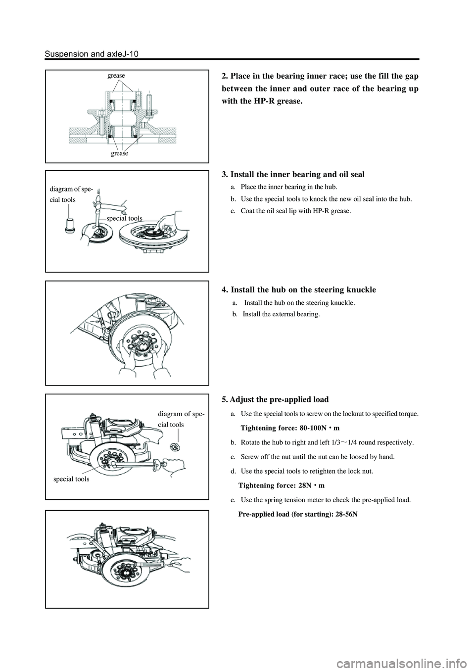
2. Place in the bearing inner race; use the fill the gap
between the inner and outer race of the bearing up
with the HP-R grease.grease
grease
3. Install the inner bearing and oil seal
a. Place the inner bearing in the hub.
b. Use the special tools to knock the new oil seal into the hub.
c. Coat the oil seal lip with HP-R grease.
4. Install the hub on the steering knuckle
a. Install the hub on the steering knuckle.
b. Install the external bearing.
diagram of spe-
cial tools
special tools
5. Adjust the pre-applied load
a. Use the special tools to screw on the locknut to specified torque.
Tightening force: 80-100N
m
b. Rotate the hub to right and left 1/3
1/4 round respectively.
c. Screw off the nut until the nut can be loosed by hand.
d. Use the special tools to retighten the lock nut.
Tightening force: 28N
m
e. Use the spring tension meter to check the pre-applied load.
Pre-applied load (for starting): 28-56N
diagram of spe-
cial tools
special tools
Page 183 of 425
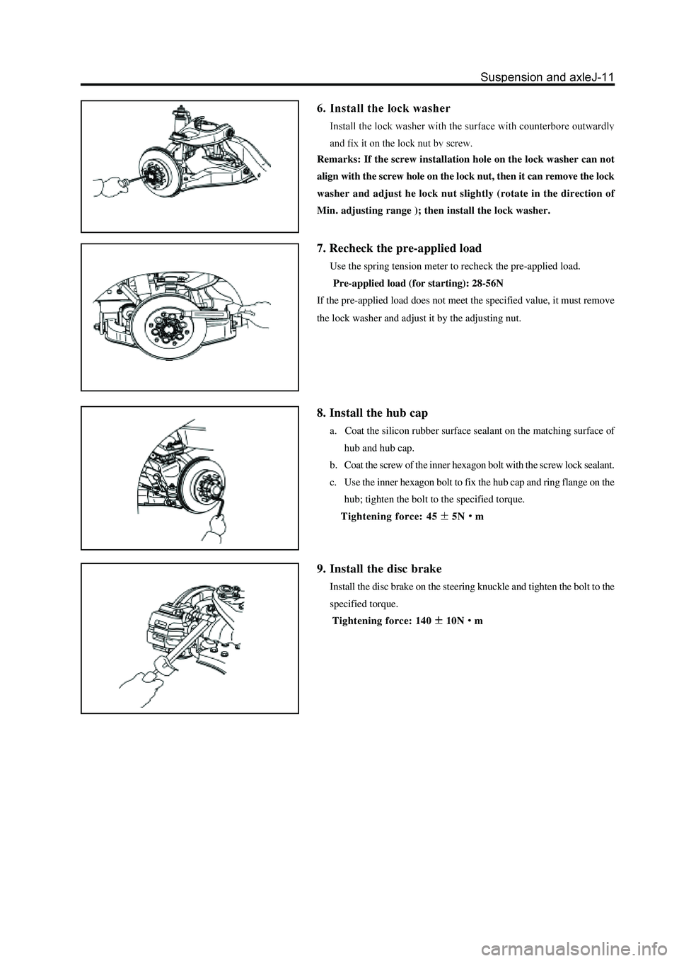
Remarks: If the screw installation hole on the lock washer can not
align with the screw hole on the lock nut, then it can remove the lock
washer and adjust he lock nut slightly (rotate in the direction of
Min. adjusting range ); then install the lock washer.
7. Recheck the pre-applied load
Use the spring tension meter to recheck the pre-applied load.
Pre-applied load (for starting): 28-56N
If the pre-applied load does not meet the specified value, it must remove
the lock washer and adjust it by the adjusting nut.
8. Install the hub cap
a. Coat the silicon rubber surface sealant on the matching surface of
hub and hub cap.
b. Coat the screw of the inner hexagon bolt with the screw lock sealant.
c. Use the inner hexagon bolt to fix the hub cap and ring flange on the
hub; tighten the bolt to the specified torque.
Tightening force: 45
5Nm
9. Install the disc brake
Install the disc brake on the steering knuckle and tighten the bolt to the
specified torque.
Tightening force: 140
10Nm
Page 184 of 425
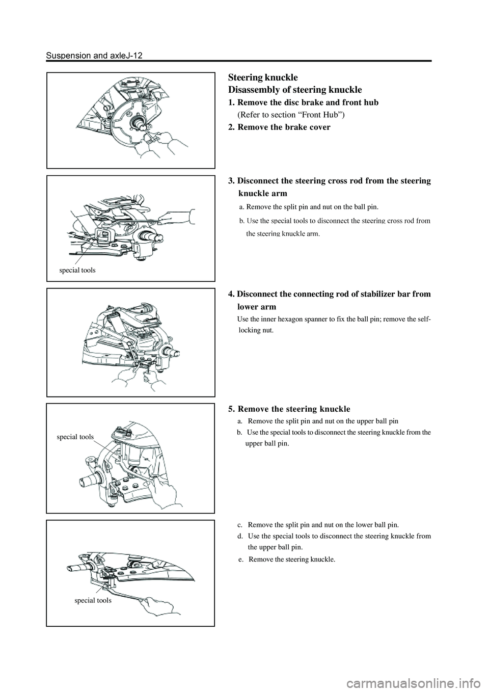
Steering knuckle
Disassembly of steering knuckle
1. Remove the disc brake and front hub
(Refer to section “Front Hub”)
2. Remove the brake cover
special tools
special tools
special tools
3. Disconnect the steering cross rod from the steering
knuckle arm
a. Remove the split pin and nut on the ball pin.
4. Disconnect the connecting rod of stabilizer bar from
lower arm
Use the inner hexagon spanner to fix the ball pin; remove the self-
locking nut.
5. Remove the steering knuckle
a. Remove the split pin and nut on the upper ball pin
b. Use the special tools to disconnect the steering knuckle from the
upper ball pin.
c. Remove the split pin and nut on the lower ball pin.
d. Use the special tools to disconnect the steering knuckle from
the upper ball pin.
e. Remove the steering knuckle.
Page 185 of 425
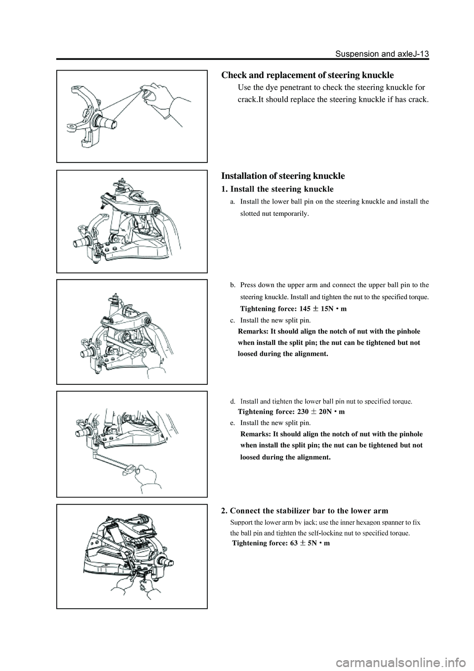
Check and replacement of steering knuckle
Use the dye penetrant to check the steering knuckle for
crack.It should replace the steering knuckle if has crack.
Installation of steering knuckle
1. Install the steering knuckle
a. Install the lower ball pin on the steering knuckle and install the
slotted nut temporarily.
b. Press down the upper arm and connect the upper ball pin to the
steering knuckle. Install and tighten the nut to the specified torque.
Tightening force: 145
15Nm
c. Install the new split pin.
Remarks: It should align the notch of nut with the pinhole
when install the split pin; the nut can be tightened but not
loosed during the alignment.
Tightening force: 23020Nm
e. Install the new split pin.
Remarks: It should align the notch of nut with the pinhole
when install the split pin; the nut can be tightened but not
loosed during the alignment.
Tightening force: 635Nm
Page 186 of 425
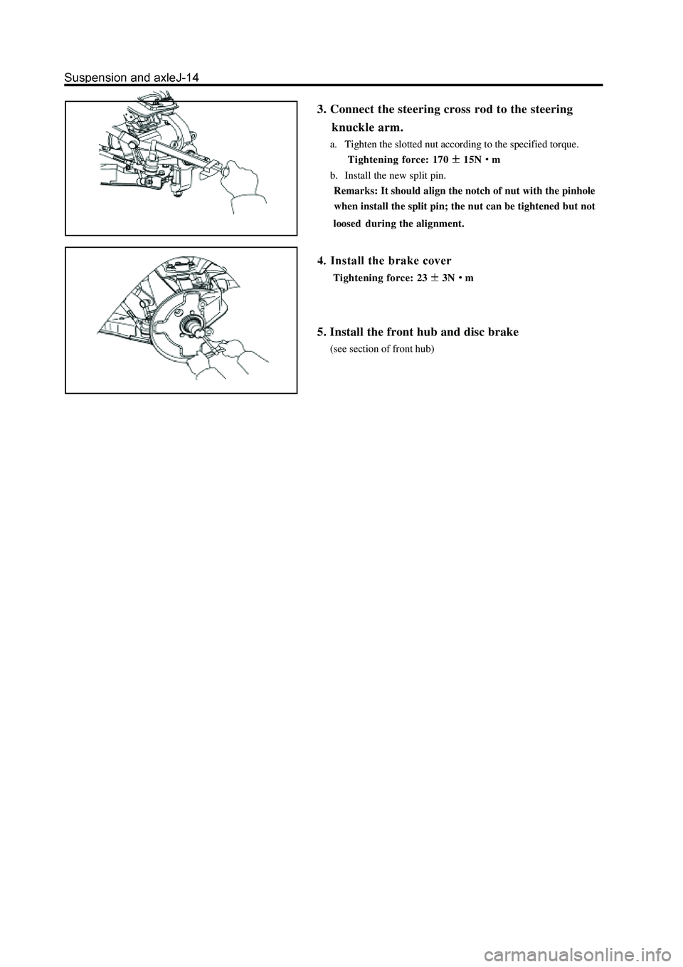
3. Connect the steering cross rod to the steering
knuckle arm.
a. Tighten the slotted nut according to the specified torque.
Tightening force: 170
15Nm
b. Install the new split pin.
Remarks: It should align the notch of nut with the pinhole
when install the split pin; the nut can be tightened but not
loosedduring the alignment.
Tightening force: 233Nm
5. Install the front hub and disc brake
(see section of front hub)
Page 187 of 425
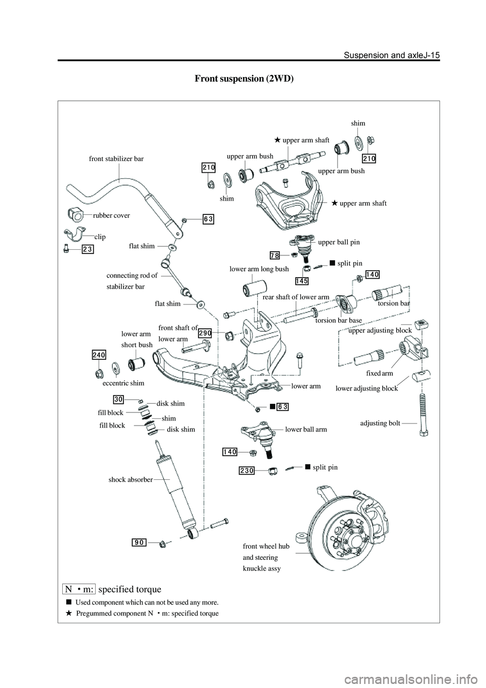
Front suspension (2WD)
front stabilizer bar
rubber cover
clip
connecting rod of
stabilizer bar
flat shim
front shaft of
lower arm
split pin
adjusting bolt
lower adjusting block
fixed arm
upper adjusting block
lower arm
rear shaft of lower arm
torsion bar base
torsion bar
lower arm long bushsplit pin
upper ball pin
upper arm shaft
upper arm bush
flat shim
lower arm
short bush
eccentric shim
disk shim
fill block
fill block
disk shim shim
shock absorbershimshim
upper arm bush
upper arm shaft
lower ball arm
front wheel hub
and steering
knuckle assy
N m: specified torque
Used component which can not be used any more.
Pregummed component N m: specified torque
Page 188 of 425
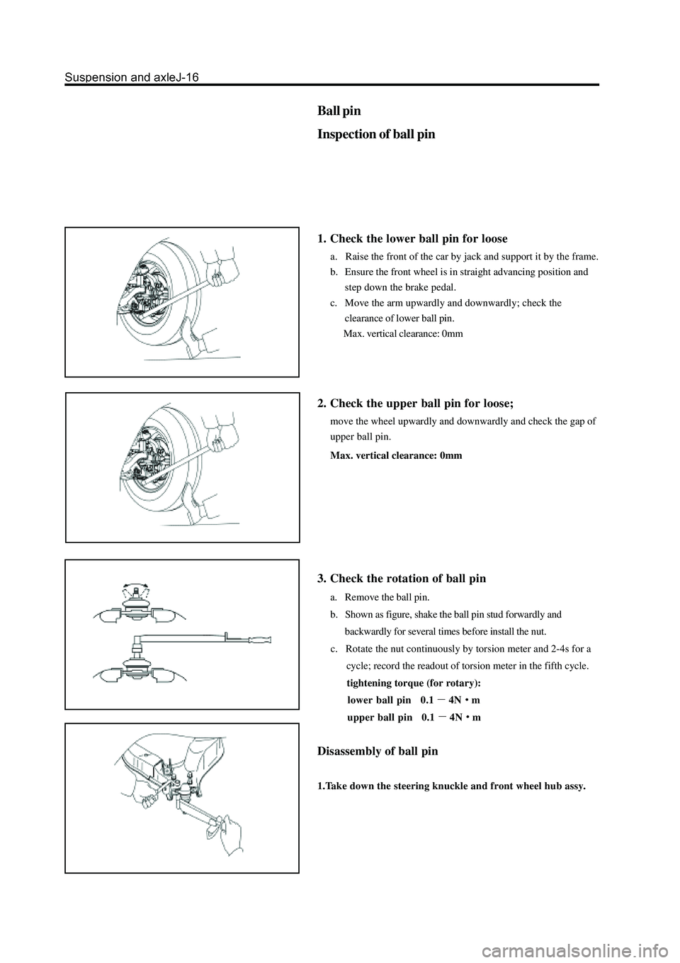
Ball pin
Inspection of ball pin
1. Check the lower ball pin for loose
a. Raise the front of the car by jack and support it by the frame.
b. Ensure the front wheel is in straight advancing position and
step down the brake pedal.
c. Move the arm upwardly and downwardly; check the
clearance of lower ball pin.
Max. vertical clearance: 0mm
2. Check the upper ball pin for loose;
move the wheel upwardly and downwardly and check the gap of
upper ball pin.
Max. vertical clearance: 0mm
3. Check the rotation of ball pin
a. Remove the ball pin.
b. Shown as figure, shake the ball pin stud forwardly and
backwardly for several times before install the nut.
c. Rotate the nut continuously by torsion meter and 2-4s for a
cycle; record the readout of torsion meter in the fifth cycle.
tightening torque (for rotary):
lower ball pin 0.1
4Nm
upper ball pin 0.1
4Nm
Disassembly of ball pin
1.Take down the steering knuckle and front wheel hub assy.
Page 189 of 425
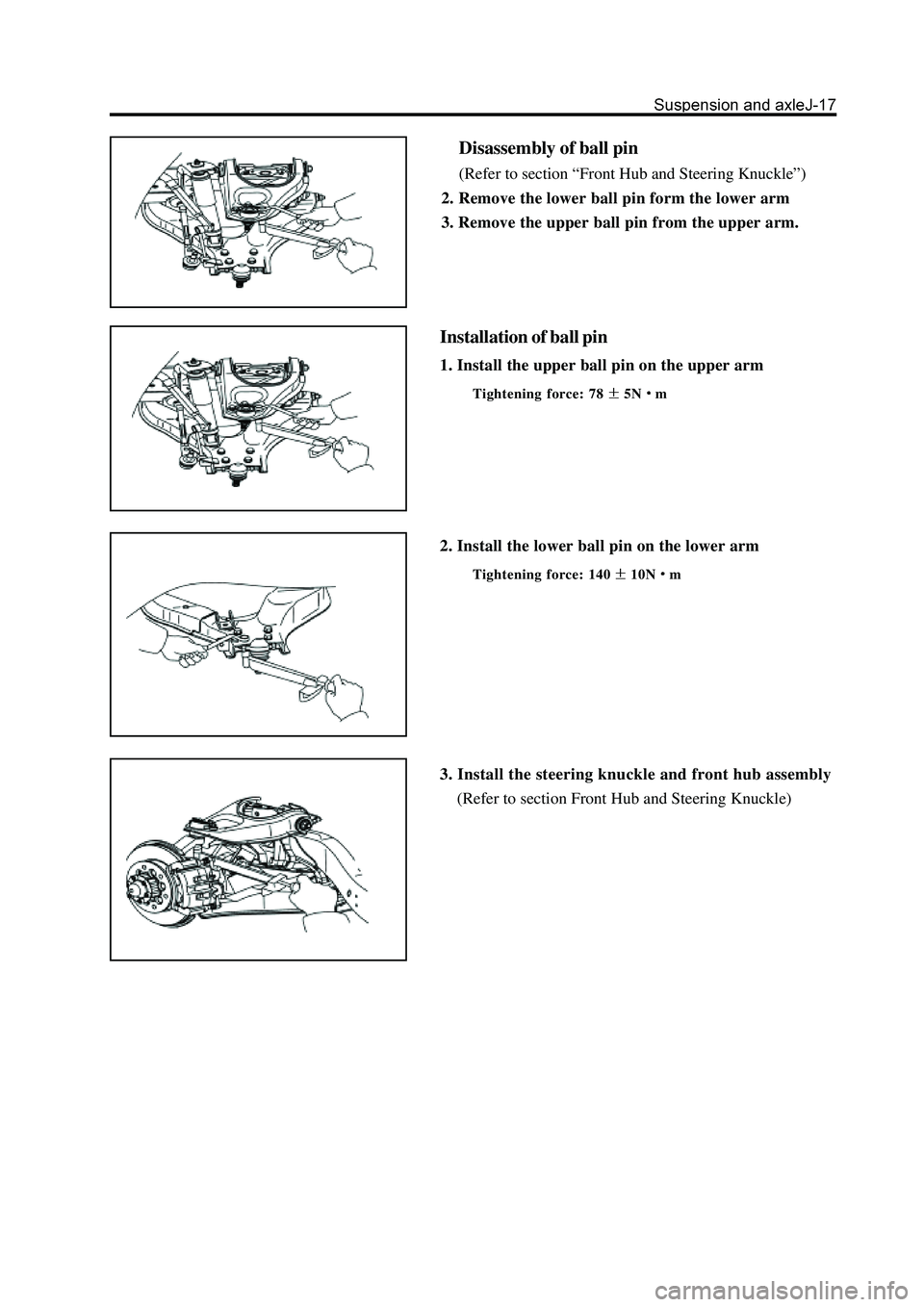
Installation of ball pin
1. Install the upper ball pin on the upper arm
Tightening force: 785Nm
2. Install the lower ball pin on the lower arm
Tightening force: 14010Nm
3. Install the steering knuckle and front hub assembly
(Refer to section Front Hub and Steering Knuckle)
Disassembly of ball pin
(Refer to section “Front Hub and Steering Knuckle”)
2. Remove the lower ball pin form the lower arm
3. Remove the upper ball pin from the upper arm.
Page 190 of 425
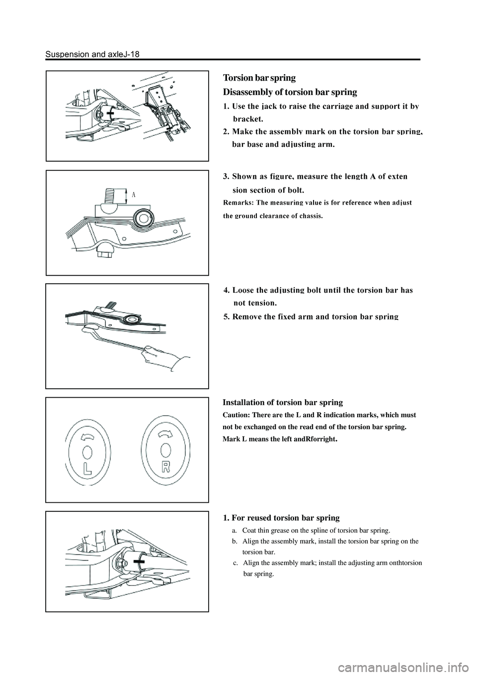
Torsion bar spring
Disassembly of torsion bar spring
Installation of torsion bar spring
Caution: There are the L and R indication marks, which must
not be exchanged on the read end of the torsion bar spring.
Mark L means the left andRforright
.
1. For reused torsion bar spring
a. Coat thin grease on the spline of torsion bar spring.
b. Align the assembly mark, install the torsion bar spring on the
torsion bar.
c. Align the assembly mark; install the adjusting arm onthtorsion
bar spring.