GREAT WALL HOVER 2006 Service Owner's Manual
Manufacturer: GREAT WALL, Model Year: 2006, Model line: HOVER, Model: GREAT WALL HOVER 2006Pages: 425, PDF Size: 26.05 MB
Page 21 of 425
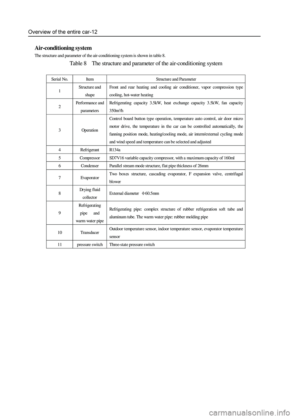
Air-conditioning system
The structure and parameter of the air-conditioning s ystem is shown in table 8.
Table 8 The structure and parameter of the air-conditioning system
Serial No. Item Structure and Paramet er
1 Structure and
shape
Front and rear heating and cooling air conditioner, vapor compression type
cooling, hot-wat er heating
2 Performance and
parameters
Refrigerating capacity 3.5kW, heat exchange capacity 3.5kW, fan capacity
350m
3/h
3 Operation
Control board button type operation, temperature auto control, air door micro
motor drive, the temperature in the car can be controlled automatically, the
fanning position mode, heating/ cooling mode, air int ern/external cycling mode
and wind speed and t emperature can b e selected and adjusted
4 Refrigerant R134a
5 Compressor SD7V16 variable capacity compressor, with a maximum capacity of 160ml
6 Condenser Parallel stream mode structure, flat pipe thickness of 26mm
7 Evaporator Two box es structure, cascading evaporator, F expansion valve, centrifugal
blower
8 Drying fluid
collector
External diameter φ60.5mm
9
Refrigerating
pipe and
wa r m wa t er pi p e
Refrigerating pipe: complex structure of rubber refrigeration soft tube and
aluminum tube. The warm water pipe: rubber molding pipe
10 Transducer Outdoor temp erature sensor, indoor t emperature sensor, evaporator temperature
sensor
11 pressure switch Three-state pressure switch
Page 22 of 425
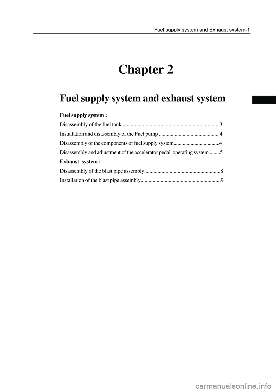
Chapter 2
Fuel supply system and exhaust system
Fuel supply system :
Disassembly of the fuel tank ........................................................................3
Installation and disassembly of the Fuel pump ..............................................4
Disassembly of the components of fuel supply system...................................4
Disassembly and adjustment of the accelerator pedal operating system ........5
Exhaust system :
Disassembly of the blast pipe assembly.........................................................8
Installation of the blast pipe assembly............................................................9
Page 23 of 425
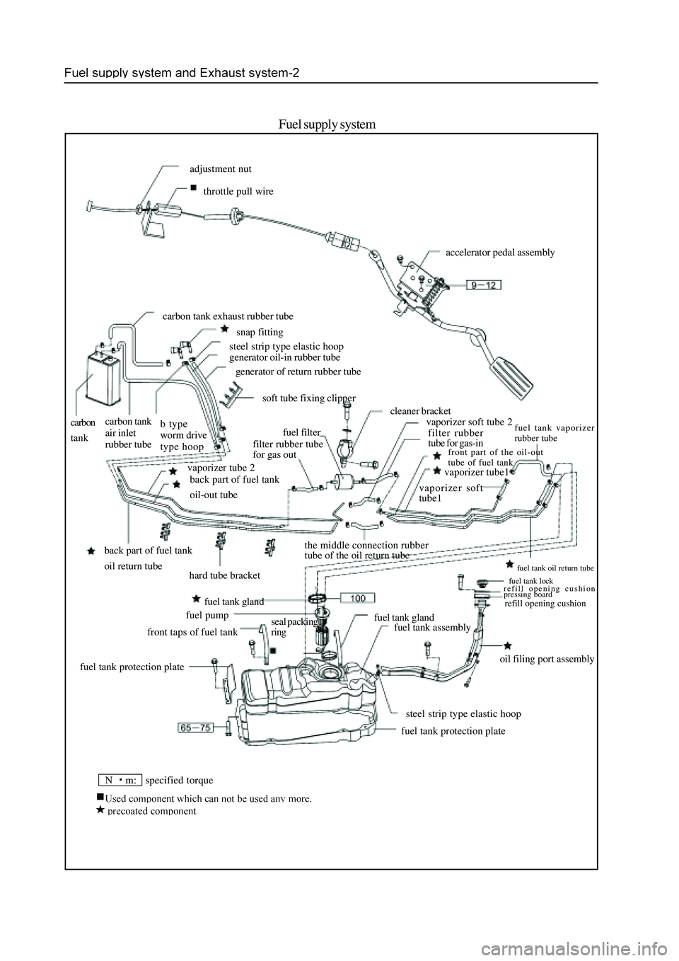
Fuel supply system
N m: specified torque
adjustment nut
throttle pull wire
accelerator pedal assembly
carbon tank exhaust rubber tube
snap fitting
steel strip type elastic hoop
generator oil-in rubber tube
generator of return rubber tube
soft tube fixing clipper
carbon
tankcarbon tank
air inlet
rubber tubeb type
worm drive
type hoop
vaporizer tube 2
back part of fuel tank
oil-out tube
back part of fuel tank
oil return tubefuel filter
filter rubber tube
for gas out
hard tube bracketvaporizer soft tube 2 cleaner bracket
filter rubber
tube for gas-in
fuel tank vaporizer
rubber tube
front part of the oil-out
tube of fuel tank
vaporizer soft
tube1vaporizer tube1
fuel tank gland the middle connection rubber
tube of the oil return tube
front taps of fuel tankfuel pumpfuel tank gland
fuel tank protection plateseal packing
ringfuel tank assembly
fuel tank oil return tube
fuel tank lock
refill opening cushion
pressing board
refill opening cushion
oil filing port assembly
steel strip type elastic hoop
fuel tank protection plate
Page 24 of 425
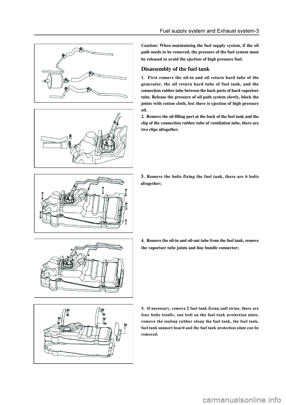
Caution: When maintaining the fuel supply system, if the oil
path needs to be removed, the pressure of the fuel system must
be released to avoid the ejection of high pressure fuel.
Disassembly of the fuel tank
1. First remove the oil-in and oil return hard tube of the
generator, the oil return hard tube of fuel tank, and the
connection rubber tube between the back parts of hard vaporizer
tube. Release the pressure of oil path system slowly, block the
joints with cotton cloth, lest there is ejection of high pressure
oil.
2. Remove the oil filling port at the back of the fuel tank and the
clip of the connection rubber tube of ventilation tube, there are
two clips altogether.
3. Remove the bolts fixing the fuel tank, there are 6 bolts
altogether;
4. Remove the oil-in and oil-out tube from the fuel tank, remove
the vaporizer tube joints and line bundle connector;
Page 25 of 425
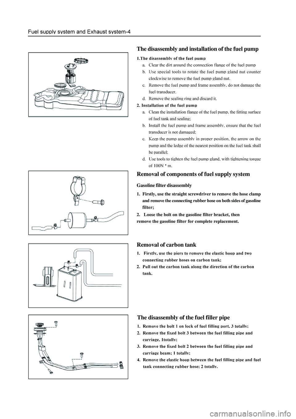
The disassembly and installation of the fuel pump
Removal of components of fuel supply system
Gasoline filter disassembly
1. Firstly, use the straight screwdriver to remove the hose clamp
and remove the connecting rubber hose on both sides of gasoline
filter;
2. Loose the bolt on the gasoline filter bracket, then
remove the gasoline filter for complete replacement.
Removal of carbon tank
The disassembly of the fuel filler pipe
Page 26 of 425
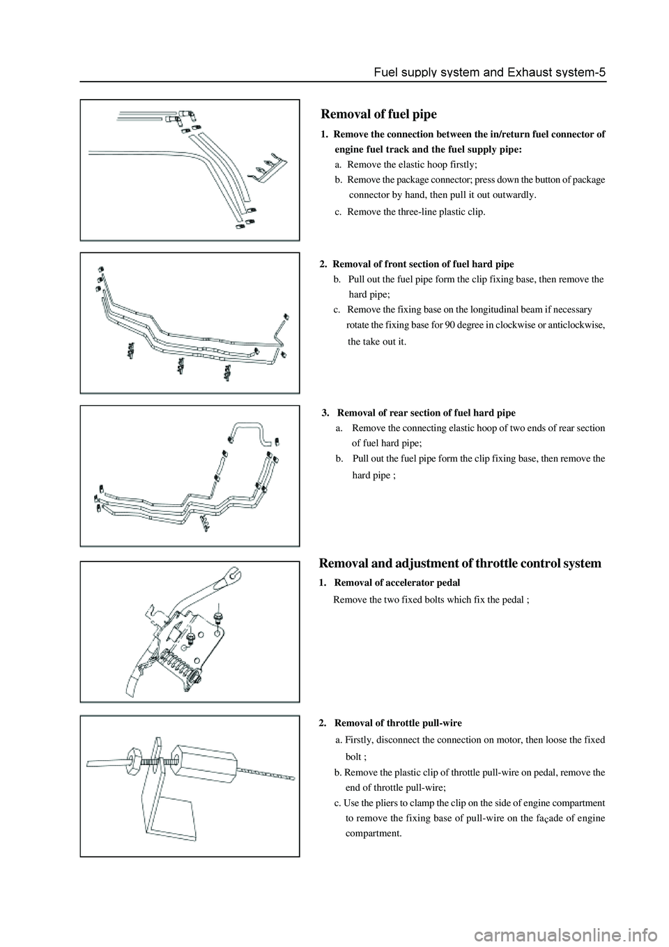
Removal of fuel pipe
1. Remove the connection between the in/return fuel connector of
engine fuel track and the fuel supply pipe:
a. Remove the elastic hoop firstly;
b. Remove the package connector; press down the button of package
connector by hand, then pull it out outwardly.
c. Remove the three-line plastic clip.
2. Removal of front section of fuel hard pipe
b. Pull out the fuel pipe form the clip fixing base, then remove the
hard pipe;
c. Remove the fixing base on the longitudinal beam if necessary
rotate the fixing base for 90 degree in clockwise or anticlockwise,
the take out it.
3. Removal of rear section of fuel hard pipe
a. Remove the connecting elastic hoop of two ends of rear section
of fuel hard pipe;
b. Pull out the fuel pipe form the clip fixing base, then remove the
hard pipe ;
Removal and adjustment of throttle control system
1. Removal of accelerator pedal
Remove the two fixed bolts which fix the pedal ;
2. Removal of throttle pull-wire
a. Firstly, disconnect the connection on motor, then loose the fixed
bolt ;
b. Remove the plastic clip of throttle pull-wire on pedal, remove the
end of throttle pull-wire;
c. Use the pliers to clamp the clip on the side of engine compartment
to remove the fixing base of pull-wire on the fa
ade of engine
compartment.
Page 27 of 425
Page 28 of 425
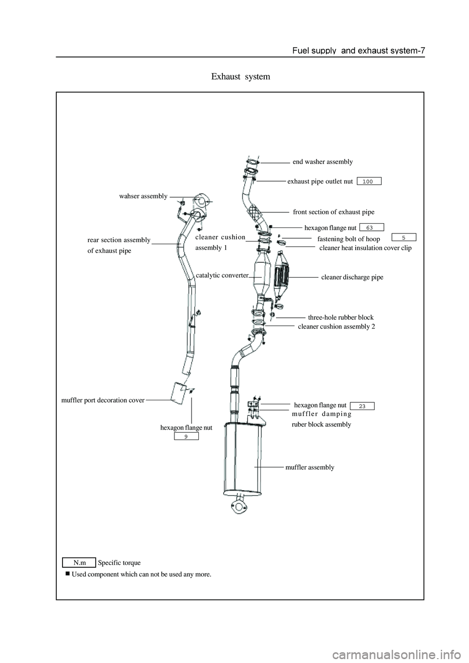
Exhaust system
N.m Specific torque
Used component which can not be used any more.
end washer assembly
exhaust pipe outlet nut
front section of exhaust pipe
hexagon flange nut
cleaner cushion
assembly 1
fastening bolt of hoop
cleaner heat insulation cover clip
cleaner discharge pipe catalytic converter
three-hole rubber block
cleaner cushion assembly 2
hexagon flange nut
muffler assembly
muffler port decoration cover
hexagon flange nut
rear section assembly
of exhaust pipe
wahser assembly
100
9
63
5
23muffler damping
ruber block assembly
Page 29 of 425
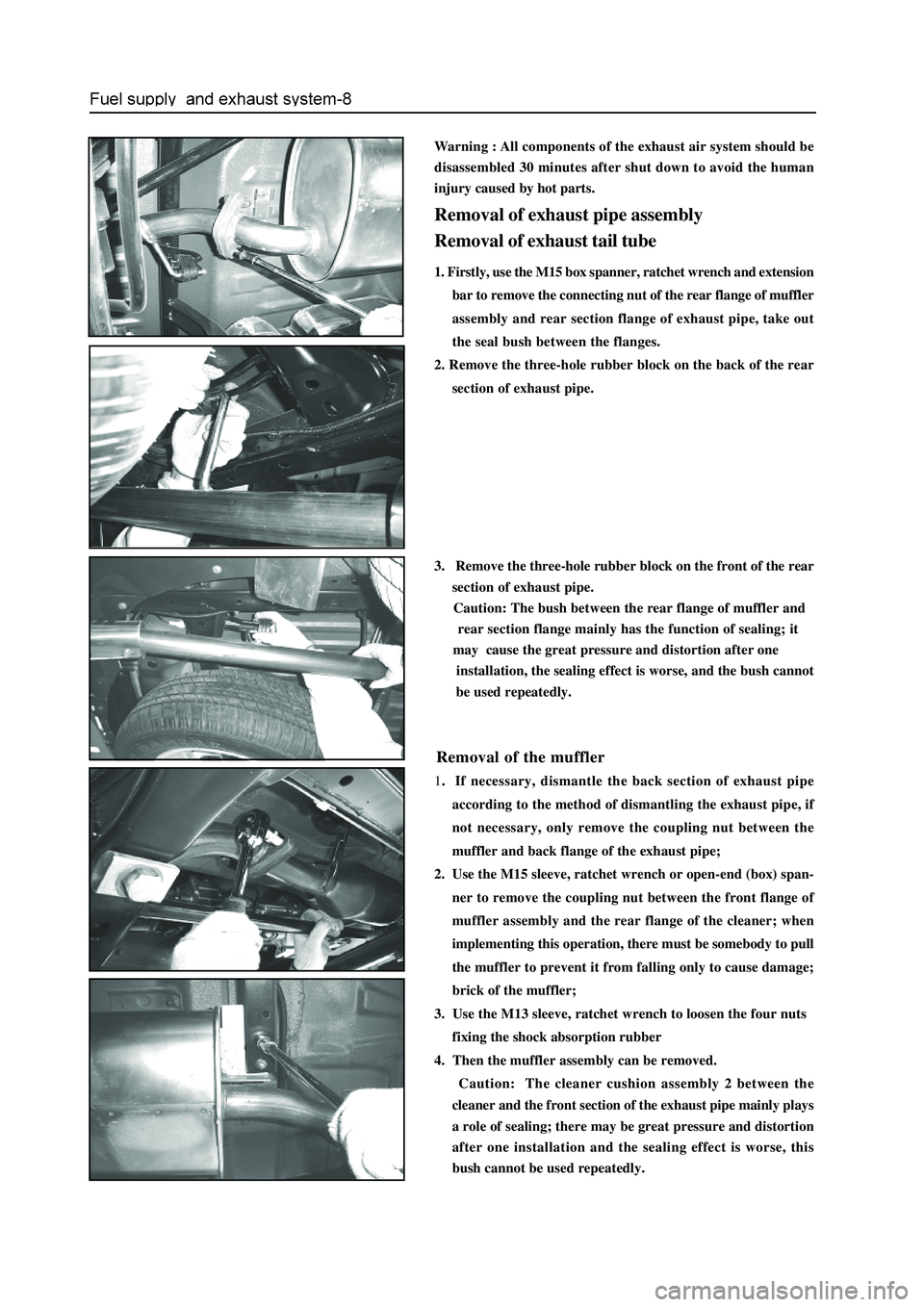
Warning : All components of the exhaust air system should be
disassembled 30 minutes after shut down to avoid the human
injury caused by hot parts.
Removal of exhaust pipe assembly
Removal of exhaust tail tube
1. Firstly, use the M15 box spanner, ratchet wrench and extension
bar to remove the connecting nut of the rear flange of muffler
assembly and rear section flange of exhaust pipe, take out
the seal bush between the flanges.
2. Remove the three-hole rubber block on the back of the rear
section of exhaust pipe.
3. Remove the three-hole rubber block on the front of the rear
section of exhaust pipe.
Caution: The bush between the rear flange of muffler and
rear section flange mainly has the function of sealing; it
may cause the great pressure and distortion after one
installation, the sealing effect is worse, and the bush cannot
be used repeatedly.
Removal of the muffler
1. If necessary, dismantle the back section of exhaust pipe
according to the method of dismantling the exhaust pipe, if
not necessary, only remove the coupling nut between the
muffler and back flange of the exhaust pipe;
2. Use the M15 sleeve, ratchet wrench or open-end (box) span-
ner to remove the coupling nut between the front flange of
muffler assembly and the rear flange of the cleaner; when
implementing this operation, there must be somebody to pull
the muffler to prevent it from falling only to cause damage;
brick of the muffler;
3. Use the M13 sleeve, ratchet wrench to loosen the four nuts
fixing the shock absorption rubber
4. Then the muffler assembly can be removed.
Caution: The cleaner cushion assembly 2 between the
cleaner and the front section of the exhaust pipe mainly plays
a role of sealing; there may be great pressure and distortion
after one installation and the sealing effect is worse, this
bush cannot be used repeatedly.
Page 30 of 425
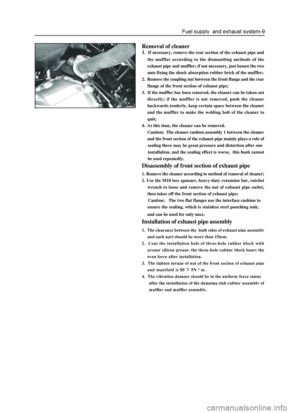
Removal of cleaner
1. If necessary, remove the rear section of the exhaust pipe and
the muffler according to the dismantling methods of the
exhaust pipe and muffler; if not necessary, just loosen the two
nuts fixing the shock absorption rubber brick of the muffler;
2. Remove the coupling nut between the front flange and the rear
flange of the front section of exhaust pipe;
3. If the muffler has been removed, the cleaner can be taken out
directly; if the muffler is not removed, push the cleaner
backwards tenderly, keep certain space between the cleaner
and the muffler to make the welding bolt of the cleaner to
quit;
4. At this time, the cleaner can be removed.
Caution: The cleaner cushion assembly 1 between the cleaner
and the front section of the exhaust pipe mainly plays a role of
sealing there may be great pressure and distortion after one
installation, and the sealing effect is worse, this bush cannot
be used repeatedly.
Disassembly of front section of exhaust pipe
1. Remove the cleaner according to method of removal of cleaner;
2. Use the M18 box spanner, heavy-duty extension bar, ratchet
wrench to loose and remove the nut of exhaust pipe outlet,
then takes off the front section of exhaust pipe;
Caution: The two flat flanges use the interface cushion to
ensure the sealing, which is stainless steel punching unit,
and can be used for only once.
Installation of exhaust pipe assembly