transmission fluid GREAT WALL HOVER 2006 Service Repair Manual
[x] Cancel search | Manufacturer: GREAT WALL, Model Year: 2006, Model line: HOVER, Model: GREAT WALL HOVER 2006Pages: 425, PDF Size: 26.05 MB
Page 78 of 425
Automatic transmission-2
Instruction for automatic transmission
1. M88 4-speed automatic transmission is equipped with the hydraulic torque converter and electric control system with locking.
When keep the stable forward status, the hydraulic torque converter can be locked automatically when the engine operates in low
speed, then reduce the unnecessary slide.
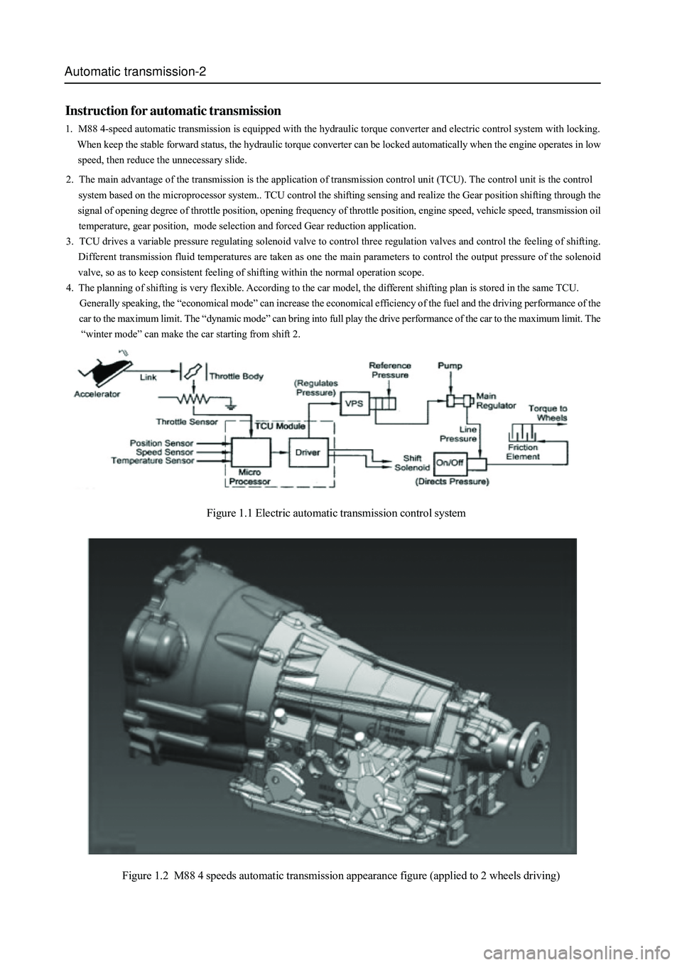
Figure 1.1 Electric automatic transmission control system
Figure 1.2 M88 4 speeds automatic transmission appearance figure (applied to 2 wheels driving)
2. The main advantage of the transmission is the application of transmission control unit (TCU). The control unit is the control
system based on the microprocessor system.. TCU control the shifting sensing and realize the Gear position shifting through the
signal of opening degree of throttle position, opening frequency of throttle position, engine speed, vehicle speed, transmission oil
temperature, gear position, mode selection and forced Gear reduction application.
3. TCU drives a variable pressure regulating solenoid valve to control three regulation valves and control the feeling of shifting.
Different transmission fluid temperatures are taken as one the main parameters to control the output pressure of the solenoid
valve, so as to keep consistent feeling of shifting within the normal operation scope.
4. The planning of shifting is very flexible. According to the car model, the different shifting plan is stored in the same TCU.
Generally speaking, the “economical mode” can increase the economical efficiency of the fuel and the driving performance of the
car to the maximum limit. The “dynamic mode” can bring into full play the drive performance of the car to the maximum limit. The
“winter mode” can make the car starting from shift 2.
Page 83 of 425
Automatic transmission-7
Indicator lamp
Figure 2.2
control system
General
The transmission has two sets of control system, a electric control system and a hydraulic control system. The electric control
system monitors the vehicle parameter and adjusts the transmission performance; the hydraulic control system executes the
command of electric control system.
Electric control system
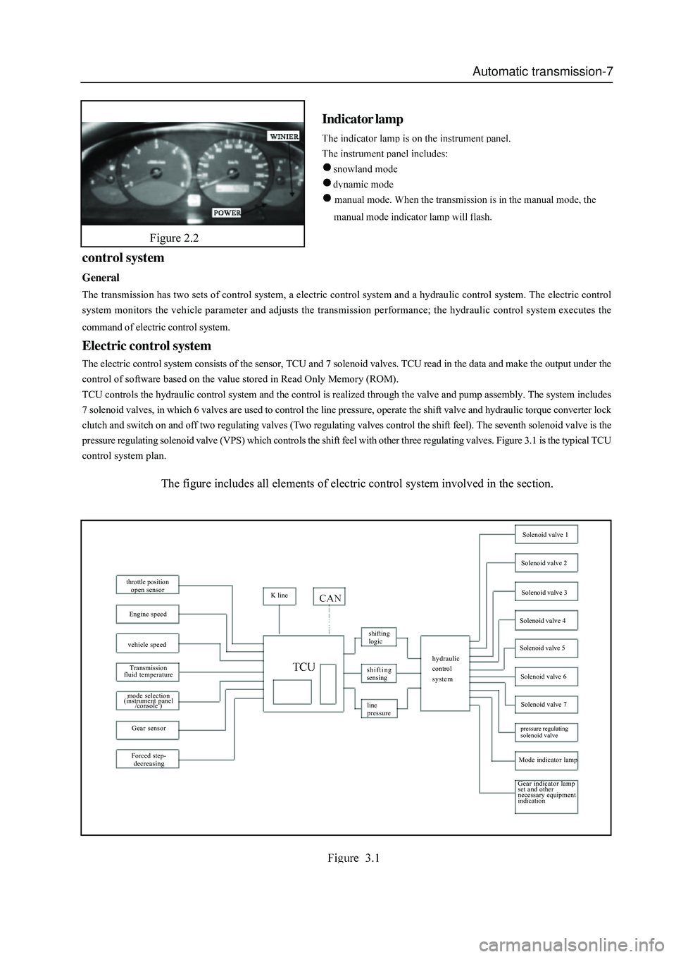
The electric control system consists of the sensor, TCU and 7 solenoid valves. TCU read in the data and make the output under the
control of software based on the value stored in Read Only Memory (ROM).
TCU controls the hydraulic control system and the control is realized through the valve and pump assembly. The system includes
7 solenoid valves, in which 6 valves are used to control the line pressure, operate the shift valve and hydraulic torque converter lock
clutch and switch on and off two regulating valves (Two regulating valves control the shift feel). The seventh solenoid valve is the
pressure regulating solenoid valve (VPS) which controls the shift feel with other three regulating valves. Figure 3.1 is the typical TCU
control system plan.
The figure includes all elements of electric control system involved in the section.
throttle position
open sensor
Engine speed
vehicle speed
Transmission
fluid temperature
mode selection
(instrument panel
/console )
Gear sensor
Forced step-
decreasingK line
shifting
logic
shifting
sensing
line
pressurehydraulic
control
system
Solenoid valve 1
Solenoid valve 2
Solenoid valve 3
Solenoid valve 4
Solenoid valve 5
Solenoid valve 6
Solenoid valve 7
pressure regulating
solenoid valve
Mode indicator lamp
Gear indicator lamp
set and other
necessary equipment
indication
Page 90 of 425
Automatic transmission-14
The main box includes:
�z BIR blow-off valve
1. Valve
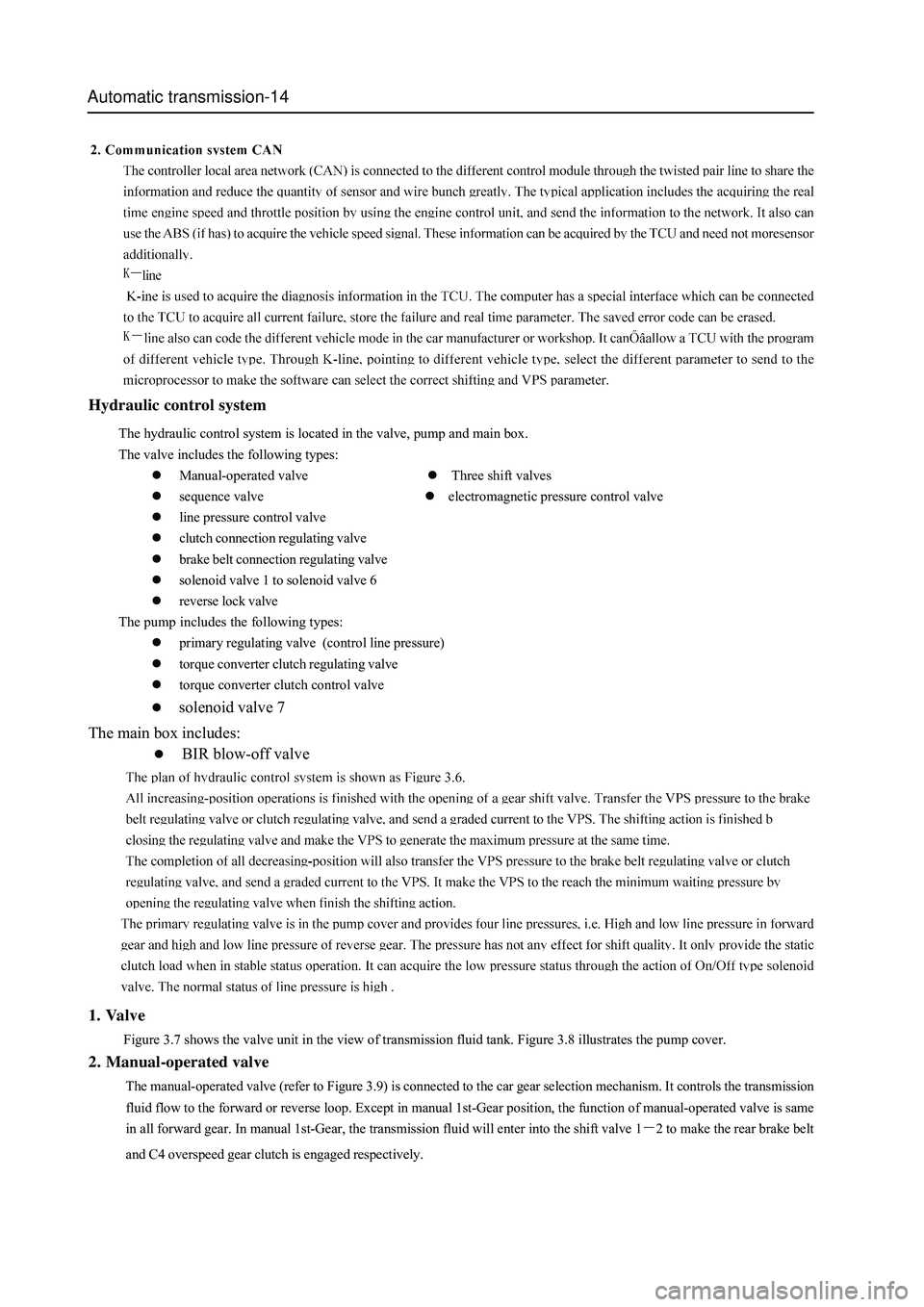
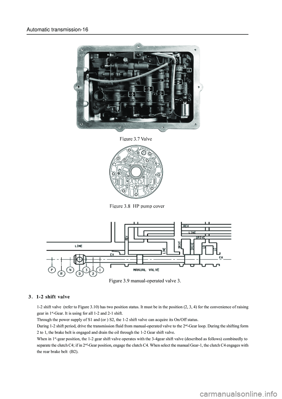
Figure 3.7 shows the valve unit in the view of transmission fluid tank. Figure 3.8 illustrates the pump cover.
2. Manual-operated valve
The manual-operated valve (refer to Figure 3.9) is connected to the car gear selection mechanism. It controls the transmission
fluid flow to the forward or reverse loop. Except in manual 1st-Gear position, the function of manual-operated valve is same
in all forward gear. In manual 1st-Gear, the transmission fluid will enter into the shift valve 1
2 to make the rear brake belt
and C4 overspeed gear clutch is engaged respectively. The hydraulic control system is located in the valve, pump and main box.
The valve includes the following types:
�zManual-operated valve
�z Three shift valves
�zsequence valve
�z electromagnetic pressure control valve
�zline pressure control valve
�zclutch connection regulating valve
�zbrake belt connection regulating valve
�zsolenoid valve 1 to solenoid valve 6
�zreverse lock valve
The pump includes the following types:
�zprimary regulating valve (control line pressure)
�ztorque converter clutch regulating valve
�ztorque converter clutch control valve
�z
solenoid valve 7 Hydraulic control system
Page 92 of 425
Automatic transmission-16
Figure 3.9 manual-operated valve 3.
1-2 shift valve (refer to Figure 3.10) has two position status. It must be in the position (2, 3, 4) for the convenience of raising
gear in 1
st-Gear. It is using for all 1-2 and 2-1 shift.
Through the power supply of S1 and (or ) S2, the 1-2 shift valve can acquire its On/Off status.
During 1-2 shift period, drive the transmission fluid from manual-operated valve to the 2
nd-Gear loop. During the shifting form
2 to 1, the brake belt is engaged and drain the oil through the 1-2 Gear shift valve.
When in 1
st-gear position, the 1-2 gear shift valve operates with the 3-4gear shift valve (described as follows) combinedly to
separate the clutch C4; if in 2
nd-Gear position, engage the clutch C4. When select the manual Gear-1, the clutch C4 engages with
the rear brake belt (B2).
31-2 shift valve
Page 95 of 425
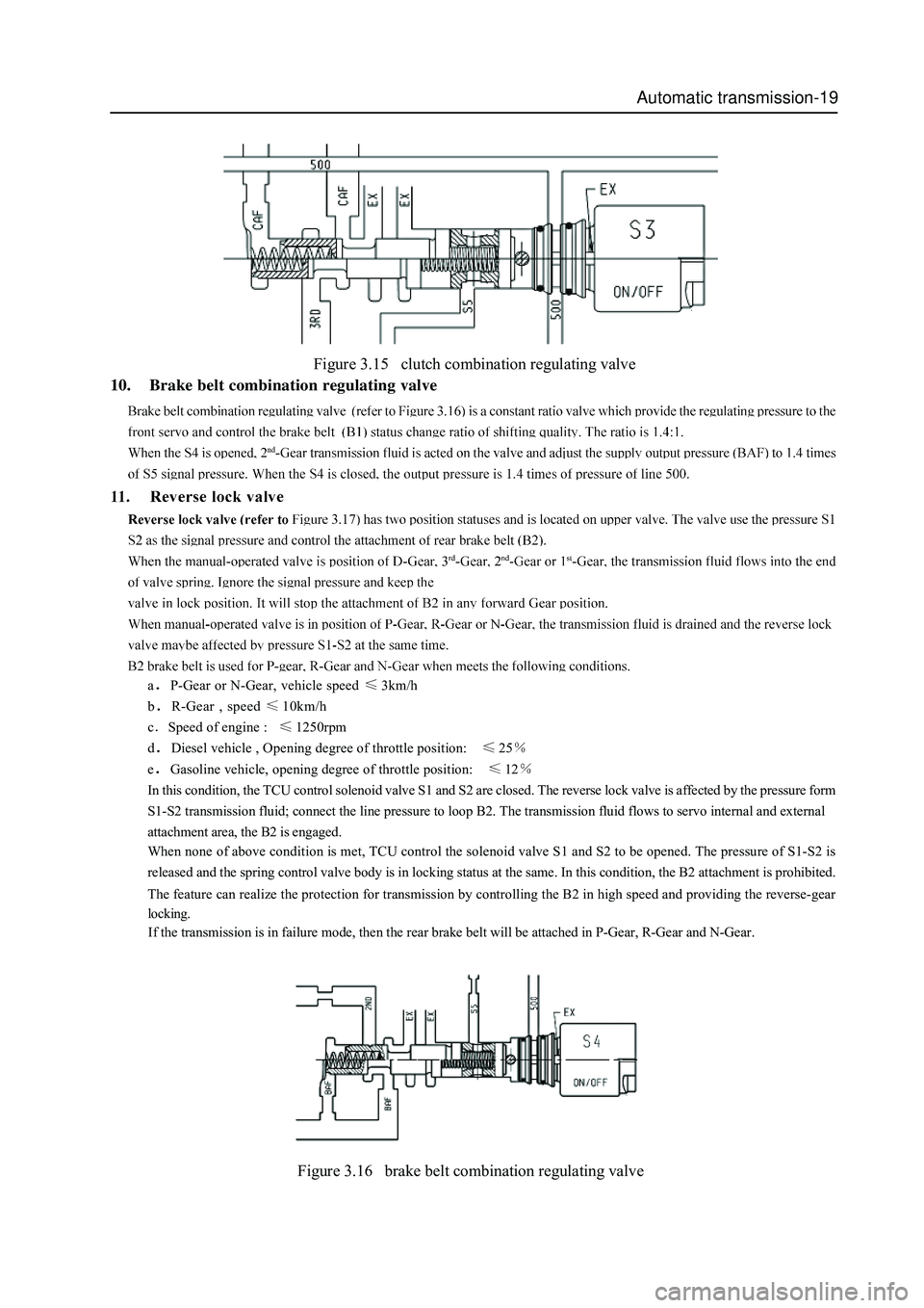
Automatic transmission-19
Figure 3.15 clutch combination regulating valve
10. Brake belt combination regulating valve
aP-Gear or N-Gear, vehicle speed 3km/h
b
R-Gear , speed 10km/h
c
Speed of engine : 1250rpm
d
Diesel vehicle , Opening degree of throttle position: 25
eGasoline vehicle, opening degree of throttle position: 12
In this condition, the TCU control solenoid valve S1 and S2 are closed. The reverse lock valve is affected by the pressure form
S1-S2 transmission fluid; connect the line pressure to loop B2. The transmission fluid flows to servo internal and external
attachment area, the B2 is engaged.
When none of above condition is met, TCU control the solenoid valve S1 and S2 to be opened. The pressure of S1-S2 is
released and the spring control valve body is in locking status at the same. In this condition, the B2 attachment is prohibited.
The feature can realize the protection for transmission by controlling the B2 in high speed and providing the reverse-gear
locking.
If the transmission is in failure mode, then the rear brake belt will be attached in P-Gear, R-Gear and N-Gear.
Figure 3.16 brake belt combination regulating valve
Page 98 of 425
Automatic transmission-22
Power transmission system
The power transmission system includes:
Torque converter equipped with single lock clutch.
4 multi-plate clutch assemblies
2 brake belts
2 one-way clutches
Planetary gear assembly
parking mechanism
A traditional planetary gear assembly composed by six pinions is used in four-speed transmission. It realizes the 4 Gear power
transmission through the drive gear bracket.
So, the cross arrangement is the main arranging method. In the box, there are four subassemblies, shown as follows:
Gear bank central support
C1-C2-C3-clutch C4 subassembly
Pump assembly
Valve assembly
One piece or one set of optional shim is located between the input shaft flange and center of stator support shaft axle of and used
to control the end flotation of transmission. The structure arrangement allows the inspection for the subassembly during the
product manufacturing period.
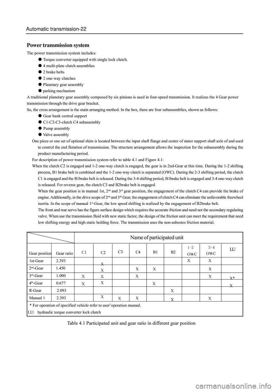
For description of power transmission system refer to table 4.1 and Figure 4.1:
When the clutch C2 is engaged and 1-2 one-way clutch is engaged, the gear is in 2nd-Gear at this time. During the 1-2 shifting
process, B1 brake belt is combined and the 1-2 one-way clutch is separated (OWC). During the 2-3 shifting period, the clutch
C1 is engaged and the B1brake belt is released. During the 3-4 shifting period, B1brake belt is engaged and 3-4 one-way clutch
is released. For reverse gear, the clutch C3 and B2brake belt is engaged.
When the gear position is in manual 1st, 2
nd and 3rd gear position, the engagement of the clutch C4 can provide the brake of
engine. Additionally, in the drive scope of 2
nd and 3rd Gear, the engagement of clutch C4 can eliminate the unfavorable freewheel
inertia. In the scope of manual 1
st-Gear, the low speed shifting is realized by the engagement of B2brake belt.
The front and rear servo has the figure surface design which requires the accurate friction and need not the secondary regulating
valve. When use the transmission fluid with new static factor, the design of the friction unit can meet the requirement that need
low shifting energy and high static holding force. The transmission uses the non-asbestos friction material.
LUGear position Gear ratio
1st-Gear 2.393
2
nd-Gear 1.450
3
rd-Gear 1.000
4
th-Gear 0.677
R-Gear 2.093
Manual 1 2.393
C3C4 B1 B2
Name of participated unit
* For operation of specified vehicle refer to user’operation manual.
LU: hydraulic torque converter lock clutch
Table 4.1 Participated unit and gear ratio in different gear position
Page 102 of 425
Automatic transmission-26
Power transmission
Introduction
It has the following power transmission pointed to different Gear-position:
power transmission N-Gear and P-Gear
power transmission R-Gear
power transmission manual 1
power transmission Automatic 1st-Gear
power transmission Automatic 2nd -Gear
power transmission Automatic 3rd -Gear
power transmission Automatic 3rd-Gear locking
power transmission Automatic 4th -Gear (overspeed -gear)
power transmission Automatic 4th -Gear locking
For description of each kind of power transmission condition, refer to following parts.
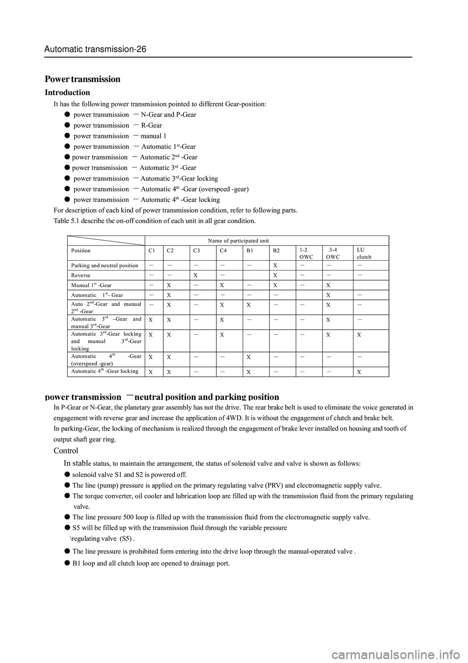
Table 5.1 describe the on-off condition of each unit in all gear condition.
Name of participated unit
Position C1 C2 C3 C4 B1 B2 1-2
OWC 3-4
OWC LU
clutch
Parking and neutral position - - - - - X - - -
Reverse - - X - X - - -
Manual 1st -G ear - X - X - X - X
Automatic 1st- Gear - X - - - - X -
Auto 2nd-Gear and manual
2nd -G ear - X - X X - - X - Automatic 3rd –Gear and
manual 3rd-Gear X X - X - - - X - Automatic 3rd-Gear locking
and manual 3rd-Gear
locking X X - X - - - X X
Automatic 4th -Gear
(overspeed -gear) X X - - X - - - -
Automatic 4th -Gear locking
X X - - X - - - X
In P-Gear or N-Gear, the planetary gear assembly has not the drive. The rear brake belt is used to eliminate the voice generated in
engagement with reverse gear and increase the application of 4WD. It is without the engagement of clutch and brake belt.
In parking-Gear, the locking of mechanism is realized through the engagement of brake lever installed on housing and tooth of
output shaft gear ring.
Control
In stabl
e status, to maintain the arrangement, the status of solenoid valve and valve is shown as follows:
solenoid valve S1 and S2 is powered off.
The line (pump) pressure is applied on the primary regulating valve (PRV) and electromagnetic supply valve.
The torque converter, oil cooler and lubrication loop are filled up with the transmission fluid from the primary regulating
valve.
The line pressure 500 loop is filled up with the transmission fluid from the electromagnetic supply valve.
S5 will be filled up with the transmission fluid through the variable pressure
egulating valve (S5) .
The line pressure is prohibited form entering into the drive loop through the manual-operated valve .
B1 loop and all clutch loop are opened to drainage port.
Page 107 of 425
Automatic transmission-31
Power transmission manual 1st-Gear
In manual 1st –Gear, the drive of transmission is send to the rear clutch cylinder through the input shaft. In this
condition, each function unit of transmission is shown as follows:
The clutch C2 is engaged through the 3-4 one-way clutch (OWC) to drive the front sun gear.
The engagement of B2 brake belt make the planetary gear carrier to stop.
The front sun gear drive the short planetary gear to rotate in anticlockwise.
The short planetary gear drive the long planetary gear to rotate in clockwise.
The long planetary gear rotate around its axial to drive the internal gear ring and output
shaft to rotate in clockwise to realize the movement in forward direction.
In overspeed, clutch C4 can provides certain brake force through 3-4 one-way clutch .
Control:
In stable status, the action of solenoid valve and valve is shown as follows:
The solenoid valve S1 and S2 is powered on.
In the action of pressure of line 500, the gear shift valve of 1-2, 2-3, 3-4 gear are kept in position of 1st-Gear.
The manual-operated valve transmission fluid (line pressure ) makes the clutch C2 to engagement.
LO-1st (line pressure) oil flows to the clutch C4 through the 1-2 Gear switching valve to engage the B2 brake belt.
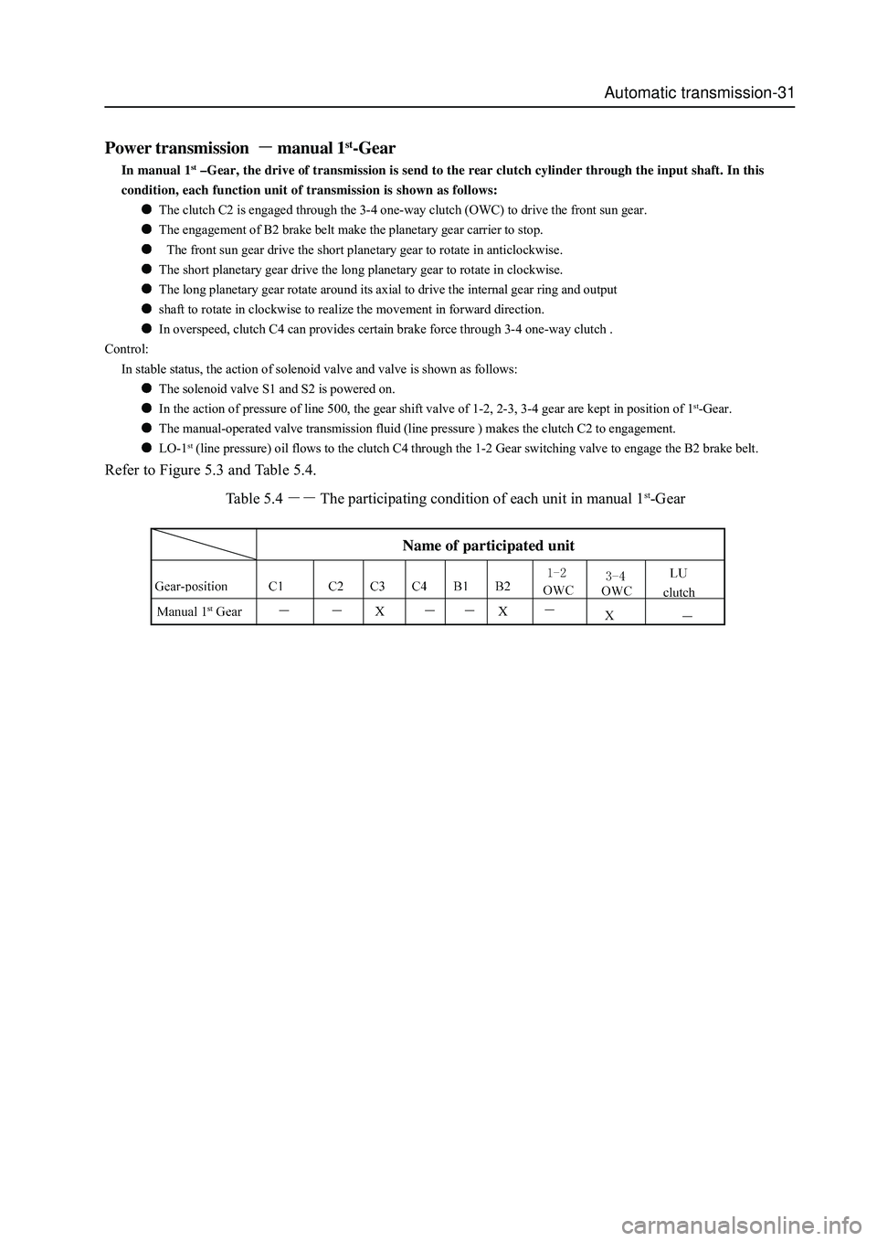
Refer to Figure 5.3 and Table 5.4.
Table 5.4
The participating condition of each unit in manual 1st-Gear
Name of participated unit
X X
Page 113 of 425
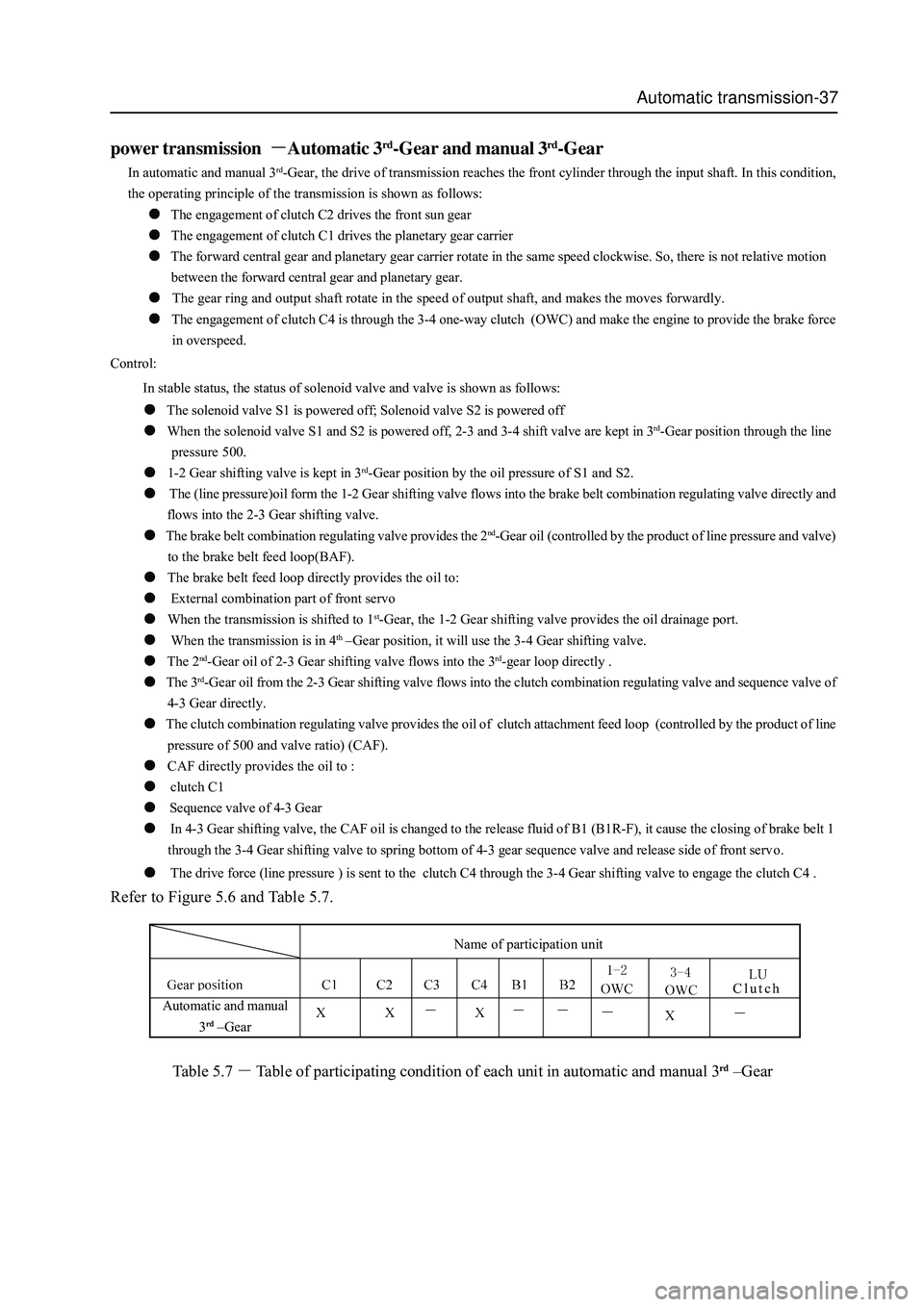
Automatic transmission-37
power transmission Automatic 3rd-Gear and manual 3rd-Gear
In automatic and manual 3rd-Gear, the drive of transmission reaches the front cylinder through the input shaft. In this condition,
the operating principle of the transmission is shown as follows:
The engagement of clutch C2 drives the front sun gear
The engagement of clutch C1 drives the planetary gear carrier
The forward central gear and planetary gear carrier rotate in the same speed clockwise. So, there is not relative motion
between the forward central gear and planetary gear.
The gear ring and output shaft rotate in the speed of output shaft, and makes the moves forwardly.
The engagement of clutch C4 is through the 3-4 one-way clutch (OWC) and make the engine to provide the brake force
in overspeed.
Control:
In stable status, the status of solenoid valve and valve is shown as follows:
The solenoid valve S1 is powered off; Solenoid valve S2 is powered off
When the solenoid valve S1 and S2 is powered off, 2-3 and 3-4 shift valve are kept in 3rd-Gear position through the line
pressure 500.
1-2 Gear shifting valve is kept in 3rd-Gear position by the oil pressure of S1 and S2.
The (line pressure)oil form the 1-2 Gear shifting valve flows into the brake belt combination regulating valve directly and
flows into the 2-3 Gear shifting valve.
The brake belt combination regulating valve provides the 2nd-Gear oil (controlled by the product of line pressure and valve)
to the brake belt feed loop(BAF).
The brake belt feed loop directly provides the oil to:
External combination part of front servo
When the transmission is shifted to 1st-Gear, the 1-2 Gear shifting valve provides the oil drainage port.
When the transmission is in 4th –Gear position, it will use the 3-4 Gear shifting valve.
The 2nd-Gear oil of 2-3 Gear shifting valve flows into the 3rd-gear loop directly .
The 3rd-Gear oil from the 2-3 Gear shifting valve flows into the clutch combination regulating valve and sequence valve of
4-3 Gear directly.
The clutch combination regulating valve provides the oil of clutch attachment feed loop (controlled by the product of line
pressure of 500 and valve ratio) (CAF).
CAF directly provides the oil to :
clutch C1
Sequence valve of 4-3 Gear
In 4-3 Gear shifting valve, the CAF oil is changed to the release fluid of B1 (B1R-F), it cause the closing of brake belt 1
through the 3-4 Gear shifting valve to spring bottom of 4-3 gear sequence valve and release side of front servo.
The drive force (line pressure ) is sent to the clutch C4 through the 3-4 Gear shifting valve to engage the clutch C4 .
Refer to Figure 5.6 and Table 5.7.
Table 5.7
Table of participating condition of each unit in automatic and manual 3rd –Gear
Clutch
Name of participation unit
Automatic and manual
3
rd –Gear
Page 121 of 425

Automatic transmission-45
Diagnosis and test
Test system
1. Recommended test equipment and program
The test equipment and control unit for design will be used for the test of all vehicles. The parts for transmission test includes:
Tester for service after sales
Special vehicle for test
2. Tester for service after sales
After the special programming, the tester equipped with special car test software can be used to test the specified system and unit.
The program allows the normal communication between the transmission control units (TCUs) .
The computer needs the required information from the customer and select the necessary data through the manual. For example:
view the code, clear the error code and make the real-time operation. For detailed operating instruction refer to user’s manual.
The equipment can be used by the trained specialized persons, such as technician, machinist to test the electronic and loop
problem related to transmission. The testable information includes: the engine speed, rode (shaft speed), transmission fluid
temperature, position of throttle position, status of solenoid valve and gear and position of operating lever. Additionally, it can be
used to detect the current and stored problem.
3. Description of TCU pin
The description of TCU pin code had been listed in Table 6.1.1
For description of wire bunch refer to Figure 6.1.1
Pin No. Function Type 2WD description
A14 Public grounding GND
● Negative pole of TCU supply, connected to negative pole of
battery.
A13 Nonuse
--
○ -----
A12 M ode indicator la mp
Snowland mode OP
● Indicate that select the “Snowland M ode” operating method.
A11 Parking-Gear indicator lamp O P
● T he drive instrum ent panel indicator la mp indicates tha t is in
the “Parking G ear”
A10 Reverse-Gear indicator lamp OP
● T he drive instrum ent panel indicator la mp indicates tha t is in
“ Revers e G ear”
A9 N-G ear indicator lamp O P
● T he drive instrum ent panel indicator la mp indicates tha t is in
“Idle N Gear”
A8 Nonuse -- ○ -----
A7 Nonuse -- ○ -----
A6 M ode indicator la mp
dynamic mode OP
● Indicate that select the “ dyna m ic mode” operating method.
A5 Nonuse ―― ○ ---――
A4 Nonuse ―― ○ -----
A3 Nonuse ―― ○ -----
A2 Mode switch IP
● The switch is used to select the “economic mode”, “dynamic
m ode” and “ snowla nd mode”. T he voltage is varia ble in
range of 0 V-2V .
A1 Nonuse ―― ○ -----
A30 Power supply PWR
● Power supply for TCU; is the main power source of drive
unit and solenoid valve.
A29 Nonuse ―― ○ -----
A28 1st-G ear indicator lamp
/1st-G ear position﹡ OP
● Drive the instrument panel indicator lamp indication, indicate
that the gear-position is in “1st-G ear”
A27 2nd-G ear indicator lamp
/2nd-G ear position OP
● Drive the instrument panel indicator lamp indication, indicate
that the gear-position is in “2nd-G ear”
A26 3rd-G ear indicator lamp
/3rd-Gear position﹡ OP
● Drive the instrument panel indicator lamp indication, indicate
that the gear-position is in “3rd-Gear”
A25 Automatic gear indicator
lamp /4th –Gear position OP
● Drive the instrument panel indicator lamp indication, indicate
that the gear-position is in “automatic-Gear”